
Multiband printed monopole and dipole antenna with square-nested fractal
2012-08-13 09:16WANGLinaLINShuCAIRunnanHUANGGuanlongZHANGWenbin
WANG Li-na,LIN Shu,2,CAI Run-nan,HUANG Guan-long,ZHANG Wen-bin
王丽娜, 林 澍, 蔡闰南, 黄冠龙, 张文彬
(1.School of Electronics and Information Engineering,Harbin Institute of Technology,Harbin 150080,China;2.Electronic Science and Technology Post-doctoral Research Center,Harbin Institute of Technology,Harbin 150080,China)
With the development of wireless communication technology,all the channel capacity’s expansion,the transmission rate’s improvement and the mutual-compatibility among different operation systems,as well as the flexibility of service patterns,make operating band of wireless communication grow faster.Multiband antennas are required in mutual communication between different systems,including GSM900/1800,CDMA,GPRS,2.4 GHz Bluetooth communication and 3.5 GHz WiMAX systems.Due to the miniaturization and integration are much considered in devices’design,so that researchers focus urgently on antennas’miniaturization,multiband and integration.
Recent researches have presented that the design methods,which are used to realize antenna’s multiband characteristic,mainly contain resonantelements[1-3], multiple modes[4], slots[5-6], loading probe[7],adopting reconstructed structure[8],and fractal technique[9-11],among which people pay more and more attention to fractal technique,as a new method to achieve multiband.Moreover,many advantages of fractal antenna,such as compact size and easy-manufacture,have been proposed and widely applied in practice.The typical fractal antennas in recent years include Sierpinski fractal antenna[12],prefractal tree antenna[13]and rectangular self-affine fractal antenna[14].
A kind of square-nested multiband antenna is proposed in this paper,including single-plane printed monopole antenna fed by coplanar waveguide(CPW)and dual-plane printed dipole antenna fed by balanced microstripline.Firstly,the antenna operation mechanism of achieving multiband has been studied and the formula of bandwidth controlling is obtained after the simulation.The structural parameters are adjusted according to the formula to make the antenna operate at 2.4/3.5/5.2/5.8 GHz.Then prototypes of the printed multiband antenna have been manufactured and measured.And the design idea can be proved correctly after the comparison between the measurement results and the simulation results.Moreover,compared the proposed antenna with some existing multiband antennas,the miniature characteristic of the square-nested antenna is obvious,which can be widely applied in multiband communication systems.
1 Antenna Design
1.1 Antenna Structure
The square-nested fractal antenna is evolved from multiple-ring fractal antenna[15]and the evolution process is presented in Fig.1.Antenna radiator is nested by multiple square loops and the novel square-nested antenna can be obtained.The two antennas in Fig.1 can be considered that the square or circle metal-patches are caverned out and orderly nested from larger to smaller.
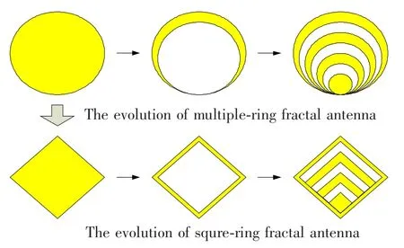
Fig.1 Evolution process of square-nested fractal antenna
The practical monopole antenna with square-nested fractal is a single-plane printed structure,which is shown in Fig.2.The substrate material is adopted FR-4 with relative permittivity εr=4.4 and 1.5 mm thickness.In Fig.2,the dark part is metal and the white part is the substrate.
This monopole antenna can divide into two partsmetal radiator and feeding line.The metal radiator consists of three square metal-loops with different sidelength(l1,l2,l3…)and a square metal-patch,and the four radiation elements share the same feeding vertex.The antenna is fed by CPW,shown in Fig.2,and a 50 Ω SMA is connected with the bottom of CPW.The length of feeding line is 17 mm.

Fig.2 Sketch of the proposed square-nested antenna with associated geometrical parameters
1.2 Antenna Radiation Mechanism
Because the antenna consists of four resonant elements,the multiband radiated characteristic occurs.Fig.3 shows the simulation result of surface current density at feeding point,the current at which is also the input-current for antenna metal-radiator.In the range of 0.5 GHz to 7 GHz,the values of current density around four frequencies,2.1,3.4,5.1 and 5.7 GHz,are much higher,which indicates that there is series-resonant at these frequencies.The simulation results of radiator surface-current at the four frequencies are presented in Fig.4.It can be seen that at 2.1 GHz,currents mainly distribute in the edges of the largest square-loop,whereas at other three frequencies,currents distribute in all three inner elements.Then the following conclusions can be obtained from the surface-current distribution.

Fig.3 Simulated result of radiator input-current.
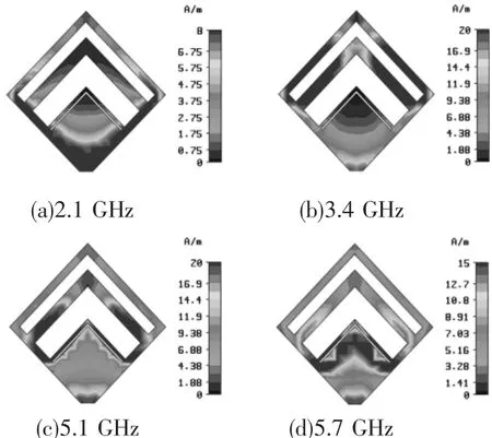
Fig.4 Simulation results of radiator surface-current distribution
1)The largest current at low-frequency distributes in the outermost square-loop.It shows that the size of the largest square-loop correlates with the wavelength of low resonant frequency,which can be used to figure out side-length of the square-loop.
2)Currents chiefly distribute in the edges of square-loops and the edges are some fold lines in Fig.4,which demonstrates that the current distribution is curving.The curving current can make the radiated space fully utilize so that the size of antenna can be miniature.
3)The number of current resonance-point is the same as resonant elements’number,which indicates that,during the design of this kind of antenna;it can adjust the number of radiated element to control the op-erating bands’number.
4)The simulation results also show that the surface currents at the three high-frequencies,as presented in Figs.4(b),4(c)and 4(d),not only distribute in the corresponding radiated element,but also distribute in other elements.This phenomenon can be explained by four radiated elements sharing the same feeding vertex and two square sides,which can cause large coupling between elements and make complex current distribution at high-frequencies,and finally influence the numerical relation between side-length of square-nested element and resonant frequency.The effect will be studied through further simulation.
5)At the four resonant frequencies,distribution of surface current on radiated elements is symmetric versus the central feeding line,and this distribution will cause omni-directional electromagnetic(EM)radiation in far field.What’s more,the EM waves are vertical polarization.As the curving current,cross polarization will also be introduced,which is beneficial to short-distance wireless communication.In addition,there exists similar current distribution at the four frequencies so that the impedance and radiation characteristics are also similar at the four frequencies.Hence,this conclusion and the analysis above are the operating mechanism of this kind of antenna.
2 Antenna Simulation and Measurement
2.1 Design of Printed Monopole Antenna Operating at 2.4/3.5/5.2/5.8 GHz
The experiential formula of deciding antenna size can be established from simulation,which indicates the relation between square side-length and the wavelength of corresponding resonant frequency,as shown in following:

According to formula(1),the structural parameters of this four-band antenna can be set as:l1=16.7 mm,l2=14.6 mm,l3=13.0 mm,l4=11.3 mm,l5=8.0 mm,l6=7.6 mm,l7=7.4 mm,wg=18.5 mm,hg=17.0 mm,ws=42.0 mm,hs=42.0 mm,w=3.0 mm and s=1.0 mm.Fig.5 shows the antenna prototype and the simulation and measurement results are presented in Fig.6.It can be seen from the simulation results that the antenna has four operating bands,2.33 - 2.81 GHz,3.44 -3.54 GHz,5.15 -5.25 GHz and 5.71 -6.22 GHz,respectively,while in measurement results,the three bands are 2.20-2.89 GHz,3.49-3.79 GHz and 4.93-6.01 GHz with corresponding impedance bandwidth 27.1%,8.2%and 19.7%,respectively.The bandwidths can meet the requirement of WLAN and WiMAX communication.Antenna radiation patterns have been measured by Agilent E8362B Vector Network Analyzer in anechoic chamber and the experimental results are presented in Fig.6,from which the radiation patterns can achieve omni-directionality in H-plane in individual operating band.Except the lowest frequency,simulation radiation pattern in H-plane is not a Centro symmetric circle but an ellipse because of two reasons.The first reason is the influence of PCB substrate.The radiators are printed on the single-side so that the radiating electromagnetic waves would be interfered by substrate’s reflection and refraction,the effect of which is worse at high frequency.Secondly,all the three inner radiators are sheltered by outer radiators,so radiation is poor in these two shelter parts,which makes radiation pattern present ellipse in H-plane.
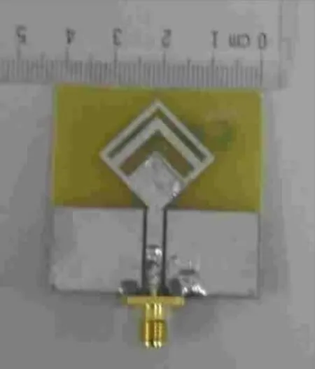
Fig.5 Prototype of square-nested fractal monopole antenna
Due to the effect of actual substrate materials and experimental conditions,there is little error between the measurement results and the simulation results.The measurement reflection coefficient is lower than the simulation values in the range 1.0-5.7 GHz,but a bit higher in 5.8-7.0 GHz.And because of the decrease of measurement reflection coefficient,operating bands at central frequency 5.2 GHz and 5.8 GHz,respectively, combine together. So the measurement bandwidth is from 4.93 GHz to 6.01 GHz with reflection coefficient lower than-10 dB.However,we find outthatthere are two resonantfrequencies in Fig.6(a),which is actually caused by dielectric loss.The dielectric material used in the prototype is FR-4 with tangent of dielectric loss angle(tan δ)0.02,which is a lot bigger than that of RO4350B(about order of 10-3).After the transmission from feeding-line to feeding port,the radiators’input reflection-power would decrease,as well as the reflection coefficient.It also indicates the dielectric loss of feeding-line mainly reduces the reflection coefficient.Moreover,the loss materials definitely possess the dispersion characteristic and the higher frequency is,the more obvious dispersion characteristic is.In practice,the actual dielectric materials are inhomogenous and the discontinuities of welding part of SMA connector and feeding-line would also influence the reflection coefficient.All the above factors can cause errors for reflection coefficient between the experimental results and the simulation results.
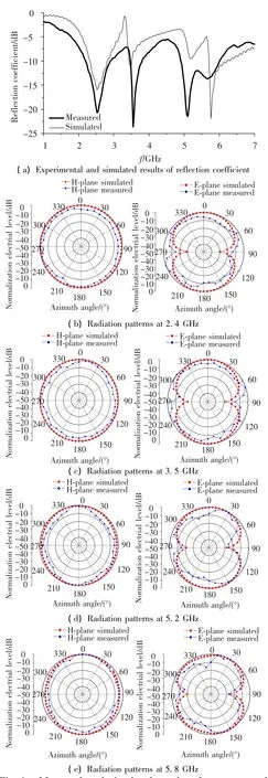
Fig.6 Measured and simulated results of square-nested fractal monopole antenna
In addition,the dielectric loss and experimental conditions would also influence the measurement radiation patterns.The substrate’s inhomogeneity may cause the asymmetry of antenna patterns and the clamp in the bottom of prototype would influence the measurement results of E-plane radiation patterns.But for the proposed antenna in this paper,the omni-directional characteristic in H-plane is the most important.The experimental results present that H-plane’s out-ofroundness of the proposed monopole antenna is less than 8 dB,which can be accepted in the fields of short-distance wireless transmission.What’s more,the experimental results also show that when frequency is not higher than the upper-limit of S band,adopting FR-4 materials can obtain the similar performance of simulation,which is under the ideal conditions.But when frequency grows up,the antenna performance would be poor.Notwithstanding,the monopole antenna can be applied in short-distance wireless transmission.
2.2 Design of Printed Dipole Antenna Operating at 2.4/5.2/5.8 GHz
For the proposed monopole antenna above,the limitation of the ground size would cause the asymmetry of E-plane radiation patterns and influence the maximum gain of H-plane.In order to solve this problem,enlarging ground size and adopting dipole antenna are the two feasible methods.But adding ground size would increase the total antenna size and make against antenna miniaturization,and adopting dipole antenna would face the difficulty of balance-feeding.
Commonly,the SMA connector is a kind of coaxial line and an unbalance feeding structure.Dipole antenna requires the balanced feeding and balanced microstripline[16]is a kind of transmission line with balanced structure,which has been widely applied into the feeding part of printed dipole antenna.A divided balancer has been introduced in the feeding part in Refs.[17]and[18],but this method would reduce antenna bandwidth and not be suitable for UWB and multiband antenna’s feeding.In this paper,a method ofcoaxial-line-to-quasi-microstripline-to-balanced-microstripline is proposed to solve this problem.In Fig.7,the width of the quasi-microstripline is nearly equal to that of the ground.The balanced microstripline consists of two metal-belts with the same width,which are printed on two sides of the substrate,respectively.With the transition of quasi-microstripline,the transmission line connected with two arms of the dipole becomes balanced microstripline,which can make the feeding to be balanced.What’s more,printed dipole antenna mostly is printed on both sides of the substrate,but this would cause two arms of the dipole to be non-coaxial and damage the symmetry of radiation patterns.In order to prevent this phenomenon,in this paper,two arms of the dipole are printed on the same side of the substrate:one arm is directly connected with one branch of balanced microstripline and the other arm is connected with the other branch on another substrate side through an extended belt and a metal via-hole,as shown in Fig.8.In addition,because the two feeding points of the dipole are so closed and the substrate is so thin,the extension and metal via-hole would not cause much additional phase-shift and impedance change.Meanwhile,the electric potentials of the two poles are equiamplitude and reverse-phase.

Fig.7 Sketch of the proposed square-nested dipole antenna
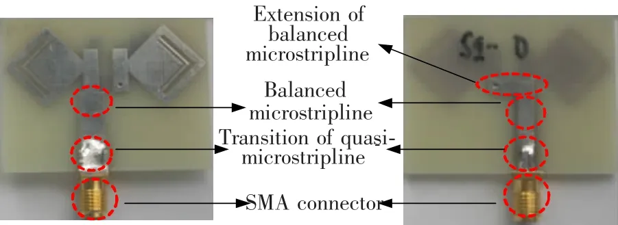
Fig.8 Feeding structure of square-nested dipole antenna
The analysis process of antenna radiation mechanism is similar to the monopole antenna above and the final designed antenna radiation element consists of three square-nested elements,which can achieve triband characteristics.The optimal values of antenna parameters obtaining from the simulations are:l1=12 mm,l2=9.2 mm,l3=8.2 mm,l4=7.6 mm,l5=7.3 mm,wg=5 mm,hg=22 mm,ws=45 mm,hs=40 mm,w=3 mm,h=9 mm,hf=25 mm,wf=3 mm and lf=9 mm.The prototype,as shown in Fig.9,has been manufactured and measured in the microwave anechoic chamber and both the experimental results and the simulation results are presented in Fig.10.The simulation operating bandwidths are 2.29-2.71 GHz,5.12-5.25 GHz and 5.75-5.97 GHz with relative bandwidths 16.8%,2.5%and 3.75%,respectively.The experimental operating bandwidths are 2.37-2.76GHzand 4.99-6.21 GHzwith relative bandwidths 15.2% and 21.8%,respectively.Moreover,it can be seen that the antenna radiation patterns can achieve omnidirectional in H-plane.The experimental results well match the simulation results.

Fig.9 Prototype of square-nested fractal dipole antenna
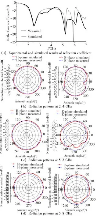
Fig.10 Measured and simulated results of square-nested fractal dipole antenna
Also,similar to the analysis of the proposed monopole antenna,the dielectric loss,inhomogeneity and dispersion are the chief factors causing errors between the experimental results and the simulation results in the high-frequency band.But both the results indicate that,due to antenna’s symmetry,the pro-posed antenna is horizontal polarization and the maximun radiation direction is consistent with the orientation which is vertical with the polarization direction.Compared with the proposed monopole antenna,the electric-level parameters of the dipole antenna is about 4-8 dB higher in the maximum radiation direction.
From the above analysis,both the proposed monopole antenna and dipole antenna are coplanar printed antennas and the ratio(K)of the maximum dimension of antenna radiator to wavelength of the lowest operating frequency is 0.134 and 0.173,respectively.Tab.1 shows the comparison between the proposed antennas and other references,which indicates that the proposed antennas possess obvious characteristic of miniaturization.What’s more,adopting the printed transmission lines for feeding,such as CPW and balanced microstripline,can make the antennas more easily integrate into the communication systems and has promising future of application in WLAN and WiMAX.
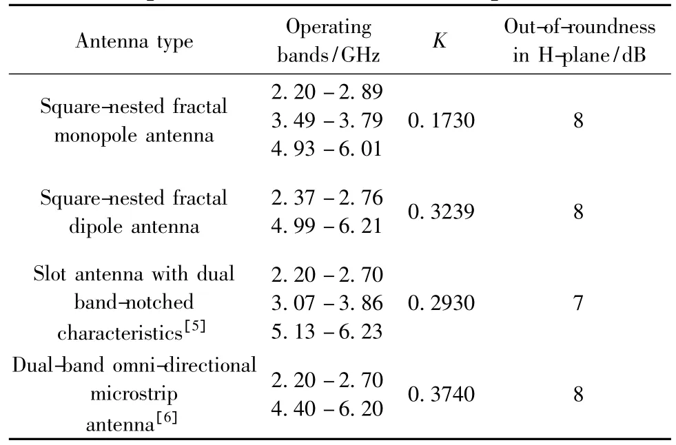
Tab.1 Comparison of multiband antennas’performance
3 Conclusions
A kind of novel square-nested fractal antennas are proposed and designed,which are nested with a series of similar square-loops.The antennas are simulated by CST MICROWAVE STUDIO®and the results show that both the side-length of square-loop and number of nesting square-loops can control the central frequency of bandwidth and its number.A monopole multiband antenna and a printed square-nested dipole antenna fed by balanced microstripline are designed to cover the four bands at 2.4/3.5/5.2/5.8 GHz,which are required by WLAN/WiMAX systems.Prototypes of the two antennas have been manufactured and measured and the experimental results well match the simulation results.In addition,the antenna size is small in the main polarization direction,which is easy for integrating into WLAN and WiMAX systems.
[1]Pal A,Behera S,Vinoy K J.Design of multi-frequency microstrip antennas using multiple rings.IET Microwaves,Antennas& Propagation,2009,3(1):77-84.
[2]Mirkamali A,Akhoondzadeh-Asl L,Hall P S,et al.Modified multiband multiple ring monopole antenna.Progress In Electromagnetics Research C,2010,14:173-183.
[3]Liao W J,Chang S H,Li L K.A compact planar multiband antenna for integrated mobile devices.Progress In Electromagnetics Research,2010,109:1-16.
[4]Hamid M R,Gardner P,Hall P S,et al.Multimode vivaldi antenna.Electronics Letters,2010,46(21):1424 -1425.
[5]Li F,Ren L S,Zhao G,et al.A compact microstrip-linefed slot antenna with dual band-notched characteristics for WLAN/WiMAX applications.Progress In Electromagnetics Research Letters,2010,16:89 -97.
[6]Tze-meng O,Geok T K,Reza A W.A dual-band omni-directional microstrip antenna.Progress In Electromagnetics Research,2010,106:363-376.
[7]Singh A K,Meshram M K.Shorting pin loaded dual-band compact rectangular microstrip antenna.International Journal of Electronics,2007,94(3):237 -250.
[8]Ressiguier D,Costantine J,Tawk Y,et al.A reconfigurable multi-band microstrip antenna based on open ended microstrip lines.EuCAP,3rd European Conference on Antennas and Propagation.Berlin.2009.792-795.
[9]Krishna D D,Gopikrishna M,Anandan C K,et al.CPW-fed koch fractal slot antenna for WLAN/WiMAX applications.IEEE Antennas and Wireless Propagation Letters,2008,7:389-392.
[10]Kimouche H,Zemmour H,Atrouz B.Dual-band fractal shape antenna design for RFID applications.Electronics Letters,2009,45(21):1060 -1063.
[11]Mehdipour A,Rosca I D,Sebak A R,et al.Full-composite fractal antenna using Carbon Nanotubes for multiband wireless applications.IEEE Antennas and Wireless Propagation Letters,2010,9:891 -894.
[12]Ghatak R,Poddar D R,Mishra R K.Design of Sierpinski gasket fractal microstrip antenna using real coded genetic algorithm.IET Microwaves,Antennas & Propagation,2009,3(7):1133-1140.
[13]Azaro R,Zeni E,Gazzini T,et al.Synthesis of a three-dimensional triband(L1-L2 GPS and Wi-Fi)prefractal tree antenna. Microwave and OpticalTechnology Letters,2007,49(9):2114-2118.
[14]Sinha S N,Jain M.A self-affine fractal multiband antenna.IEEE Antennas and Wireless Propagation Letters,2007,6:110-112.
[15]Song C T P,Hall P S,Ghafouri-Shiraz H.Multiband multiple ring monopole antennas.IEEE Transactions on Antennas and Propagation,2003,51(4):722-729.
[16]Simons R N,Lee R Q,Perl T D.Non-planar linearly tapered slot antenna with balanced micro-strip feed.Antennas and Propagation Society International Symposium,1992.AP-S.1992 Digest.Held in Conjuction with:URSI Radio Science Meeting and Nuclear EMP Meeting,IEEE.Piscataway:IEEE.1992.2109-2112.
[17]Chuang Huey-Ru,Kuo Liang-Chen.3-D FDTD design analysis of a 2.4 GHz polarization-diversity printed dipole antenna with integrated balun and polarization-switching circuit for WLAN and wireless communication applications.IEEE Transactions on Microwave Theory and Techniques,2003,51(2):374 -381.
[18]Kouzaki T,Kimoto K,Kubota S,et al.Quasi yagi-uda antenna array for detecting targets in a dielectric substrate.IEEE International Conference on Ultra-Wideband.Piscataway:IEEE.2009.759-762.
 Journal of Harbin Institute of Technology(New Series)2012年6期
- Journal of Harbin Institute of Technology(New Series)的其它文章
- Load distribution of involute gears along time-varying contact line
- High-gain planar TEM horn antenna fed by balanced microstrip line
- Spatially localized and joint access point selection for Wi-Fi indoor positioning
- Research on the Seebeck effect in efficient turning process and improving tool life
- A reliable and high throughput hybrid routing protocol for vehicular ad-hoc network
- An innovative detection method of high frequency BPSK signal with low signal-to-noise ratio