Investigation of support interference on rotary balance test in FL-8low speed wind tunnel
2012-11-15 09:31GAOJianjunLIUChunmingBUChen
实验流体力学 2012年1期
GAO Jian-jun,LIU Chun-ming,BU Chen
(1.Beijing University of Aerodynamics and Astronautics,Beijing 100191,China;2.China Aerodynamics Research Institute of Aeronautics,Harbin 150001,China)
0 Introduction
The two existing rotary balances in domestic wind tunnel are both with the type of model supporting rod mounted on the arc orbit.To assure the intensity and rigidity at high rotational rate,and to diminish the influence of deformation and vibration,the arc orbit and the model supporting rod are generally thick and strongly disturb the flow field[1].The downward development of asymmetric vortices shed from the model at high angle of attack might be disturbed by these supports,as shown in Fig.1.The rotations were steady at low rotational rate,so is the interference.The vortices inclined towards the increase of rotational rate,stroke on the arc orbit at a certain combination of angle of attack and sideslip,or sometimes they did not.These made the law of support interference vary differently.
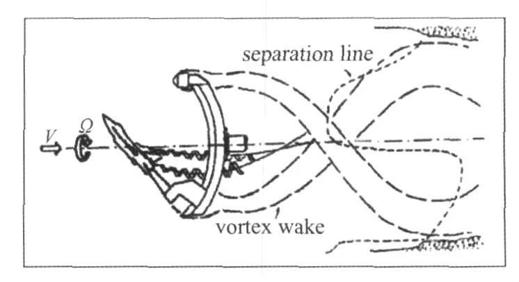
Fig.1 Sketch of support interference on rotary balance test图1 旋转天平支架干扰示意图
Furthermore,vortices shed from model and supports combined into spiral wake.The wake and the wind tunnel wall interfered with each other,which made the flow speed at a fix point near the wall vary periodically,and caused the separation of the boundary layer.The position of separation line translated in the direction of the rotational wake and oscillated along wind tunnel centre line at the same time.The wake block effect and pressure gradient of the upstream also fluctuated periodically,influenced the flow near the model and arc orbit and varied the vortices and wake of the model.The unsteadiness effect of the interference from model-support-wind tunnel wall were too complicated to be simulated.
1 Analysis
The support interference problems of rotary balance test were generally divided into three portions:
(a)main shaft and its support.These parts of configurations were far from downstream of the model and kept actionless in the test.So it had little influence to the flow field,and the interference could be neglected.
(b)arc orbit,slide carriage,counterweight,etc.These parts of configurations were near the downstream of the model and with large volume.The high rate rotation of these configurations caused pre-rotation in the flow field in model area,affected the accuracy of rotary balance test seriously,so their interference must be measured.
(c)rear sting or dorsal rod.The rod especially the dorsal rod was attached to the model and destroyed the flow field.According to the research of rotary balance test support interference in the UK,the dorsal rod could change the slope of result curves in some angle of attack,so it was the key problem of the research.
Based on the analysis above,this paper presented the interference measurement method of support,such as arc orbit,slide carriage,counterweight,rod,etc.
2 Support interference measurement
“Two-step method”was used in the measurement of support interference in rotary balance test.The key of“two-step method”was the development of a new support device that can realize the function of original system[2],and could obtain the support interference by computing the difference of the test results with and without the original system.
2.1 Device design
The support interference measurement system was composed of main cone,new variable angle rod and the mirror configuration of original rotary balance as shown in Fig.2.The main cone was the main connector of the whole configuration and there were rear cone,fore cone and double-ear on it.The rear cone conjugated to the main shaft of rotary balance,the fore cone connected to the new variable angle rod,and the double-ear mounted to the mirror configuration of original rotary balance.
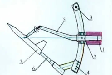
Fig.2 Sketch of support interference measurement图2 支架干扰测量简图
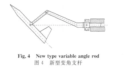
The new type variable angle rod not only substituted arc orbit to support the model,but also realized the variation of angle of attack and sideslip.The mirror configuration of original rotary balance,designed as the original shape and size,protruded from the inside of the model but not touching it.These structure simulated the interference characteristics.
2.2 Variable angle rod and its principle
The new type variable angle rod was a set of bend rod that dorsally supported the model as shown in Fig.3.The rod was composed of fore bar,rear bar and three variable angle joints.The maximum angle of attack and sideslip were determined by the angle between the fore bar and the wind tunnel centre line.The pitch joint at foreside and the roll joint were used to modulate the angle of attack and sideslip of model,and the pitch joint at backside was used to compensate the angle between the plane which was determined by the model centre line,the wind tunnel centre line and the plane of mirror configuration.
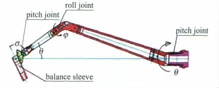
Fig.3 Configuration of new type variable angle rod图3 新型变角度支杆结构图
It was assumed that the angle between fore bar axis and the wind tunnel centre line wasθ,the angle between fore bar axis and the model centre line wasσ,shown in Fig.3 ,the rotational angle of fore bar wasφ,and the rotational angle of rear bar wasΦ,then we could obtain the attitude angles of the modelαandβ:

The value ofθwas determined by the compromise of maximum angle of attack and sideslip.
It could be deduced that the variable scope ofαwas determined by that ofσfrom the formula above,so the modulated angle of the new type support rod had almost covered the whole range in rotary balance test.
3 Data processing method
It was assumed that the interference of a certain component was isolatable,so that the interference could be obtained by computing the difference of the forces with and without that object.The components involved in the data processing were new type variable angle rod,arc orbit,rear sting and dorsal rod,etc.
4 Test results

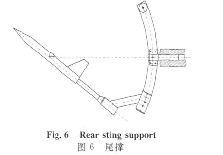

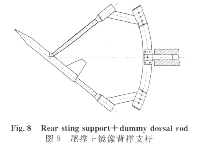
The support interference of longitudinal forces was symmetrical to the vertical axis,i.e.,the values of support interference were almost the same.The influence on normal force made it vary in one way.The rear sting that stood near the back of the model made the normal force increase slightly,and the rest,such as arc orbit,dorsal rod,made it decrease.The larger the component,the stronger the influence was,see Fig.9.
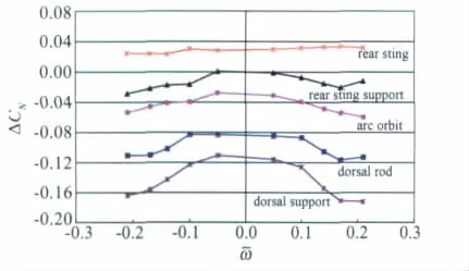
Fig.9 Support interference,ΔCN-ω图9 法向力支架干扰
The axis force was essentially approximate zero at high angle of attack,and so was the support interference.It had little influences upon the aerodynamic characteristics,as shown in Fig.10.
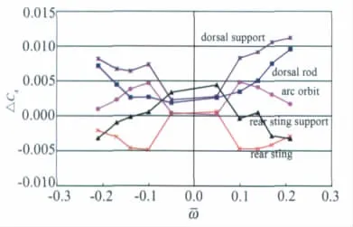
Fig.10 Support interference,ΔCA-ω图10 轴向力支架干扰
The main factor that affectd the pitching moment was the volume of the support.The influences of arc orbit,dorsal support and rear sting were decreased along with the decrement of their volumes,see Fig.11.
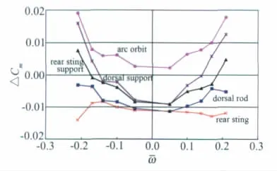
Fig.11 Support interference,ΔCm-ω图11 俯仰力矩支架干扰
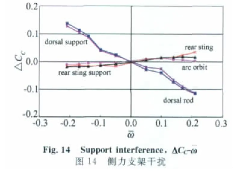
It could be found from Fig.12 to Fig.14 that the effects were symmetry about the origin of coordinate,and the two extremeness were arc orbit and the dorsal rod.The arc orbit had the trend of increasing the roll stability,and the dorsal rod was on the contrary.The performances of support interference on yawing moment were similar to the normal force,and there were some inherent relationships among them.The number and the volume of the support on the backside of the model had determined the degree of influences.The sequence of influences from serious to slight was dorsal support,dorsal rod and arc orbit.The rear sting had the reverse influence.All of the support components had little effects on the side force except dorsal support rod.
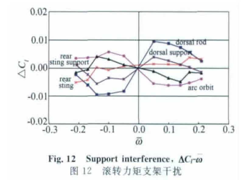

In summary,the rear sting had the least support interference.
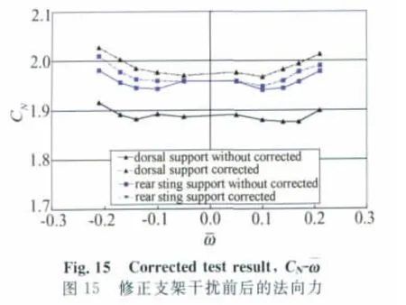

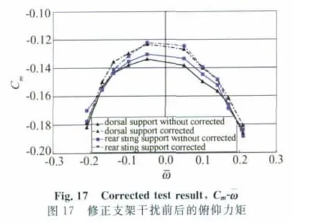

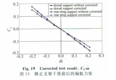

Fig.20 Corrected test result,CC-ω图20 修正支架干扰前后的侧力
The results on rear sting and dorsal support test were shown in Fig.15 to Fig.20.Some components,such as the normal force and the pitching moment,were corrected in the same direction that made the final results closer.The others were corrected to the midst from obvious differences.General speaking,the final aerodynamic forces on different support were the consistent.It could be concluded that the corrections were reasonable.
5 Conclusions
(1)Test results at typical angle of attack and sideslip showed that,the support interference correction of rotary balance test improved the accuracy of test results greatly,and the results at other attitudes of model showed the same trend.
(2)There was no valid method to correct the interference of the support facilities far behind the model at present.It might be solved by tension wire support method aftertime.
[1]LI Zhoufu,LI Qian,CHEN Yu,et al.Special test techniques in wind tunnel[M].Beijing:Aviation Industry Publishing.2010.
[2]BU Chen,DU Xiqi,HUANG Lijing.Studies of unsteady lateral aerodynamic characteristics of aircraft for the large amplitude rolling movements in rotational flow field[J].Journal of Experiments in Fluid Mechanics,2008,22(1):46-48.
[3]ERICSSON L E.Another look at high alpha support interference in rotary tests[R].AIAA 91-0682,1991.
[4]BEYERS M E.Unsteady wind tunnel interference in dynamic testing[R].AIAA 91-0682,1991.
猜你喜欢
浙江共产党员(2022年10期)2022-11-23
中学生数理化·八年级物理人教版(2021年12期)2021-12-31
中学生数理化·八年级物理人教版(2020年12期)2021-01-18
数学小灵通(1-2年级)(2020年9期)2020-10-27
当代贵州(2019年41期)2019-12-13
中学生数理化·高一版(2019年3期)2019-04-15
少年漫画(艺术创想)(2018年2期)2018-09-11
中学生数理化·八年级物理人教版(2014年2期)2014-04-02
环球时报(2009-11-05)2009-11-05
环球时报(2009-09-09)2009-09-09