
A broad-band sub-harmonic mixer for W-band applications
2013-01-08 08:26XuZhengbinQianCheng
Xu Zhengbin Qian Cheng
(State Key Laboratory of Millimeter Waves,Southeast University,Nanjing 210096,China)
As we have known, sub-harmonic mixers are widely used in the millimeter-wave system. Compared with the fundamental mixer, the most outstanding characteristic of the sub-harmonic mixer is reducing the demands on the LO source, which is very useful in millimeter-wave band. In addition, by using anti-parallel diode pair (APDP), the sub-harmonic mixer has many other attractive advantages, such as better RF-to-LO isolation, simple RF diplexing, and inherent LO noise suppression.
Millimeter-wave sub-harmonic mixers in bilateral fin-line or waveguide have been reported in much literature[1-2]. Those mixers achieve a low conversion loss, which is comparable with the conversion loss of the fundamental mixers. However, their inherent structures make them unsuitable for integrating with other planar circuits, such as low noise amplifier (LNA), LO multiplier, to form a compact transceiver. In the past decades, many sub-harmonic mixers in form of monolithic microwave integrated circuit (MMIC) for millimeter-wave applications have been reported[3-5]. However, to the authors’ knowledge, commercial MMIC sub-harmonic mixers for W-band applications are not yet available. On the other hand, the development of a customized MMIC mixer tailored to the specific requirements for a particular practical application is a time-consuming and expensive task. In these instances, full planar microstrip hybrid microwave integrated circuit (MIC) mixer employing discrete diodes can achieve high-level system performance and better cost effectiveness beyond what is possible using MMIC devices.
The most important part in the design of a sub-harmonic mixer is to provide suitable terminations at both ends of the APDP for the RF, LO and IF signals. In the conventional sub-harmonic mixer configuration[6], open and short stubs are used to provide return pass for the RF, LO, and IF signals and form port-to-port isolation. However, as the operating bandwidth (either RF or IF bandwidth) increases, the condition provided in Ref.[6] is no longer satisfied, which can result in the performance deterioration of the conventional sub-harmonic mixer. On the other hand, it is hard to realize the edge-coupled band-pass filter which is commonly used in the conventional sub-harmonic mixer with a common microstrip fabrication process at W-band.
In this paper, we develop a broad-band sub-harmonic mixer for W-band applications by exploiting standard microstrip hybrid MIC technology. A novel embedding network is proposed for the broad-band W-band sub-harmonic mixer design. CAD tools are used for simulating and optimizing the performance of the mixer. The measurement results show that the proposed mixer achieves a conversion loss of 9 to 13.7 dB over the 80 to 107.5 GHz frequency band. The simultaneous IF bandwidth of the proposed sub-harmonic mixer can be up to 18 GHz, which is essential for the broad-band millimeter-wave system applications.
1 Circuit Configuration
The circuit configuration of the proposed sub-harmonic mixer is shown in Fig.1. It consists of an APDP, a low-pass filter, a band-pass filter, and a diplexer. The RF signal is applied from the left side of the APDP. The LO signal is applied from the right side of the APDP, while the IF signal is taken out from the right side of the APDP. The diplexer is employed to separate the LO signal and IF signal from each other. A band-pass filter usingλ/4 shunt stubs andλ/4 connecting lines is adopted to provide a wide pass band for the RF signal and a stop band for the LO and IF signals. Choosing the length of the transmission line ML1properly, a short-circuited terminal for the LO and IF signals at the left side of the APDP can be achieved. The band-pass filter also provides a return path for the DC signal that results in the unbalance of the APDP. On the right side of the APDP, the low-pass filter is used to reject the RF signal and pass the LO and IF signals with low insertion loss. Inserting a transmission line (ML2) of proper length, the low-pass filter provides a short-circuited terminal on the right side of the APDP for the return path of the RF signal applied to the diode pair.
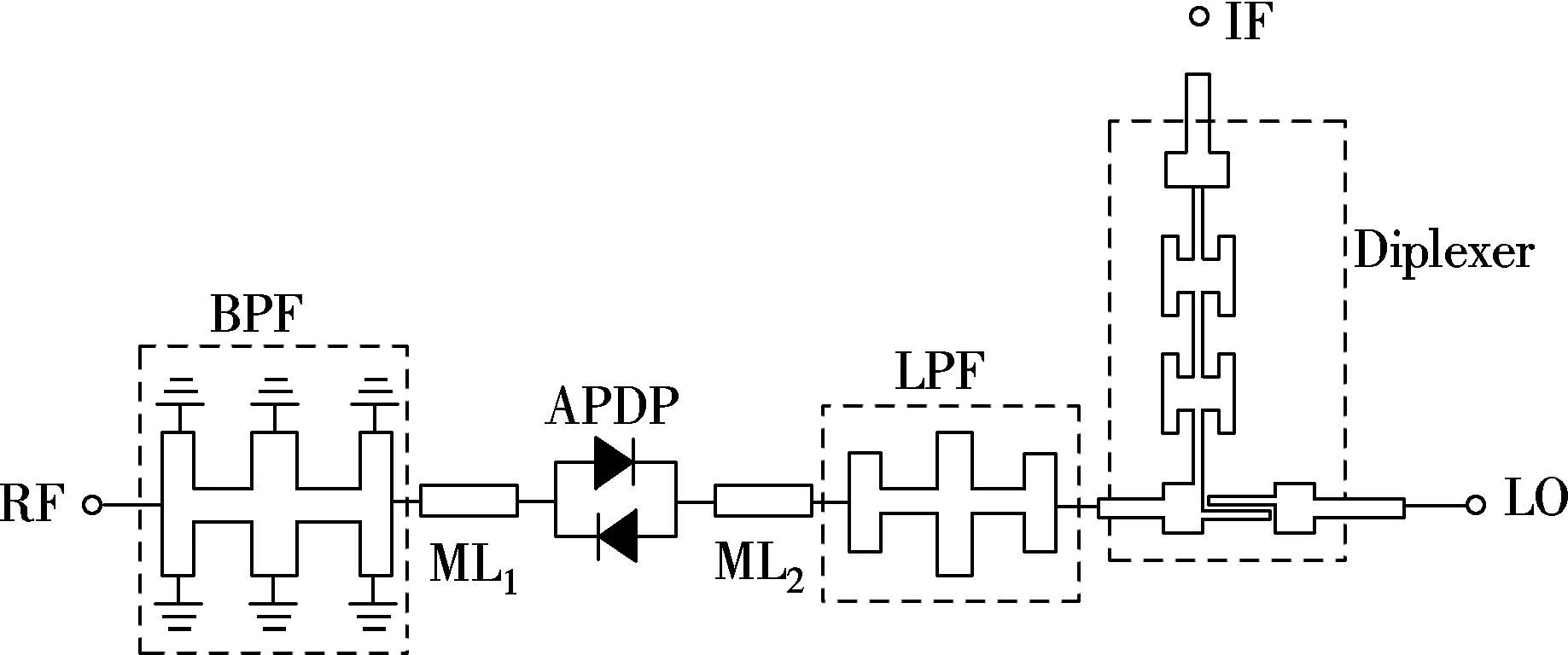
Fig.1 Circuit configuration of proposed sub-harmonic mixer
The diplexer consists of a hammer head low-pass filter and an edge-coupled band-pass filter. For broad-band edge-coupled band-pass filers, the coupling at the end section is very tight so that the gaps become physically unrealistic[7]. To alleviate this problem, a stepped impedance resonator (SIR) with an uncoupled end is used in the edge-coupled band-pass filter, as shown in Fig.1. To achieve a high cut-off frequency of the hammer head low-pass filter, the capacitance introduced by the SIR is absorbed into the hammer head low-pass filter. The diplexer is simulated and optimized by Ansoft HFSS. The simulation results are shown in Fig.2. Port 1, 2 and 3 correspond to the common, LO and IF port, respectively. The substrate used in the simulation is 5-mil-thick Rogers RT/duroid 5880). As Fig.2 shows, the cut-off frequency of the hammer head low-pass filter is about 18 GHz and the band width of the edge-coupled filter is about 6.5 GHz at the center frequency of 43 GHz.
The band-pass filter usingλ/4 shunt stubs andλ/4 connecting lines is designed by the equations given in Ref.[8]. The pass band of the filter is chosen from 75 to 160 GHz. Its performance is optimized by Ansoft HFSS over the frequency band of 80 to 100 GHz which is the RF frequency band we are interested in. Many types of low-pass filters can be used for designing the proposed mixer. However, as the insertion loss and the fabricating complexity are concerned, an open circuited stubs low-pass filter is used in this paper. The cut-off frequency of the low-pass filter is set at 50 GHz and the rejected band is from 80 to 120 GHz.
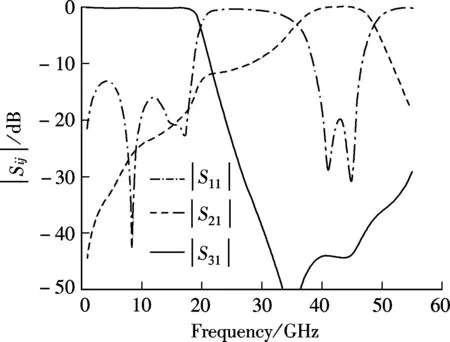
Fig.2 Simulated frequency response of the diplexer
The diode pair used here is a commercial GaAs Schottky barrier flip-chip diode, whose part number is DMK2308 from Skyworks, Inc. Parameters of the diode are given in Tab.1. As the cut-off frequency of the diode is about 455 GHz, it may cause a little performance degradation of the mixer at W-band. In order to determine the effect of the diode packaging, the diode chip structure is modeled by Ansoft HFSS according to the coaxial probe method presented by Hesler[9], and 4-portS-parameters are calculated to represent the effect of the diode packaging.

Tab.1 Parameters of DMK2308 (per junction)
The complete mixer circuit is simulated by the harmonic-balance analysis module of the Agilent Advanced Design System (ADS). The frequency response of the passive elements discussed above is represented byS-parameters, which are calculated by Ansoft HFSS, and imported to ADS as an sNp file. Then, the lengths of microstrip are added to the circuit to connect those sNp modules according to the schematic of the proposed mixer. The performance of the mixer is optimized by tuning the length of the microstrip line.
The proposed mixer is designed and fabricated using 5-mil-thick RT/duroid 5880 substrate (εr=2.2) and mounted in a splited copper housing, as shown in Fig.3. A large ground plane is placed on the signal layer to provide a perfect grounding for the band-pass filter. In order to match the interfaces with the test system, the RF port and LO port are WR-10 and WR-22 waveguide, respectively, and the IF port is subminiature A (SMA) coaxial connector. The RF signal is transferred from the waveguide to the microstrip by utilizing a waveguide-finline-microstrip transition which introduces an insertion loss of approximately 0.7 dB. The LO signal is coupled from the waveguide by means of an E-plane probe whose insertion loss is about 0.5 dB.
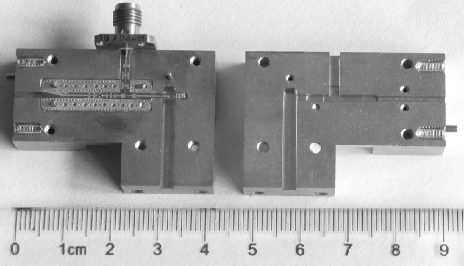
Fig.3 Photograph of the fabricated sub-harmonic mixer
2 Results and Discussion
The down-conversion loss of the proposed sub-harmonic mixer is measured. An Agilent signal generator E8267C with a millimeter-wave source module is used to provide the RF signal over the frequency range of 75 to 110 GHz. An active frequency doubler driven by an Agilent signal generator E8257D is used to provide LO signal from 40 to 48 GHz. The output power of the frequency doubler is calibrated with a power meter. The IF output power is measured using an Agilent E4440A spectrum analyzer whose power display is calibrated with a power meter.
Fig.4 illustrates the measured down-conversion loss of the mixer as a function of RF frequency. The measurements are done with an LO frequency fixed at 43 GHz and an LO power of 13 dBm. The conversion loss of 10.7 to 13 dB (the insertion loss of waveguide-finline-microstrip is calibrated out) is observed within an RF bandwidth from 80 to 104 GHz, which means that the simultaneous IF bandwidth of the mixer can be up to 18 GHz. A comparison between simulated and measured results is also shown in Fig.4 and a good agreement is observed. A little difference between the measurement and simulation may be caused by the fabrication errors. Measured conversion loss vs. RF frequency with IF frequency fixed at 3 GHz and 12 GHz are shown in Fig.5. With the LO power level of 13 dBm, a conversion loss less than 13.5 dB from 83 to 99 GHz with IF fixed at 3 GHz and a minimum conversion loss about 9 dB at a RF of 92.5 GHz can be seen from Fig.5. Furthermore, a conversion loss of 10.7 to 13.7 dB from 92 to 107.5 GHz with IF fixed at 12 GHz can also be seen from Fig.5. Fig.6 shows the dependence of conversion loss on LO power. Limited by the output power of the frequency doubler, the measured result is given only up to 13 dBm. Simulations show that the conversion loss is weakly dependent on LO power when the LO power level is over than 13 dBm.
Comparisons of the proposed sub-harmonic mixer with other similar published works[10-13]are summarized in Tab.2. The results show that the performance of our proposed sub-harmonic mixer is comparable to the best perf-ormance of similar mixers published so far. Moreover, if a diode pair with higher cut-off frequency is used in the proposed mixer, its performance can be better. As the common PCB technology and commercial schottky diode pair are employed in the proposed mixer, its cost is low. Compared with the mixer presented in Refs.[12-13], which also employs the microstrip hybrid MIC technology, the mixer proposed in this paper shows better performance.
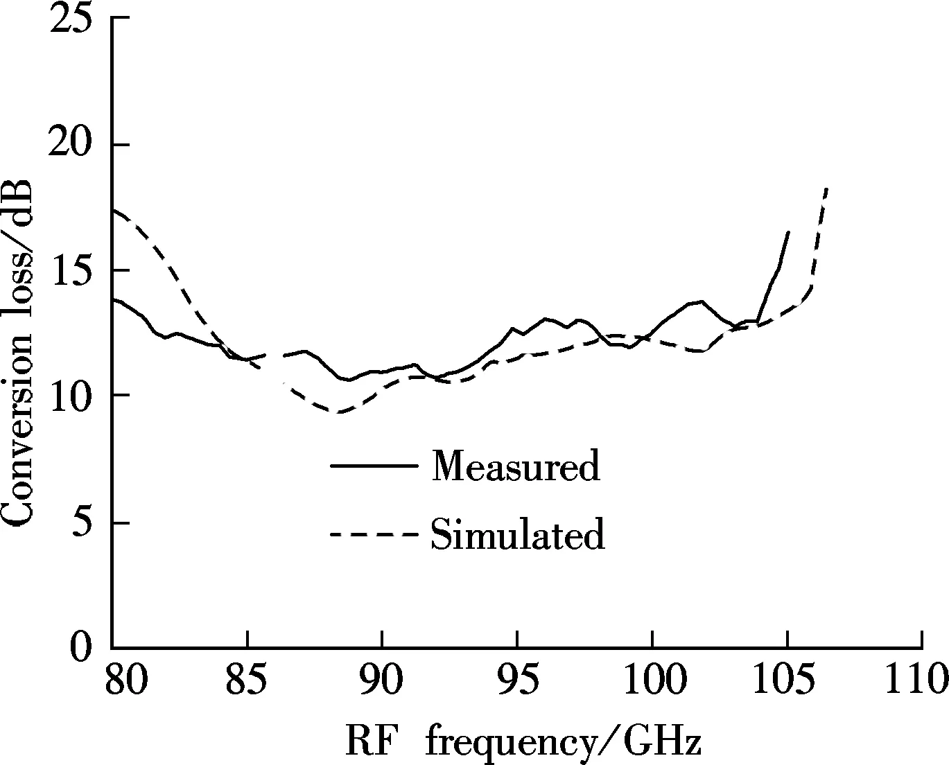
Fig.4 Comparison of simulated and measured down-conversion loss
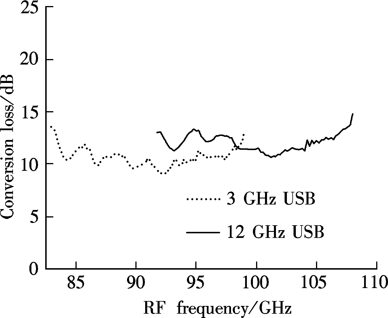
Fig.5 Relationship between conversion loss and RF frequency
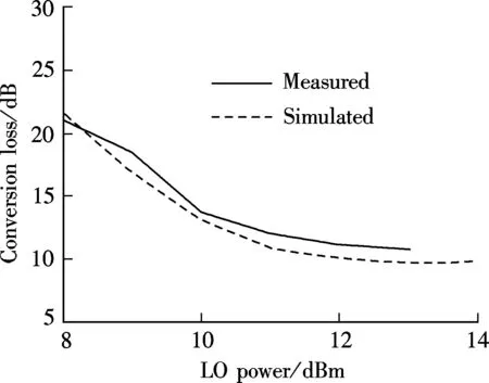
Fig.6 Relationship between conversion loss and LO power
3 Conclusion
A sub-harmonic mixer has been realized for W-band applications by using microstrip hybrid MIC technology. Replacing the open and short stubs that are used in the convertional sub-harmonic mixer with a band-pass filter and a low-pass filter, respectively, a wide operating freq-uency band is achieved. Measurements show that the performance of the proposed sub-harmonic mixer is comparable to the best performance of similar mixers published so far. Meanwhile, the proposed mixer maintains a low cost property. Furthermore, as the proposed sub-harmonic mixer is purely a planar circuit, it can be easily integrated with other planar circuits to obtain a high-performance, low-cost, compact millimeter-wave front-end.
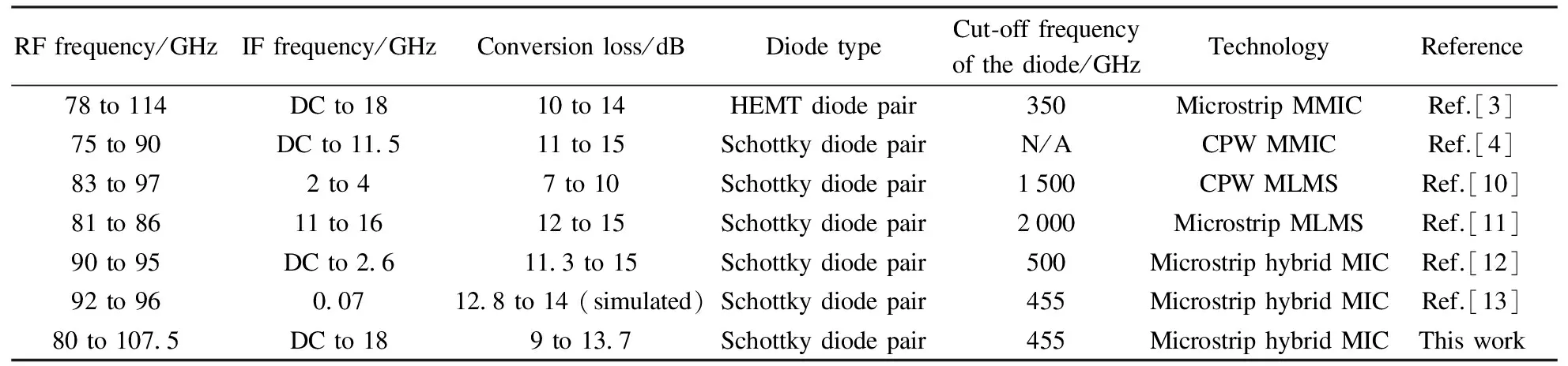
Tab.2 Comparison of published sub-harmonic mixers
[1]Meier P J, Calviello J A, Bie P R. Wide-band subharmonically pumped W-band mixer in single-ridge fin-line [J].IEEETransactionsonMicrowaveTheoryandTechniques, 1982,23(12): 2184-2189.
[2]Tahim R S, Pham T, Chang K. Millimetre-wave micro-strip subharmonically pumped mixer [J].ElectronicsLetters, 1985,21(19): 861-862.
[3]Huang Y J, Lien C H, Wang H, et al. A 78-114 GHz monolithic subharmonically pumped GaAs-based HEMT diode mixer [J].IEEEMicrowaveandWirelessComponentsLetters, 2002,12(6): 209-211.
[4]Dyadyuk V, Archer J W, Stokes L. W-band GaAs schottky diode MMIC mixers for multi-gigabit wireless communication [C]//Proceedingsof2ndInternationalConferenceonWireless,BroadbandandUltraWidebandCommunications. Sydney, Australia, 2007: 27-30.
[5]Kanaya K, Kawakami K, Hisaka T, et al. A 94 GHz high performance quadruple subharmonic mixer MMIC [C]//IEEEMTT-SInternationalMicrowaveSymposiumDigest. Seattle, MA, USA, 2002: 1249-1252.
[6]Iton K, Iida A, Sasaki Y, et al. A 40 GHz band monolithic even harmonic mixer with antiparallel diode pair [C]//IEEEMTT-SInternationalMicrowaveSymposiumDigest. Boston, MA, USA, 1991: 879-882.
[7]Xu Z B, Qian C, Dou W B, et al. Design of a W-band sub-harmonic mixer by employing microstrip technology [J].JournalofInfraredandMillimeterWave, to appear.
[8]Matthaei G, Young L, Jones E M T.Microwavefilters,impedance-matchingnetworks,andcouplingstructures[M]. NewYork: McGraw-Hill, 1964: 595-605.
[9]Hesler J L. Planar schottky diodes in submillimeter-wavelength waveguide receiver [D]. Charlottesville, VA, USA: University of Virginia, 1996.
[10]Raman S, Rucky F, Rebeiz G M. A high-performance W-band uniplanar subharmonic mixer [J].IEEETransactionsonMicrowaveTheoryandTechniques, 1997,45(6): 955-962.
[11]Stoneham E B. High-precision flip-chip process yields E-band harmonic mixers with potential sub-10-dB conversion loss [C]//Proceedingsof36thEuropeanMicrowaveConference. Manchester, UK, 2006: 506-509.
[12]Xiang B, Dou W B, He M M. 3 mm sub-harmornic mixer [J].JournalofInfraredandMillimeterWave,2011,30(4): 343-346, 349.
[13]Zhao M J, Zu X T, Huang J. Low cost microstrip subharmonic mixer in millimeter wave band [C]//ProceedingsofInternationalConferenceonMicrowaveandMillimeterWaveTechnology. Guilin, China, 2007: 1-3.
 Journal of Southeast University(English Edition)2013年1期
- Journal of Southeast University(English Edition)的其它文章
- Uplink capacity analysis of single-user SA-MIMO system
- Feature combination via importance-inhibition analysis
- Transmission cable fault detector based on waveform reconstruction
- Force measurement between mica surfaces in electrolyte solutions
- Flexural behaviors of double-reinforced ECC beams
- Heat flow balance and control strategies for a large GSHP