
Simulation Evaluation and Performance Analysis of a Double Coil Magnetorheological Valve
2013-06-02 06:16HUGuoliangYULifanLIHaiyanHUANGMinLONGMing
机床与液压 2013年18期
HU Guoliang,YU Lifan,LI Haiyan,HUANG Min,LONG Ming
School of Mechanical& Electronical Engineering,East China Jiaotong University,Nanchang 330013,China
1.Introduction
A hydraulic system is widely used in industrial applications where large inertia and torque loads have to be handled.Various types of valves have been adopted as the key parts of the hydraulic system.A-mong them,an electro-hydraulic servo valve is frequently employed to achieve accurate and fast control responses in modern hydraulic control systems,such as precise position and speed control applications[1].However,the electro-hydraulic servo valve system is complex,expensive and limited in time response.Therefore,alternative actuating mechanisms have been studied to replace the conventional one.
Recently,one of the effective methods is to use a magnetorheological(MR)fluid which is suspensions of microsized particles dispersed in nonmagnetic carrying fluids[2].Such fluid exhibits unusual characteristics in that their rheological properties can be continuously and reversibly changed within milliseconds by solely applying or removing a magnetic fields.This interesting property has inspired the design of a large variety of MR devices in various engineering applications such as MR valves[3-10],shock absorbers and dampers[11-12],engine mounts and clutch systems[13-14],etc.
MR valve is one of the devices generally used to control the speed of hydraulic actuator of MR fluid.Using MR valve in hydraulic systems accrues many advantages,including:no moving parts in valves,eliminating the complexity and durability issues in conventional mechanical valves,providing a direct transduction from an electrical control signal to a change in mechanical properties[15-17].
In recent years,the researches of MR valves are concentrated on getting large pressure drop or fast response by designing a novel structure or optimizing an existing structure.Such as,Rosenfield and Wereley[18]proposed an analytical optimization design method for MR valves and dampers based on the assumption of constant magnetic flux density throughout the magnetic circuit to ensure that one region of the magnetic circuit does not saturate prematurely and cause a bottleneck effect.Nguyen and Choi[19-21]presented the geometric optimal design of MR valves constrained in a specific volume using the finite element method to improve valve performance such as pressure drop.Li et al.[22]optimized the design of a high-efficiency MR valve using finite element analysis.The simulation result indicates that the maximum block pressure could be over 1900 kPa.Salloom et al.[23]developed a new type of MR valve,and the valve coil was outside of the effective area of the MR fluid.The simulation results showe that the efficiency of the MR valve is superior to that of common MR valve with one coil annular fluid flow resistance channels.Salloom[24-25]also proposed a MR proportional directional control valve(4/3 MR valve),and the experiment was conducted to show the principle work of the valve functionally.Yoo et al.[26-28]designed the miniature MR valve with the maximum performance of the MR effect in fluid mechanics,and he also constructed a hydraulic actuation system using four MR valves configured as a Wheatstone bridge.Hu et al.[29-33]designed an energy absorber using a MR bypass valve filled with ferromagnetic beads,and the experimental results show that it can provide high controllable damping force and a wide force range.Wang et al.[34-36]developed a large-scale modular MRF bypass damper with a two-stage disk type bypass MR valve,which can provide a pressure drop over 9.0 MPa.Wang also compared the response times of the MR valve with the annular flow and radial flow geometries.Wang and Ai[37-38]designed an MR valve with annular flow and radial flow resistance gaps.The results show that the radial fluid flow gaps in the MR valve can reach a higher efficiency and larger controllable range than those by annular fluid flow gaps to some extent.
However,the above-mentioned MR valves have only one exciting coil.In order to increase the fluid flow blocking force of MR valves,it is usual to increase the volume size and energy consumption of MR valves,which will make the miniaturization of MR valves difficult although the optimization of the magnetic flux and structure may be able to increase the efficiency of MR valves.
In this paper,a double exciting coil was used in the new designed MR valve,and the finite element modeling of the new proposal double coil MR valve was developed.The main objective of this paper is to evaluate the double coil MR valve using ANSYS,and the performance of the valve is also investigated in detail.
2.Structure and working principle of a double coil MR valve
As shown in Fig.1,the double coil MR valve with outer annular resistance gap mainly consists of valve body,valve spool and two exciting coils.The exciting coils wound on the valve spool,and it is lead out through the hole of the end cover.The end cover has a threaded hole which connects with the pipe joint of the hydraulic circuit.The located blocks are provided between the spool ends and the end covers as a precision positioning device,and the diversion holes are distributed in the located block.There is a transition fit between the located block and the valve body,and the located block and the valve spool is connected by located pin.So the resistance gap between the valve spool and the valve body is uniform,and the intensity of the magnetic field on the MR fluid is improved.
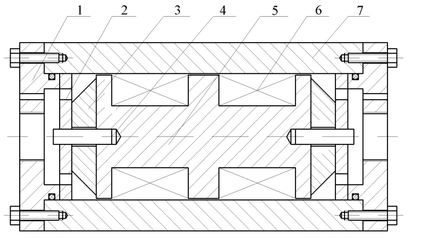
Fig.1 Schematic of the double coil MR valve

Fig.2 Principle of pressure regulating of the MR valve
The principle of pressure regulating of the double coil MR valve is shown in Fig.2.When the cur-rentI1andI2was input to the two exciting coils,the closed loop of the magnetic circuits would be formed among the valve spool,the valve body and the resistance gap,and the magnetic field will be generated in the three resistance gaps.The intensity of the magnetic fields can be adjusted by controlling the currentI1andI2.At the same time,the pressure drop between the resistance gaps can be controlled too.
3.Magnetic circuit of the double coil MR valve
When the current directions of the two exciting coils are reverse,the pressure drop is bigger than the pressure drop when the current directions are the same and the magnetic circuit of the double coil MR valve is shown in Fig.3.Because the structure of the double coil MR valve are distributed symmetrically,andL3equals 2L1,the effects of the two exciting coils are only considered as one coil.As the iron permeability is higher than the air,the flux leakage can be ignored.The magnetic resistances of each segment are as follows.

Fig.3 Magnetic circuit of the double coil MR valve
The magnetic resistance ofcentralaxis segment is

the magnetic resistance of flank is defined as

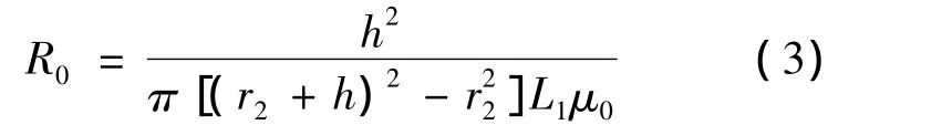
the magnetic resistance of resistance gap is
and the magnetic resistance of valve body is
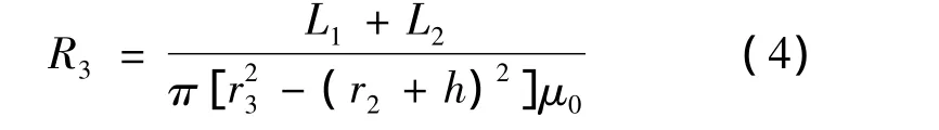
where the constant μ0is the vacuum permeability,and μ is the permeability of the material of the valve spool and the valve body.
The total magnetic resistance is given by

According to the Ohm’s law for magnetic circuit,the magnetomotive force is represented as

whereB0is the magnetic flux density of resistance gap,andS0is the flux area of resistance gap.
4.Simulation analysis using Finite Element Method(FEM)
Fig.4 shows the axisymmetric two-dimensional finite element model of the double coil MR valve.The materials of the valve spool and valve body are both 10 steel,its permeability is defined by the B-H curve of 10 steel;the material of exciting coil is copper,its relative permeability is 1;the resistance gap is full of MR fluid,its permeability is defined by the B-H curve of MRF-132DG.The value of the current density in two exciting coils is equal,and is set as 8 A/mm2.

Fig.4 Two-dimensional finite element model
The electromagnetic simulation result is shown in Fig.5 and Fig.6.From the simulation result,when the current directions of the two exciting coils are reverse,the resistance gap is divided into three effective parts by magnetic field,and the magnetic flux density of three effective parts is approximately equal.If the two exciting coils have the same current direction,the magnetic flux density in the middle part will be zero.

Fig.5 Magnetic flux of the double coil MR valve
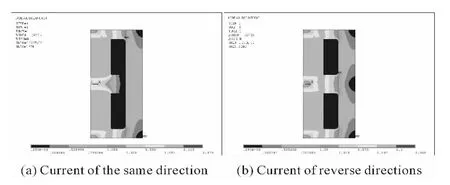
Fig.6 Magnetic density contour of the double coil MR valve
Fig.7 and Fig.8 show the magnetic flux density in different value and direction of the current of two exciting coils.When the value and direction of current are different,the magnetic flux density of middle part is approximately the average of the both ends,and the magnetic flux density of the side that close to the high-current coil is the bigger.If the value of current is different and the direction is same,the distribution of magnetic flux density in middle part is uneven.

Fig.7 Magnetic flux density under the reverse direction
input current with different input values In order to improve the quality of magnetic circuit of MR valve,the influences of bobbin diameter,active core length and resistance gap thickness on magnetic flux density were considered,as shown in Fig.9,Fig.10 and Fig.11,respectively.Fig.9 shows the magnetic flux density of resistance gap in different bobbin diameterr1.While the bobbin diameter is less than a certain value,the magnetic flux density of the resistance gap increases with the increase of the bobbin diameter.However,when the bobbin diameter is greater than a certain value,the magnetic flux density is decreased with the increase of the bobbin diameter.The reason is that the magnetic flux density of the central axis segment becomes saturated when the bobbin diameter is lesser,and it is the main factor to limit the magnetic flux density.While bobbin diameter is greater than a certain value,it becomes the main factors to influence the magnetic flux density due to the reduction of the coil turns causing magneto motive force to reduce.

Fig.8 Magnetic flux density under the same direction input current with different input values

Fig.9 Magnetic flux density of resistance gap in different bobbin diameter
Fig.10 shows the magnetic flux density of the resistance gap in different active core lengthL1.The magnetic resistance of the gap becomes larger with the increase of the active core length.At the same time,the reduction of the turns of the exciting coils makes the magneto motive force decrease,and it will make the magnetic flux density in resistance gap decrease.
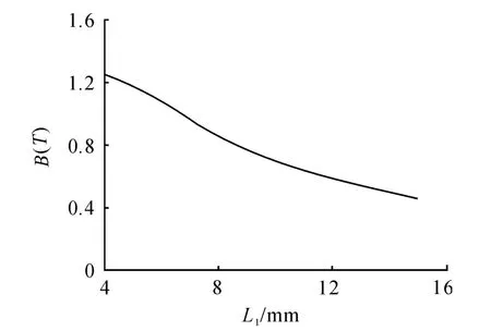
Fig.10 Magnetic flux density of resistance gap in different active core length
Fig.11 shows the influence of resistance gap thicknessh1on magnetic flux density.With the increase of the thickness of the resistance gap,the magnetic resistance of the gap increases,and the magnetic flux density decreases.
5.Modeling and performance analysis of the pressure drop of the double coil MR valve
5.1.Mathematic modeling
In the absence of magnetic field,MR fluid behaves like Newtonian fluids.Hence,in the presence of magnetic,the MR fluid follows Bingham’s plastic of flow,having variable yield strength.In this model,the constitutive relation of MR fluid is:

where τ is the shear stresses,τy(B)is the field dependent yield stress,˙γ is the shear strain rate,and η is the dynamic viscosity with no applied magnetic field.
Fig.12(a)depicts the annular fluid flow resistance channel between the inner face of the valve body and the outer annular face of the valve spool with a radius ofR.In general,the annular fluid flow resistance channel of the valve containing the MR fluid is modeled as an approximate flat parallel plate model containing the MR fluid.As shown in Fig.12(b),the width of the equivalent rectangular duct is 2πR,and R equalsr2+0.5h;the lengthLof the equivalent rectangular duct equals 2L1+2L2+L3;and the thicknesshof the equivalent rectangular duct is the thickness of the annular flow resistance gap.

Fig.12 Modeling of the MR fluid flow in an annular flow resistance channel
According to the constitutive equation of MR fluid,the pressure drop of the valve is calculated by

where△Pτand △Pηare the field-dependent and the viscous pressure drop of the double coils MR valve,respectively.
The viscous pressure drop△Pηcan be calculated as shown in Fig.13,which depicted the force condition of infinitesimal element in resistance gap.
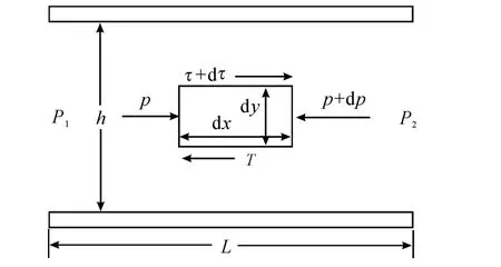
Fig.13 The force condition of infinitesimal element in resistance gap
The force balance equation of infinitesimal element is

The kinematic viscosity of the fluid is
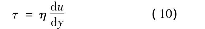
whereuis the fluid velocity.
From Eq.9 and Eq.10,one obtains that the fluid velocity u satisfies

where dp/dxis the constant pressure gradient along the flow direction,and its value is the same as the Δpη/L;c1andc2are depended on the boundary conditions.Thus the boundary conditions for the flat parallel plate flow region are?

So that

The flow rate is computed as

From Eq.13 and Eq.14,one obtains that the viscous pressure drop△Pηsatisfies

In the other hand,τηεφιελδ- δεπευδευτ is given by
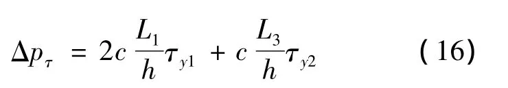
where τy1and τy2are the yield stresses of the MR fluid in the end ducts and the middle duct,respectively;cis a coefficient which depends on the flow velocity profile and has a value ranging from a minimum value of 2.0 to a maximum value of 3.0.
From Eq.8,Eq.15 and Eq.16,the pressure drop of the valve is expressed as

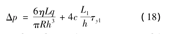
While the pressure drop is the biggest,the current directions of the two exciting coils are reverse and the current values are the maximum allowed value.In the condition of above,τy1and τy2are approximately equal and the pressure drop of the valve can be defined as
To evaluate the valve performance,an amplifying factor β is introduced and defined as the ratio of the field-dependent pressure drop to viscous pressure drop:

In order to improve the amplifying factor β,according to Eq.19,the value ofL1,handRshould be as large as possible.However,with the increase of theL1,handR,the magnetic flux density of resistance gap decreases,the yield stresses of the MR fluid reduces and the valve performance degrade.Therefore,the value ofL1,handRshould be appropriate to guarantee the valve performance.
5.2.Simulation results
The relationship between the pressure drop and the flow rate is shown in Fig.14.The pressure drop increases linearly with the increase of the flow rate when the resistance gap thickness is 0.5 mm.

Fig.14 The pressure drop in different flow rate
When analyzing the relationship between the pressure drop and the resistance gap thickness,it is assumed that the magnetic flux density of the resistance gap does not vary with the change of the resistance gap thickness.Fig.15 shows the relationship between the pressure drop and the resistance gap thickness when the flow rate is 4 L/min.The pressure drop decrease with the increase of the resistance gap thickness.
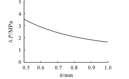
Fig.15 The pressure drop in different resistance gap thickness
When analyzing the relationship between the pressure drop and the average radius of the resistance gap,it is assumed that the magnetic flux density of the resistance gap does not vary with the change of the average radius of the resistance gap.Fig.16 shows the relationship between the pressure drop and the average radius of the resistance gap when the flow rate is 4 L/min,and the resistance gap thickness is 0.5 mm.Observing Fig.16,the pressure drop de-creases with the increase of the average radius of the resistance gap.

Fig.16 The pressure drop in different average radius of the resistance gap
6.Conclusions
In this work,the new proposed double coil MR valve provided a better performance through the finite element analysis and numerical simulations.The relationships of the bobbin diameter,active core length and thickness of resistance gap on the magnetic flux density were obtained.At the same time,the influences of the structure parameters of the double coil MR valve on the pressure drop were also reached.The new valve design has improved the efficiency of double coil MR valve significantly.
[1]Mihajlov M,Nikolic V,Antic D.Position control of an electro-hydraulic servo system[J].Mechanical Engineering,2002,1(9):1217-1230.
[2]Jolly M R,Bender J W,Carlson J D.Properties and applications of commercial MR?uids[J].Journal of Intelligent Material Systems and Structures,1999,10(13):5-13.
[3]Yokota S,Yoshida K,Kondoh Y.A pressure control valve using MR fluid[C]//Proc.Fourth JHPS-ISTP.Tokyo:[s.n.],1999:377-380.
[4]Grunwald A,Olabi A G.Design of magneto-rheological(MR)valve[J].Sensors and Actuators A,2008,148:211-223.
[5]Gorodkin S,Lukianovich A L.Magnetorheological throttle valve in passive damping systems[J].Journal of Intelligent Material Systems and Structures,1998,9(8):637-641.
[6]Nosse D T,Dapino M J.Magnetorheological valve for hybrid electrohydrostatic actuation[J].Journal of Intelligent Material Systems and Structures,2007,18(11):1121-1136.
[7]Wu R,Lin W X,Tang W.The design and analyses of magnetorheological fluid throttle valve[C]//2010 International Conference on Electrical Engineering and Automatic Control.2010:186-190.
[8]Leicht Z,Urreta H,Sanchez A,et al.Theoretical and experimental analysis of MR valve[J].Journal of Physics:Conference Series,2009,149(1):1-4.
[9]Wu R,Lin W X,Tang W,et al.The simulation analysis on performance of magnetorheological fluid throttle valve[C]//2011 International Conference on Remote Sensing,Environment and Transportation Engineering(RSETE).Nanjing:[s.n.],2011:6529-6532.
[10]Kuzhir P,Bossis G.Optimization of magnetorheological fluid valves[J].International Journal of Modern Physics B,2005,19(7-9):1229-1235.
[11]Zhu X C,Jing X J,Cheng L.Optimal design of control valves in magnetorheological fluid dampers using a nondimensional analytical method[J].Journal of Intelligent Material Systems and Structures,2012,24(1):108-129.
[12]Zhu X C,Jing X J,Cheng L.Magnetorheological fluid dampers:A review on structure design and analysis[J].Journal of Intelligent Material Systems and Structures,2012,23(8):839-873.
[13]Mansour H,Arzanpour S,Golnaraghi F.Design of a solenoid valve based active engine mount[J].Journal of Vibration and Control,2011,18(8):1221-1232.
[14]Lee U,Kim D,Hur N,et al.Design analysis and experimental evaluation of an MR fluid clutch[J].Journal of Intelligent Material Systems and Structures,1999,10(9):701-707.
[15]Kostamo E,Kostamo J,Kajaste J,et al.Magnetorheological valve in servo applications[J].Journal of Intelligent Material Systems and Structures,2012,23(9):1001-1010.
[16]Tian L,Wang Y Y.Study on power transmission technology based on MRF[J].International Journal of Modern Physics B,2005,19(7-9):1563-1569.
[17]Yoshida1 K,Soga T,Kawachi M,et al.Magnetorheological valve-integrated cylinder and its application[J].Systems and Control Engineering,2009(9):31-41.
[18]Rosenfeld N C,Wereley N M.Volume-constrained optimization of magnetorheological and electro-rheological valves and dampers[J].Smart Materials and Structures,2004,13(6):1303-1313.
[19]Nguyen Q H,Han Y M,Choi S B,et al.Geometry optimization of MR valves constrained in a specific volume using the finite element method[J].Smart Materials and Structures,2007,16(6):2242-2252.
[20]Nguyen Q H,Choi S B,Wereley N M.Optimal design of magnetorheological valves via a finite element method considering control energy and a time constant[J].Smart Materials and Structures,2008,17(2):1-12.
[21]Nguyen Q H,Choi S B,Lee Y S,et al.An analytical method for optimal design of MR valve structures[J].Smart Materials and Structures,2009,18(9):1088-1100.
[22]Li W H,Du H,Guo N Q.Finite element analysis and simulation evaluation of a magnetorheological valve[J].The International Journal of Advanced Manufacturing Technology,2003,21(6):438-445.
[23]Salloom M Y,Samad Z.Finite element modeling and simulation of proposed design magneto-rheological valve[J].The International Journal of Advanced Manufacturing Technology,2011,54(5-8):421-429.
[24]Salloom M Y,Samad Z.Magneto-rheological directional control valve[J].The International Journal of Advanced Manufacturing Technology,2012,58(1-4):279-292.
[25]Salloom M Y,Samad Z.Design and modeling magneto rheological directional control valve[J].Journal of Intelligent Material Systems and Structures,2012,23(2):155-167.
[26]Yoo J H,Wereley N M.Design of a high efficiency magnetorheological valve[J].Journal of Intelligent Material Systems and Structures,2002,13(10):679-685.
[27]Yoo J H,Wereley N M.Performance of a Magnetorheological Hydraulic Power Actuation System[J].Journal of Intelligent Material Systems and Structures.2004,15(11):847-858.
[28]Yoo J H,Sirohi J,Wereley N M.A magnetorheological piezohydraulic actuator[J].Journal of Intelligent Material Systems and Structures,2005,16(11/12):945-953.
[29]Hu W,Cook E,Wereley N M.Energy absorber using a magnetorheological bypass valve filled with ferromagnetic beads[J].IEEE Transactions on Magnetics,2007,43(6):2695-2697.
[30]Hu W,Robinson R,Wereley N M.A design strategy for magnetorheological dampers using porous valves[J].Journal of Physics:Conference Series,2009,149(1):1-4.
[31]Cook E,Hu W,Wereley N M.Magnetorheological bypass damper exploiting flow through a porous channel[J].Journal of Intelligent Material Systems and Structures,2007,18(12):1227-1232.
[32]Miao M,Hu W,Choi Y T,et al.A magnetorheological damper with bifold valves for shock and vibration mitigation[J].Journal of Intelligent Material Systems and Structures,2007,18(12):1197-1203.
[33]Robinson R,Hu W,Wereley N M.Linking Porosity and Tortuosity to the Performance of a Magneto-Rheological Damper Employing a Valve Filled With Porous Media[J].IEEE Transactions on Magnetics,2010,46(6):2156-2159.
[34]Gordaninejad F,Wang X,Hitchcock G,et al.Modular high-force seismic magneto-rheological fluid damper[J].Journal of Structural Engineering,2010(2):135-143.
[35]Aydar G,Wang X J,Gordaninejad F.A novel two way controllable magnetorheological fluid damper[J].Smart Materials and Structures,2011,19(6):18-24.
[36]Sahin H,Gordaninejad F,Wang X J,et al.Response time of magnetorheological fluids and magneto-rheological valves under various flow conditions[J].Journal of Intelligent Material Systems and Structures,2012,23(9):949-957.
[37]Ai H X,Wang D H,Liao W H.Design and modeling of a magnetorheological valve with both annular and radial flow paths[J].Journal of Intelligent Material Systems and Structures,2006,17(4):328-334.
[38]Wang D H,Ai H X,Liao W H.A magnetorheological valve with both annular and radial fluid flow resistance gaps[J].Smart Materials and Structures,2009,18(11):1-16.

- 机床与液压的其它文章
- Selection of Working Parameter for Bladder-type Accumulators with Different Conditions
- Development of Vibration Signal Acquisition and Analysis System for Machine Tools Based on LabVIEW
- Strength Analysis and Optimization of a Torsion Beam Rear Suspension
- Analysis of the Optimization of Gear Pump Pulsation Based on Matlab
- Remote Condition-based Maintenance Approach to Hydraulic System of Construction Machinery
- The Conception and Kinematic Simulation of a Cam Mechanism Continuously Variable Transmission