
Strength Analysis and Optimization of a Torsion Beam Rear Suspension
2013-06-02 06:16CHENSongLEIGngLIUYing
机床与液压 2013年18期
CHEN Song ,LEI Gng,LIU Ying
a.College of Mechanical Engineering;b.Key Laboratory of Manufacture and Test Techniques for Automobile Parts,Ministry of Education,Chongqing University of Technology,Chongqing,400054,China
As the production capacity demand of the automobile market keeps expanding with the development of social economy and meanwhile people’s requirements on automobile performance are increasingly higher,automobile manufacturers are required to constantly improve the performance of automobiles and components while enhancing production capacity.Suspension system,as a key component of automobile chassis,has major effect on the driving safety and reliability and practical performance of automobiles and is also a hot issue in current automobile design and research.In practical application,destruction of torsion beam rear suspensions is caused by fatigue in most cases[1].
This paper calculates the strength of the torsion beam rear suspension with finite element method and accordingly performs structural optimization to the suspension.The modified structure is simulated and analyzed,and the comparison between the simulation results before and after the modification shows that after modification,the stress of the structure is effectively reduced and the strength of the suspension is significantly increased,so that the destruction of the suspension due to fatigue under steering and ultimate torsion can be prevented.
1.Force Analysis of Torsion Beam Suspension
Strength analysis of torsion beam suspension is generally under 4 operating conditions,namely ultimate left steering,impact,braking and ultimate torsion(simulation bench test)[2].In this paper,direction is indicated with vehicle coordinate system[3].Force analysis of the suspension is performed under the 4 operating conditions hereunder.
1.1.Left steering condition
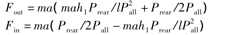
In combination of the roll-steering effect caused by steering acceleration,load of the rear-wheel center is calculated as below:
Steering force
Wheel center torque
Mout=Fout·R
Min=Fin·R
Supporting force
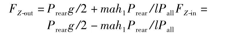
Wheremrefers to the mass of the entire vehicle with full load,arefers to steering or braking acceleration,h1refers to the height of mass center of the entire vehicle with full load,lrefers to the rear wheel tread,nrefers to wheel base,Prearrefers to full load of rear axle,Pallrefers to full load of the entire vehicle,andRrefers to tire radius.
Based on the characteristics of steering condition,in the establishment of the finite element model,all freedom of motion of the springs at both ends is restricted and corresponding load is applied at the center of the brake mounting plates at both ends of the suspension.
1.2.Braking condition
In combination of the fore-rake effect caused by braking acceleration,load of the rear-wheel center is calculated as below:
Braking force
Frear=ma(Prear/2Pall-mah1/2Pall)
Braking torque
Mrear=Frear·R
Supporting force
FZ=Prearg/2-mah1/2n
Where mrefers to the mass of the entire vehicle with full load,arefers to steering or braking acceleration,h1refers to the height of mass center of the entire vehicle with full load,lrefers to the rear wheel tread,nrefers to wheel base,Prearrefers to full load of rear axle,Pallrefers to full load of the entire vehicle,andRrefers to tire radius.
Based on the characteristics of braking condition,all freedom of motion of the springs at both ends is restricted in the finite element model and corresponding load is applied at the center of the brake mounting plates.
1.3.Impact condition
Wheel center load of the fore steering knuckle is calculated as below:
Impact force
F=2.5gPrear/2
Under impact condition,the spring of the suspension is compressed to extreme position due to high impact acceleration and then the damper acts.Therefore,rear-wheel center is swayed up to extreme position through forced displacement to achieve displacement constraint,a force of 5 201 N is respectively applied at the mounting positions of the springs of the suspension,and impact force is applied at the center of the brake mounting plates.
1.4.Ultimate torsion condition
Simulation is performed based on the operating condition of the ultimate torsion bench test provided by the manufacturer.All freedom of motion of the springs at both ends is restricted,and forced displacements of 70 mm and-70 mm are added respectively inZdirection of the brake mounting plates at both ends of the suspension to simulate the strength of the torsion beam rear suspension under ultimate torsion condition.
A specific product of a certain enterprise in Chongqing:the mass of the entire vehicle with full load is 1 690 kg,accelerations of steering,braking and impact are 0.8 g,0.8g and 2.5 g respectively,the height of mass center of the entire vehicle with full load is 504 mm,the rear wheel tread is 1 520 mm(empty);the wheel base is 2 700 r/min(empty),the full load of rear axle is 787 N,the full load of the entire vehicle is 1 690 N and the tire radius is 316 mm.Loads of the torsion beam rear suspension under each operating condition are calculated with the parameters above and the results are listed below.Fout=47 217 N,Fin=1 448.4 N,Mout=1 492.1 N·m,Min=457.7 N·m,FZ-out=5 902.5 N,FZ-in=1810.1 N,Frear=2 095.7 N,Mrear=662.2 N·m,FZ=2 619.7 N andF=9 640.75 N.
2.Establishment of Analysis Model
2.1.Rubber bushing simulation method
In order to reduce amount of calculation while fully reflecting the actual situation of the original model,equivalent treatment is performed in this paper with single-point spring,spring and other items for some connection elements(e.g.rubber bushing and stabilizer bar).This paper uses spring element to equivalently replace rubber bushing[4],for repeated experiments have proved that spring element can simulate the stiffness of rubber bushing in axial and radial directions.
In the use of spring element to simulate rubber bushing and in accordance with the features of the rubber bushing,3 spring elements are set up on the bushing seat on one side to simulate the stiffness of rubber bushing in 3 directions.Stiffness values for 3 levels of motion freedom of the spring element are shown in Tab.1.Corresponding single-point spring is set up on the other side of the suspension with the same method.

Tab.1 Stiffness Values for 3 Levels of Motion Freedom of Spring Element
2.2.Establishment of finite element model
Finite element discretization is first performed before finite element analysis,namely meshing to a make the structure a discrete entity.In this paper,geometric model of the torsion beam rear suspension is imported into the finite element pre-processing software HyperMesh to establish the finite element model.The torsion beam rear suspension is made of QSTE420TM cold-formed hot-rolled automobile structural steel plate.See Tab.2 for characteristic parameters of the material.
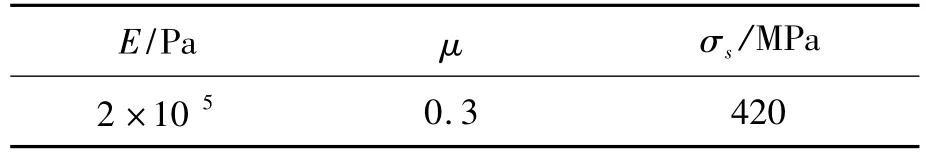
Tab.2 Material Characteristics of Torsion Beam Rear Suspension
Fig.1 shows the finite element model of the torsion beam rear suspension established in the finite element pre-processing software HyperMesh.The element target size of the model is 5 mm,the total number of modes is 34 520 and the total number of elements is 33 602 928 being triangle elements and the rest being quadrilateral meshes.In order to describe welding spots more graphically,six-node entity mesh is adopted for simulation in the welding seam[5].
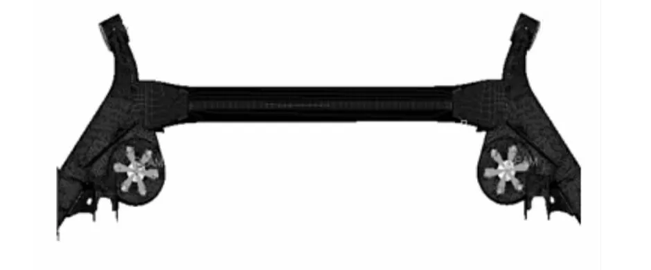
Fig.1 Finite Element Model of Torsion Beam Rear Suspension
Independent nodes are established respectively at the centers of suspension spring seat,bushing and brake mounting plate,stiff connection element RBE2 is established with the node as the center,and 3 spring elements are established at the suspension spring seat.Based on the requirements of actual operating condition,spring length and stiffness are set at 206 mm and 27.3 N/mm respectively.
3.Strength Analysis
Results of the strength analysis of the suspension based on the said 4 operating conditions are shown in Fig.2.It can be seen from the stress cloud chart of Fig.2 that the maximum stress under braking condition occurs at the spring seat and is 204 MPa and the maximum stress under impact condition occurs at the joint between the spring seat and the suspension transom and is 289 MPa(see Tab.3),and the material of the spring seat is SAPH440m,with a yield strength of 305 MPa.The stress under either operating condition is lower than the yield strength of the material and thus will not cause damage under the actual operating condition of the suspension.
Under left steering condition,as shown in Fig.2(a),the stresses at the inner gusset plate of the suspension transom and at suspension beam end are relatively high,with a maximum value of 483 MPa.Under ultimate torsion condition,as shown in Fig.2(b),the maximum stress occurs at the beam end,which is not in accordance with actual application,and the value of maximum stress is 515 MPa.The transom is made of QSTE420TM cold-formed hotrolled automobile structural steel plate,whose yield limit is 420 MPa.The maximum stresses under left steering and ultimate torsion conditions are both higher than the yield limit of 420 MPa of the material,and thus the suspension will be broken due to high stress[6].The structure of the rear suspension shall be modified to reduce stress and enhance the strength of the suspension.
4.Structural Optimization
When the suspension structure is under steering or ultimate torsion condition,stress at the part around the inner gusset plate is relatively high,and thus consideration shall be first given to the structural optimization of the inner gusset plate.The manufacturer requires that the structure shall not be subject to major modification for the convenience of production and assembly and that the stresses under steering and ultimate torsion conditions shall be significantly reduced.In the current scheme,local modification is performed on the basis of original suspension structure,namely only cutting a U-groove to the inner gusset plate without modifying the rest part of the structure.Finite element mesh of the modified model is generated and analysis and calculation are performed in accordance with the said operating conditions.Comparison between the pre-and post-modification models is shown in Fig.3.The stress cloud chart of the optimized structure is shown in Fig.4.

Fig.2 Stress Cloud Chart of Unmodified Structure
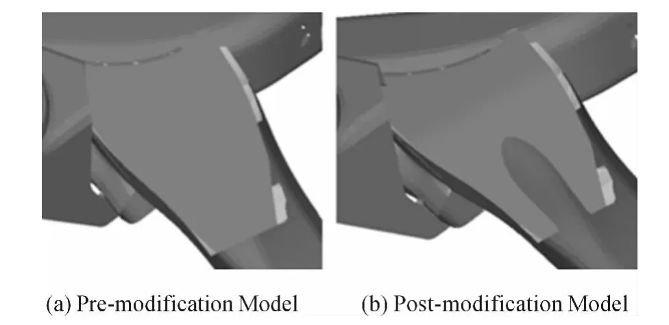
Fig.3 Comparison between Pre-and Post-modification Models
It can be known from the stress analysis that the maximum stresses for braking and impact conditions are 203 MPa(see Tab.3)and 280 MPa respectively.The maximum stresses under these 2 operating conditions are slightly lower after structural optimization and the positions where the maximum stresses occur are not changed,and hence the suspension will not be damaged.After structural optimization,the maximum stress under steering condition(see Fig.4)occurs at the beam end and the transom,and the value is 385 MPa;the maximum stress under ultimate torsion condition occurs at the suspension transom and is 381 MPa and evenly distributed.
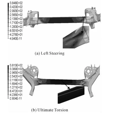
Fig.4 Stress Cloud Chart of Modified Structure
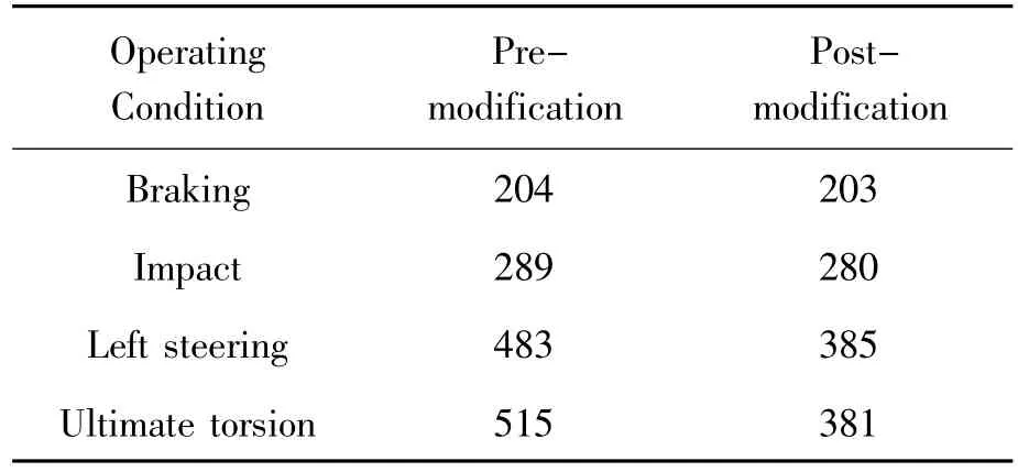
Tab.3 Comparison between Pre-and Post-Modification Stresses under Each Operating Condition MPa
The stresses under these 2 operating conditions are both lower than the yield limit of 420 MPa of the suspension transom material and are in accordance with the stress distribution of the suspension in actual application,and meanwhile the stresses under braking and impact conditions are slightly lower.The stress of the torsion beam rear suspension is lower after structural optimization and the modified suspension meets requirements of strength and application.
In this optimization scheme,a U-groove is cut in the inner gusset plate to reduce maximum stress and improve structural strength while the rest part of the structure is not modified.Meanwhile,relatively small structural modification facilitates the manufacturer’s mass production of the suspension.The expected goal is reached and the modified structure has been applied in the enterprise.
5.Conclusions
1)For the original design,the suspension will not be damaged under braking and impact conditions,but under steering and ultimate torsion conditions,stresses at the inner gusset plate and the transom connecting to the inner gusset plate are relatively high and therefor result in a strengthen problem.
2)Based on analysis results,this paper proposes a structural modification scheme,and the comparison between pre-and post-modification stresses and stress distributions indicates that the maximum stress of the optimized structure is significantly lower.
3)Stress of the structure is significantly reduced after modification according to the analysis herein,but besides stress and stress distribution,the fatigue breakdown of components also has a strong relationship with material fatigue characteristics and cyclical load of the component,and thus change of the fatigue characteristics of the rear suspension requires further study.
[1]WANG Xi-bing,CHANG Jia-mao.Design and Simulation Calculation of Twist Beam Suspension of Car[J].Agri-cultural Equipment& Vehicle Engineering,2008(7):29-31.
[2]PAN Ping,WANG Guo-quan,LIN Mei-you,et al.Strenghth analysis of a semi-trailing tractor frame[J].Journal of Beijing Information Science & Technology University,2010,25(2):52-57.
[3]YU Zhi-sheng.Cars theory[M].Beijing:China Machine Press,2009.
[4]YU Zhen-long,YI Long-xi.Analysis of Structural Characteristics of Rubber Bushing in Car Suspension[J].Automobile Technology,2009(8):34-38.
[5]YU Kai-ping,ZHOU Chuan-yue.From Entry to the Master of HyperMesh[M].Beijing:Science Press,2005.
[6]YU Jian,ZUO Shu-guang,CHEN Dong-hua,et al.Modeling and Dynamic Character Analyzing of Twist Beam Rear Suspension on ADAMS[J].Journal of System Simulation,2006(8):2300-2303.
[7]CHEN Bao,LI Can,LIU Sheng-kun,et al.Research for Structure Optimization about Flex Torsion Beam of Rear Suspension with RubberBushings[J]. Journalof Chongqing University of Technology:Natural Science,2012(2):6-10.
[8]ZHANG Ying-feng,MA Biao,FANG Jing,et al.Fault diagnosis of power-shift steering transmission based on multiple outputs least squares support vector regression[J].Journal of Beijing Institute of Technology,2011(2):99-204.
[9]ZHANG Jin-le,MA Biao,ZHANG Ying-feng,et al.Simulation study on starting of dual clutch transmission for tracked vehicles[J].Journal of Beijing Institute of Technology,2011(1):77-83.

- 机床与液压的其它文章
- Selection of Working Parameter for Bladder-type Accumulators with Different Conditions
- Development of Vibration Signal Acquisition and Analysis System for Machine Tools Based on LabVIEW
- Numerical Analysis and Experimental Research on Micro Milling Process with Cycloidal Tool Path
- Analysis of the Optimization of Gear Pump Pulsation Based on Matlab
- Simulation Evaluation and Performance Analysis of a Double Coil Magnetorheological Valve
- Remote Condition-based Maintenance Approach to Hydraulic System of Construction Machinery