开放式的高分辨率超声成像系统
2013-11-23 06:39邱维宝于妍妍黎国锋郑海荣
集成技术 2013年5期
邱维宝 于妍妍 黎国锋 钱 明 孙 雷 郑海荣*
1(中国科学院深圳先进技术研究院生物医学与健康工程研究所 深圳 518055)
2(香港理工大学物医学工程跨领域学部 香港 )
1 Introduction
High-resolution, noninvasive visualization of living tissues is an indispensable technique to observe physiological activities on a miniature scale. Diseases associated with small human structures such as eye, skin,blood vessel can benef i t from this technique. In addition,this technique can also facilitate preclinical researches of small animal models of human diseases in mice,rats, zebrafish, etc. Preclinical studies of small animal models can improve the knowledge and understanding of physiological and functional mechanism of pathologies and treatment strategies. Current high-resolution imaging modalities include micro-CT (computed tomography)[1],micro-MRI (magnetic resonance imaging)[2], micro-PET (positron emission tomography)[3], optical coherent tomography (OCT)[4], and high-resolution ultrasound imaging[5-6].
High-resolution ultrasound imaging, also known as micro-ultrasound (micro-US)or ultrasound biomicroscope(UBM), has made it possible to delineate small structures with fine spatial resolution on the order of tens of microns[7]. It is clinically used for ophthalmology[8],dermatology[9], and intravascular diseases[10]. Preclinical small animal model research has also been signif i cantly propelled by this technique, for example, malignant tumor diagnosis[11-12], cardiac diseases[13-14], and embryonic developmental biology[15-16]. Recently, it has been combined with optical method such as OCT or fluorescence spectroscopy as a dual-modality imaging technique and demonstrated great potentials in biomedical studies[17-19]. Other advanced imaging techniques also take the advantage of high-resolution ultrasound imaging and extend its biomedical investigations such as photoacoustic imaging[20-21], contrast enhanced imaging[22], modulated excitation imaging[23], 3D imaging[24], elastography imaging[10,25], and harmonic imaging[26]. Each study is unique in nature and requires different utilization of the ultrasound imaging system. Imaging systems(eg:vevo 770, vevo 2100, Visualsonics, Inc., Canada)with fixed specifications, such as transducer characteristics,data acquisition strategy, signal processing method,and image display approach, do not satisfy extensive preclinical study requirements. Researchers need a highly flexible device to best suit their specific investigations.In addition, access to the raw experimental data is also important to scientific discovery. Therefore, an open and flexible ultrasound imaging system allowing users/researchers to customize for individual biomedical study is necessary.
In this paper, the development of an open imaging system with high flexibility and compactness was described to satisfy various biomedical investigations.This open system incorporated a high-voltage arbitrary waveform generator, a programmable imaging receiver,high-precision servo motors, and high-performance transducers. FPGA was served as the core processor and replaced hardware circuitry for fast processing speed and programmability. Moreover, low-noise and high-speed analog electronics was used to achieve high signal-tonoise ratio (SNR)and high sensitivity. A PCIE bus, as a high-speed data transmission interface, was incorporated in this platform for image data or RF raw data transfer to a computer through direct memory access (DMA)operation. Nevertheless, all the electronics such as amplifier, filter, analog-to-digital converter (ADC)and FPGA were incorporated in a single PCB for compactness and cost-effectiveness. It was demonstrated that B-mode imaging, Doppler imaging, modulated excitation imaging,and intravascular imaging were realized in this system.
2 System Description
The designed open system included a high-frequency pulse generator, a high-speed ultrasound imaging receiver with analog front-end electronics and digital back-end unit, and a high-speed mechanical scan probe. The block diagram is shown in Fig.1. The pulse generator employed FPGA and high-speed metal-oxide-semiconductor field effect transistors (MOSFETs)to achieve high-voltage pulse generation. A high-speed imaging receiver was developed including front-end electronics, ADC, FPGA,and high-speed computer interfaces, which allowed to process the images in real-time with high programmability and flexibility. A personal computer was employed for image display and data storage for further investigations.Graphical user interface software was programmed in Visual C++ to process real-time ultrasound images. A PCIE bus utilization supports high-speed data transfer and real-time imaging.
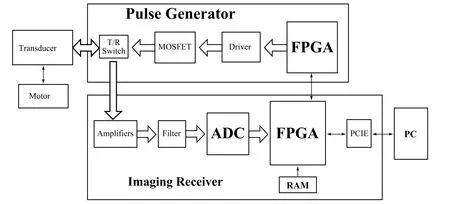
Figure 1. The block diagram of the high-resolution open system
2.1 Pulse Generator
The designed pulse generator for this open system incorporated a bipolar pulse generation scheme and an arbitrary waveform generator. A programmable FPGA component (Cyclone III, EP3C16F484C6N, Altera Corporation, San Jose, CA)was employed to control the timing and spectrum characteristics of the high voltage short pulse. Therefore, the pulse generator could be easily adjusted to support transducers with different center frequencies as well as match with the spectrum of individual transducer to acquire the optimized performance. Two MOSFET drivers (EL7158, Intersil Corporation, Milpitas, CA)were employed to accomplish the voltage level shift and high current output to excite the high-speed MOSFET pair (TC6320, Supertex Inc.,Sunnyvale, CA). The MOSFET pair could offer more than 150 Vpp breakdown voltages and a 2A output peak current, which made it suitable to produce a high-voltage pulse for ultrasound imaging.
The waveform for modulated excitation imaging usually requires amplitude and frequency modulation(Chirp excitation) or phase modulation (Barker excitation and Golay excitation) of sinusoidal carrier signal. A programmable high-voltage arbitrary waveform generator was designed to generate various arbitrary waveforms for different modulated excitation imaging. A 16-bit DAC (DAC5682Z, Texas Instruments Inc., TX) with 1 giga-samples per second (GSPS)was employed to convert digital arbitrary waveforms to analog signals at a frequency higher than 100 MHz. Two stages of high-speed operational amplifiers (THS3091, Texas Instruments Inc., TX)were used to amplify the waveforms. Then a push-pull vertical diffused metal-oxide-semiconductor(VDMOS)transistor (SR705, Polyfet RF Devices,Camarillo, CA)was employed in the third stage for highvoltage amplif i cation.
2.2 High-speed Digital Receiver
The center frequency of high-resolution ultrasound is usually from 20 MHz to 80 MHz. So the echo receiver should have the capability to process this high-frequency ultrasound signal. In the developed open system, highprecision ultrasound signal amplif i cation and acquisition,real-time image processing, and fast data transfer were achieved in the high-speed imaging receiver. It utilized low-noise amplifiers and high-speed ADC to amplify and digitize the small ultrasound echo signal,respectively. Raw RF data which were acquired by the ADC after low-noise amplification were processed directly by the high-speed FPGA for fast imaging and compact implementation. In detail, a low-noise amplif i er(SMA231, Tyco Electronics Co., Berwyn, PA) was used as the fi rst stage amplif i er to support 27 dB gain. A lowdistortion amplifier (THS4509, Texas Instruments Inc.,Dallas, TX) was used as the second stage amplifier for further 20 dB amplification. A low-pass filter (RLP83+,Mini-Circuits, Brooklyn, NY) with a cut frequency of 93 MHz was employed for ADC anti-aliasing. A highspeed 11 bits ADC (ADS5517, Texas Instruments Inc.,Dallas, TX) with a maximum sampling rate of 200 MSPS was utilized for data converting. After the digitization,the digital signal was transferred to FPGA through the low-voltage differential signaling (LVDS)bus. A highperformance FPGA (Stratix II EP2S60F672I4, Altera Corporation, San Jose, CA)with great signal integrity was employed, which could support data processing at an adequate speed. This component included 39 DSP blocks (total 288 9×9Multipliers)which could eff i ciently implement high-speed digital signal processing algorithms. It demonstrated up to 287 MHz high order FIR, Hilbert transform and high-speed DSC algorithms.It could also support DDR2 SDRAM and PCI interface.A 512M bits RAM combined with two DDR2 SDRAM(MT47H16M16, Micron Technology Inc., Boise, ID)was used for temporary buffering of data. Various programmable algorithms could be achieved in the FPGA including band pass filter, compression filter, envelope detector, and digital scan converter for modulated excitation imaging. The receiver also supported raw RF data acquisition. Both processed image data and raw RF data could be transferred to a computer through PCIE interface (PEX8311, PLX Technology Inc, Sunnyvale,CA)for displaying or post-processing.
2.3 Imaging Algorithms
As a fi eld programmable microprocessor, the FPGA can achieve various functionalities traditionally realized by hardware circuitry. Moreover, the functions could easily be changed or modified by reprogramming the FPGA without change of hardware. Thus, the FPGA technology could significantly improve the system flexibility and diversity by programmable and reconf i gurable algorithms.Fig. 2 shows the representative structure of implemented algorithms for real-time B-mode imaging and directional PW Doppler.
For B-mode imaging, three steps were adopted for data preconditioning, i.e. in the order of execution, band pass filter (BPF), digital time gain compensation (TGC)and envelope detection. After removing noises by BPF, the data were digitally amplif i ed by conf i gurable coeff i cients to compensate for ultrasound attenuation loss in tissues called TGC. The acquired envelop data then underwent DSC and logarithmic compression. The TGC, DSC and logarithm compressor were all reconfigurable by users through GUI software. For directional PW Doppler,BPF was also employed but with different coefficients conf i guration tuned for fl ow measurement. A novel digital quadrature demodulation was used to extract the flow information from the echo signal. The data were then saved in the dual port RAM for gate selection. When a train of data was accumulated, the spectrum extraction was then launched to estimate the fl ow velocity. Finally,image data or spectrogram data were sent to a computer through PCIE bus for display and storage.
2.4 Evaluation Method
The performance of the open system electronics was tested by a 240 MHz function generator (AFG 3251,Tektronix Inc., Beaverton, OR), a digital oscilloscope(LeCroy wavepro 715Zi, LeCroy Corp., Chestnut Ridge,NY), a signal generator (HP8656B, Hewlett Packard),a spectrum analyzer (HP8591E, Hewlett Packard), and a series of attenuators (Mini-Circuits, Brooklyn, NY).The signal generator and the spectrum analyzer were employed to test the gain linearity and fl atness of analog electronics. The noise level of the system was tested by measuring the minimum detectable signal level and dynamic range. Five-cycle sinusoidal signal generated by the function generator was attenuated by a series of attenuators and then sent to the imaging receiver. After passing through the front-end electronics, the amplitude of the weak signal that could just be identif i ed from the background noise determined the minimum detectable signal level. Given the input range of the high-speed ADC(2 Vpp), the dynamic range could be derived from the gain and the minimum detectable signal level.
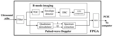
Figure 2. Schematic of algorithms implemented in the FPGA for real-time B-mode imaging and directional pulsed-wave Doppler.
A wire phantom consisting of five 20 μm diameter tungsten wires (California Fine Wire Co., CA), was used to evaluate the image resolution. A tissue mimicking phantom was fabricated to further test the image quality of the open platform. The phantom fabrication procedure followed Madsen’s method[27]. It consisted of a mixture of deionized water, high-grade agarose, preservative,propylene glycol, fi ltered bovine milk, and glass-bead to generate tissue mimicking attenuation and backscattering.Anechoic spheres were fabricated separately and dispersed in the phantom to test the system resolution.The size of the anechoic spheres was in the range of 180-280 μm controlled by a dedicated sieve (Fisherbrand sieves, Fisher Scientif i c, Pittsburgh, PA).
3 Results
The system prototype for the proposed open system was shown in Fig. 3. Fig. 3(a)showed the arbitrary waveform generator in an eight-layer PCB. Fig. 3(b)showed the programmable imaging receiver with an eight-layer PCB incorporating low-noise front-end electronics, ADC,SDRAM, high speed FPGA, and PCIE interface.
3.1 Electronics Performance
Table 1 summarized the performance of the open system electronics. The highest amplitude of bipolar pulse was 160 Vpp with adjustable center frequency and bandwidth(Fig. 4). Table 1 also demonstrates that the maximum gain of the front-end electronics is 47 dB with good linearity at a maximum fl uctuation of less than ±1.2 dB between 10 MHz and 90 MHz. The minimal detectable signal level of the system receiver is less than 25 μV. Given the input range of the high-speed ADC (2 Vpp), the system can allow a 51 dB dynamic range at 35 MHz center frequency.
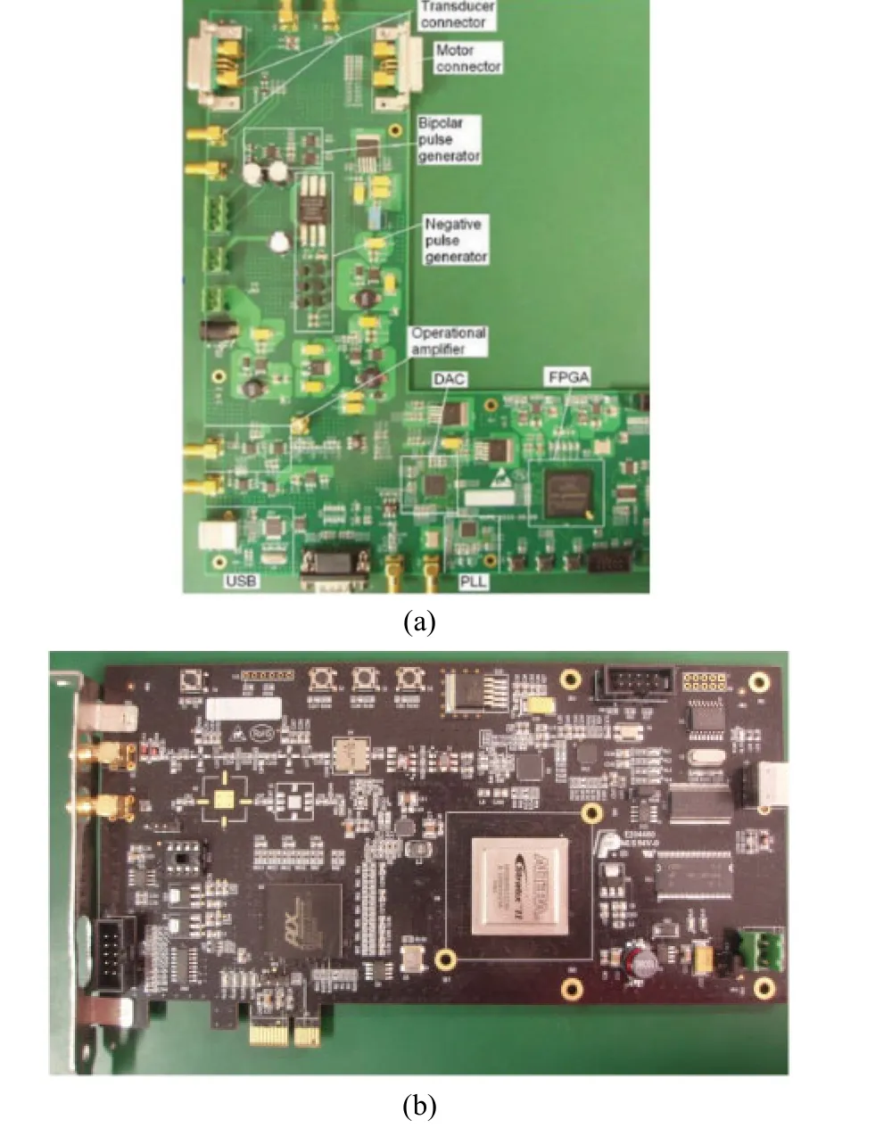
Figure 3. (a)Photographs of the designed open system including a programmable pulse generator (b)and a high-speed imaging receiver
The software-based band pass filter (BPF)was programmed in the FPGA to further remove the noise and improve the signal SNR. Quantitative analysis showed that approximately 4.8 dB SNR improvement was achieved after applying the BPF, which increased the system dynamic range to 55.8 dB. The algorithmic scheme implemented in the FPGA could achieve highspeed imaging by pipe-line signal processing. The data transferring speed was higher than 150 MByte/s for PCIE interface. At the image size of 512×512 pixels, the frame rate can be higher than 200 images per second for PCIE.Current frame rate is limited by the motor, and it can besignificantly improved if a faster motor is used. With the current utilization of FPGA resources, much more complicated signal processing may be implemented to acquire useful information than vessel morphology, such as the virtual histology (tissue characterization based on ultrasound raw RF data).
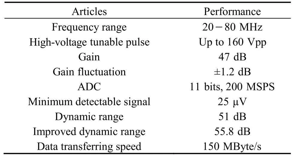
Table 1. Electronics performance of the open system
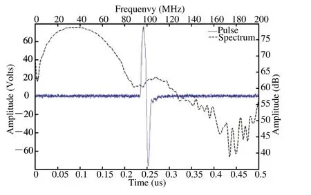
Figure 4. High-voltage bipolar monocycle pulse with 35 MHz center frequency, 150 Vpp amplitude, and 56 MHz 6dB bandwidth.
3.2 B-mode Imaging
The image quality of this system was evaluated by a customized wire phantom. The wire phantom consisted of five 20 μm diameter tungsten wires (California Fine Wire Co., CA)of which distance intervals along vertical and horizontal directions were 1.6 mm and 1.0 mm respectively. The ultrasound image of this wire phantom was shown in Fig. 5 with a dynamic range of 50 dB.In this experiment, a 35 MHz PVDF single element transducer was employed. (Characteristics: focal length 13.6 mm, bandwidth 88%, f-number 2.7). No visible noise was noticed in this image.
Fig. 6 showed the ultrasound image of the tissue phantom acquired by this system prototype. The black circular dots appearing in the images were the anechoic spheres producing no detectable echoes. The diameter of the spheres were at approximately 180 μm, correlating well with the actual sphere size. The transducer for this experiment was a 50 MHz lithium niobate (LiNbO3)transducer with focal length of 9.3 mm and bandwidth of 47%.
3.3 Flow Imaging
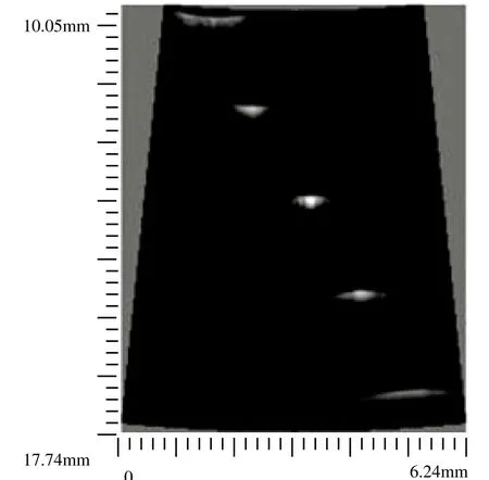
Figure 5. Wire phantom image of the open platform.

Figure 6. Image of tissue phantom with anechoic spheres. The dynamic range for this test is set at 48 dB. The trigger pulse is single cycle 150 Vpp bipolar pulse.

Figure 7. The pulsed-wave Doppler waveform of a vein in the back of a human hand.
Fig. 7 showed an in vivo spectrogram acquired from a vein in the back of a human hand. A needle transducer(42.5 MHz)was placed close to the vein coupled by ultrasound gel with an angle of 72 degrees approximately.A seven-cycle 40Vpp sinusoidal pulse was generated with PRF of 1.95 KHz. The blood moving away from the transducer confirmed the negative velocity profile. The cyclic pattern of the spectrogram correlated well to the heart beat of the subject. The heart rate was 80 beats/min measured from the spectrogram agreed with the heart rate of 78 beats/min of the subject.
3.4 Modulated Excitation Imaging
Fig. 8 showed in vivo ultrasound images of the dorsal skin of a human hand acquired by the short pulse imaging and the modulated excitation imaging with the proposed system. The dynamic range was set to 52 dB in both two images. The image of modulated excitation was brighter than the image of short pulse excitation, simply because the echo signals from the modulated excitation method was much larger. The penetration depth has been significantly improved by the chirp-based modulated excitation imaging technique. Moreover, motor noise was clearly visible in the short pulse imaging, while the noise was unnoticeable in the modulated excitation imaging.
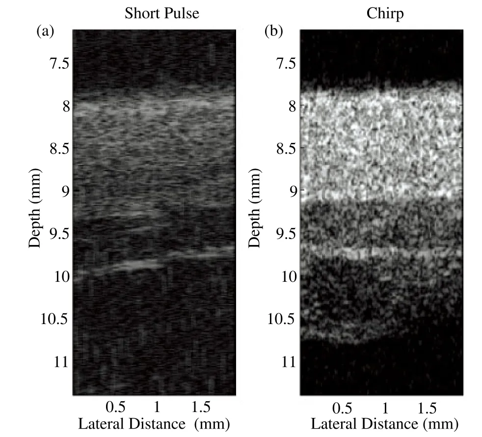
Figure 8. In vivo images of the dorsal skin of a human hand(a)The image of short pulse imaging. (b)The image of chirp-based modulated excitation imaging.
3.5 Intravascular Imaging
The designed open system supports various applications for micro-ultrasound techniques. Intravascular ultrasound imaging was also achieved by replacing the transducer with IVUS transducer. The motor was also changed with a rotary motor. In vitro coronary artery specimen was used for system evaluation. The ultrasound image of specimen was shown in Fig. 9(a). Different layers of the artery could be clearly identif i ed in the ultrasound image.The result from a multi-modality imaging combining IVUS and photoacoustics was shown in Fig. 9(b). An actively Q-switched pulsed laser (Explorer 532 Laser System, Spectra-Physics, Santa Clara, CA)operating at 532 nm wavelength generated very short laser pulses with 240 μJ energy. Ultrasound imaging was launched after the acquisition of photoacoustic signal. The echo intensity of ultrasound imaging slightly increased in bottom right corner of the tissue. This difference could be clearly visualized in photoacoustic image which indicated the change of tissue composition. Combined image showed the complementary nature of ultrasound imaging and photoacoustic imaging that could be useful for the diagnosis of intravascular diseases. This in vitro experimental result clearly demonstrated the capability and fl exibility of the proposed open system.
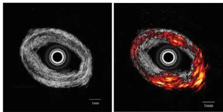
Figure 9. In vitro imaging of human coronary artery (a)IVUS image.(b)Combined image of IVUS and photoacoustics.
4 Conclusions
In this paper, a programmable open system for real-time high-resolution ultrasound was developed and evaluated based on a high-speed FPGA. It was implemented in a compact and cost-effective PCB scheme. This open system demonstrated a high image quality with a good spatial resolution for preclinical small animal imaging.The flexible and programmable design makes the open system suitable for various biomedical studies.
[1]Badea C T, Drangova M, Holdsworth D W, et al. In vivo small animal imaging using micro-CT and digital subtraction angiography [J]. Physics in Medicine and Biology, 2008, 53(19):319-350.
[2]Driehuys B, Nouls J, Badea A, et al. Small animal imaging with magnetic resonance microscopy [J]. ILAR Journal, 2008, 49(1):35-53.
[3]Schnöckel U, Hermann S, Stegger L, et al. Small-animal PET:a promising, non-invasive tool in pre-clinical research [J].European Journal of Pharmaceutics and Biopharmaceutics,2010, 74(1): 50-54.
[4]Fujimoto J G. Optical coherence tomography for ultrahigh resolution in vivo imaging [J]. Nature Biotechnology, 2003,21(11): 1361-1367.
[5]Foster F S, Zhang M Y, Zhou Y Q, et al. A new ultrasound instrument for in vivo microimaging of mice [J]. Ultrasound in Medicine and Biology, 2002, 28(9): 1165-1172.
[6]Foster F S, Mehi J, Lukacs M, et al. A new 15-50 MHz arraybased micro-ultrasound scanner for preclinical imaging [J].Ultrasound in Medicine and Biology, 2009, 35(10): 1700-1708.
[7]Foster F S, Pavlin C J, Harasiewicz K A, et al. Advances in ultrasound biomicroscopy [J]. Ultrasound in Medicine and Biology, 2000, 26(1): 1-27.
[8]Silverman R H, Ketterling J A, Coleman D J. High-frequency ultrasonic imaging of the anterior segment using an annular array transducer [J]. Ophthalmology, 2007, 114(4): 816-822.
[9]Vogt M, Ermert H. In vivo ultrasound biomicroscopy of skin:spectral system characteristics and inverse fi ltering optimization [J].IEEE Transactions on Ultrasonics, Ferroelectrics, and Frequency Control, 2007, 54(8): 1551-1559.
[10]de Korte C L, van der Steen A F, Cespedes E I, et al.Characterization of plaque components and vulnerability with intravascular ultrasound elastography [J]. Physics in Medicind and Biology, 2000, 45(6): 1465-1475.
[11]Cheung A M, Brown A S, Hastie L A, et al. Three-dimensional ultrasound biomicroscopy for xenograft growth analysis [J].Ultrasound in Medicine and Biology, 2005, 31(6): 865-870.
[12]Goessling W, North T E, Zon L I. Ultrasound biomicroscopy permits in vivo characterization of zebrafish liver tumors [J].Nature Methods, 2007, 4(7): 551-553.
[13]Zhou Y Q, Foster F S, Nieman B J, et al. Comprehensive transthoracic cardiac imaging in mice using ultrasound biomicroscopy with anatomical confirmation by magnetic resonance imaging [J]. Physiological Genomics, 2004, 18(2):232-244.
[14]Du J, Zhang C, Liu J, et al. A point mutation (R192H)in the C-terminus of human cardiac troponin I causes diastolic dysfunction in transgenic mice [J]. Archives of Biochemistry and Biophysics, 2006, 456(2): 143-150.
[15]Zhou Y Q, Foster F S, Qu D W, et al. Applications for multifrequency ultrasound biomicroscopy in mice from implantation to adulthood [J]. Physiological Genomics, 2002,10(2): 113-126.
[16]Kulandavelu S, Qu D, Sunn N, et al. Embryonic and neonatal phenotyping of genetically engineered mice [J]. ILAR Journal,2006, 47(2): 103-117.
[17]Römer T J, Brennan III J F, Puppels G J, et al. Intravascular ultrasound combined with Raman spectroscopy to localize and quantify cholesterol and calcium salts in atherosclerotic coronary arteries [J]. Arteriosclerosis, Thrombosis, and Vascular Biology, 2000, 20(2): 478-483.
[18]Sun Y, Park J, Stephens D N, et al. Development of a dual-modal tissue diagnostic system combining time-resolved fl uorescence spectroscopy and ultrasonic backscatter microscopy [J]Review of Scientif i c Instruments, 2009, 80(6): 065104.
[19]Yang H C, Yin J, Hu C, Cannata J, et al. A dual-modality probe utilizing intravascular ultrasound and optical coherence tomography for intravascular imaging applications [J]. IEEE Transactions on Ultrasonics, Ferroelectrics, and Frequency Control, 2010, 57(12): 2839-2843.
[20]Wang L V. Multiscale photoacoustic microscopy and computed tomography [J]. Nature Photonics, 2009, 3(9): 503-509.
[21]Sethuraman S, Amirian J H, Litovsky S H, et al. Spectroscopic intravascular photoacoustic imaging to differentiate atherosclerotic plaques [J]. Optics Express, 2008, 16(5): 3362-3367.
[22]Goertz D E, Cherin E, Needles A, et al. High frequency nonlinear B-scan imaging of microbubble contrast agents [J].IEEE Transactions on Ultrasonics, Ferroelectrics, and Frequency Control, 2005, 52(1): 65-79.
[23]Mamou J, Aristizábal O, Silverman R H, et al. Highfrequency chirp ultrasound imaging with an annular array for ophthalmologic and small-animal imaging [J]. Ultrasound in Medicine and Biology, 35(7): 1198-1208.
[24]Wirtzfeld L A, Wu G, Bygrave M, et al. A new threedimensional ultrasound microimaging technology for preclinical studies using a transgenic prostate cancer mouse model [J].Cancer Research, 2005, 65(14): 6337-6345.
[25]Maurice R L, Daronat M, Ohayon J, et al. Non-invasive highfrequency vascular ultrasound elastography [J]. Physics in Medicine and Biology, 2005, 50(7): 1611-1628.
[26]Needles A, Arditi M, Rognin N G, et al. Nonlinear Contrast Imaging with an Array-Based Micro-Ultrasound System [J].Ultrasound in Medicine and Biology, 2010, 36(12): 2097-2106.
[27]Madsen E L, Frank G R, McCormick M M, et al. Anechoic sphere phantoms for estimating 3-D resolution of very-highfrequency ultrasound scanners [J]. IEEE Transactions on Ultrasonics, Ferroelectrics, and Frequency Control, 2010,57(10): 2284-2292.
猜你喜欢
科技进步与对策(2022年8期)2022-04-27
科技进步与对策(2022年1期)2022-01-24
科技进步与对策(2021年23期)2021-12-10
广东造船(2019年3期)2019-08-16
科学与财富(2018年7期)2018-05-21
华人时刊(2017年21期)2018-01-31
旅游世界·旅游发展研究(2016年4期)2016-12-10
中国医疗设备(2015年6期)2015-01-27
中国工程咨询(2014年8期)2014-02-16
中国医疗设备(2011年8期)2011-02-15