
ACTIVE VIBRATION CONTROL OF TWO-BEAM STRUCTURES
2013-12-02 01:39ChenTao陈涛WangLigang王立刚FengGuofeng冯国锋
关键词:陈涛
Chen Tao(陈涛),Wang Ligang(王立刚),Feng Guofeng(冯国锋)
(College of Science,Harbin Engineering University,Harbin,150001,P.R.China)
INTRODUCTION
Two-beam structures are commonly used as elements in the construction of many practical engineering structures such as spacecraft and large space structures.All these structures have flexible extensions which are made as light and slender as possible.Such slender elements lack the necessary damping properties of being able to function effectively under dynamic loads.In order to damp out excessive vibrations and improve the performance of structures,conventional approaches of additional passive damping treatments are not often implemented on these systems because of weights or other constraints.Therefore there has been an increasing interest in active vibration control[1-4].In active vibration control,desirable performance characteristics are achieved through the application of control forces to a structure.
Vibrations can be described in a number of ways,with the most common descriptions in terms of modes and wave motion.In modal active vibration control,the aim is to control the characteristics of the modes of vibration,i.e.,their damping factors,natural frequencies or mode shapes.Modal control aims to control the global behavior of the structure,whereas wave control aims to control the flow of vibration energy through the structure.Wave designs are based on the local properties of the structure,and are inherently much less sensitive to system properties and more robust than global models of structures[5-6].In a continuous structure,vibrations can alternatively be regarded as the superposition of waves traveling through the structure.These waves are reflected and transmitted at the structural discontinuities.Active wave control aims to control the distribution of energy in the structure by either reducing the transmission of waves from one part of the structure to another or absorbing the energy carried by the waves.Here the disturbance is detected,and a control force is used somewhere upstream or downstream to absorb the energy associated with the propagating wave.
Physical modes of flexural wave propagation in beam or plate are developed in order to implement wave control.Gardonio and Elliott controlled a one-dimensional structure with a scattering termination by means of active control of waves[7].Brennan described an analytical and experimental investigation into the use of a tunable vibration neutralizer to control the transmission of flexural propagating waves on an infinite beam[8].Mei,et al studied hybrid wave/mode active vibration control of an Euler-Bernoulli beam[5].Carvalho and Zindeluk modeled and tackled active control of waves in a Timoshenko beam[9].Halkyard and Mace analyzed adaptive control of flexural vibration in a beam using wave amplitudes[10].EL-Khatib,et al concerned with the control of flexural waves in a beam using a tuned vibration absorber[11].Hu,et al studied vibration control of Timoshenko beam based on hybrid wave/mode method,and compared wave control with modal control[12].Chen,et al investigated wave control of a cantilevered Mindlintype plate[6].Some authors,like Mace and Mead,dedicated their efforts to the wave reflection mechanism[13-14].
In previous investigations,wave control only has been used to control the wave motion in a beam or plate[6-12].Less frequently,the wave control of two-beam structures has been investigated.Although Svensson,et al theoretically studied the wave scattering and the active modification of wave scattering at structural junctions[15],wave control has not been investigated.In the present work,a cantilever structure is modeled as two-beam structures. Wave-control approach is applied to the structures.In the twobeam structures,the incident propagating wave is reflected and transmitted at the beam junction and control location. Proportional-plus-derivative(PD)feedback wave control is implemented.
This paper presents a theoretical investigation using active control to attenuate the responses associated with two-beam structures.Based on the substructure synthesis method and Hamilton theory,motion equations of the structures are given in terms of the modal coordinates.And wave-control approach is used to absorb vibration energy.In particular,if the beam material is the same on both sides of the beam junction,wave reflection and transmission coefficients at control location are determined by the thickness ratio of the structures.At last,numerical examples are given,and numerical results show the influences of the thickness ratio of two-beam structures on wave control.
1 MOTION EQUATIONS OF COUPLED BEAM STRUCTURE
The general form of the structures considered in this paper is illustrated in Fig.1.Two uniform beams are joined rigidly along a common edge.U-sing the substructure synthesis method,a cantilever beam and a free-free beam are coupled,as shown in Fig.2.
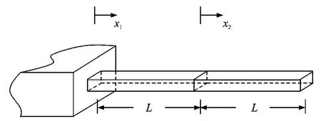
Fig.1 Cantilever structure of coupled beam
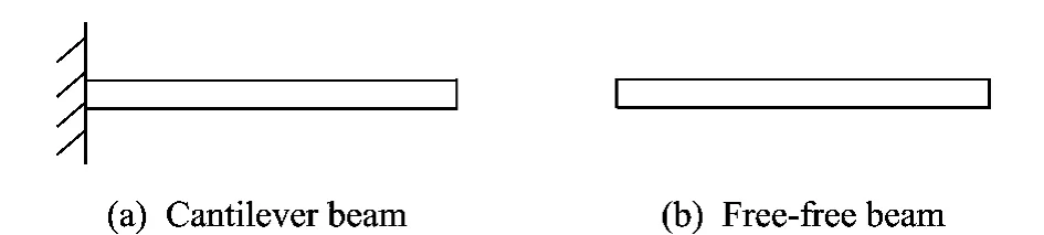
Fig.2 Cantilever and free-free beams
In the absence of damping,the motion equation of single uniform Euler-Bernoulli beam with constant cross-section may be written in the form
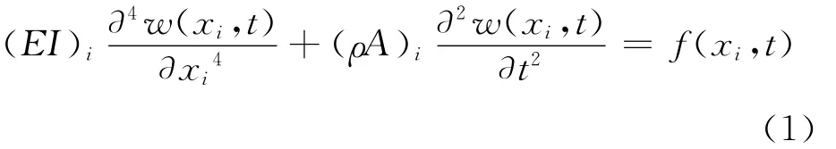
where w(x1,t)and w(x2,t)are the transversal deflection of the first beam and the second beam,respectively,f(x1,t)and f(x2,t)the external disturbance of the first beam and the second beam,respectively,Edenotes the Young′s modulus,Ithe area moment of inertia,ρthe density,Athe cross-sectional area.
The bending moment Mand shear force Q transmitted through an arbitrary section of the beam may be expressed as

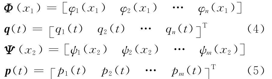
Using assumed mode method,the displacement of the beam 1and beam 2can be discretized as

whereΦ (x1)andΨ (x2)represent the mode functions of transverse vibrations of beam 1and beam 2,respectively,q(t)and p(t)the modal coordinates of transverse vibrations of beam 1and beam 2,respectively.The quantities are given by
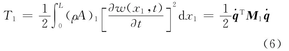
The kinetic energy of the beam 1can be expressed as
The potential energy of the beam 1can be written as

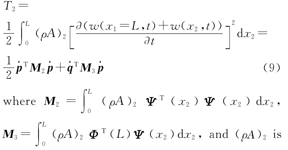
The kinetic energy of the beam 2is given by
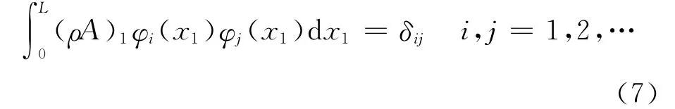
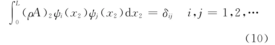
the mass per unit length of the beam 2.Here,the mode shapes are assumed to be mass-normalized such that
The potential energy of the beam 2is expressed as
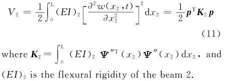
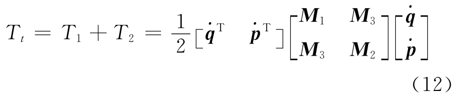
Therefore,the kinetic energy of two-beam structures can be written as
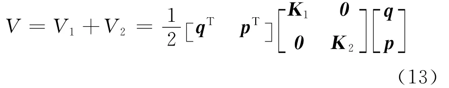
The potential energy of the structures is expressed as
Substructure synthesis is a method whereby a structure is regarded as an assemblage of substructures,each of which is modeled separately and made to act as a single structure by imposing certain geometric compatibility at boundaries between two adjacent substructures[16].Therefore,using the substructure synthesis method,the coupled structure is regarded as a cantilever beam and a free-free beam,and applying continuity and equilibrium of the beam junction,dependent modal coordinates [qTpT]of substructures can be transformed the independent modal coordinates of the coupled structure.
Since the displacement and slope are continuous,furthermore,by considering the equilibrium of the beam junction,constraint equations can be written as
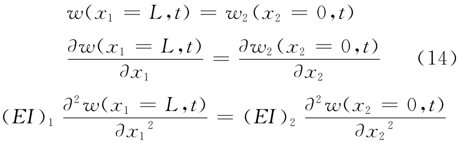
From Eqs.(14-15),the following can be obtained.
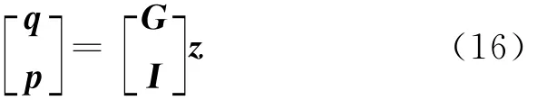
where Iis the identical matrix,matrix Gcan be determined by Eqs.(14-15),and z=[z1z2…zt]Trepresents modal coordinates of transverse vibrations of two-beam structures.
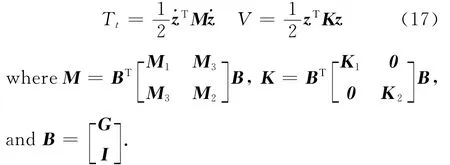
Substituting Eq.(16)into Eqs.(12-13),we have
According to the Clapeyron Principle,the work done by the external load can be expressed as

Obviously,the natural frequencies of the structures can be determined by Mand K.
2 FEEDBACK WAVE CONTROL
Vibrations can be regarded as the superstition of the waves traveling through the structure.In this paper,collocated force/sensor negative feedback control is assumed to be applied.In the frequency domain,the wave-control force is given by

where Hw(ω)is frequency-dependent and complex[5].Note that the amplitudes of any incident near-field waves are neglected.
A propagating wave is incident on the discontinuity and gives rise to reflected and transmitted waves.In order to determin Hw(ω),the wave reflection and transmission coefficients at point discontinuities are needed to be calculated.
2.1 Wave transmission and reflection at beam junction
If a concentrated harmonic load is applied,at any point,to the beam,four free flexural waves will emanate from this point.
Let two beams differed by wave-number and bending stiffness be joined at x3=0.A positivepropagating wave is incident on the beam junction and gives rise to reflected and transmitted propagating and near-field waves,as shown in Fig.3.
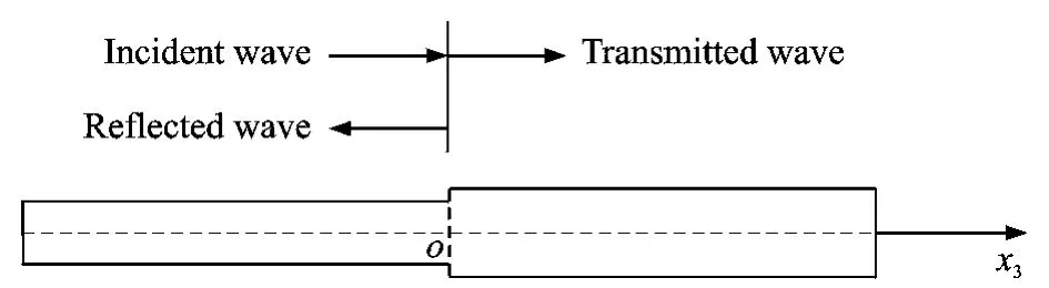
Fig.3 Reflection and transmission of waves at beam junction
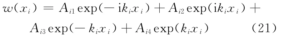
The displacement of the beam w- (x3)and w+(x3)in the regions x3≤0and x3≥0are given by
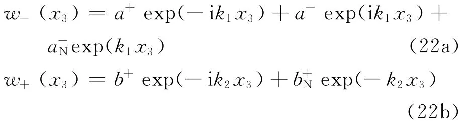
where the time dependence exp(iωt)has been suppressed,a+denotes the wave amplitude of incident propagating waves,a-the wave amplitude of reflected propagating waves,a-Nthe wave am-plitude of reflected near-field waves,b+the wave amplitude of transmitted propagating waves,and b+Nthe wave amplitude of transmitted near-field waves.The subscripts 1and 2refer to the incident and transmitted sides of the junction,respectively.
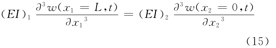
Since the displacement,slope,bending moment and shear force are all continuous at the junction[13],we have
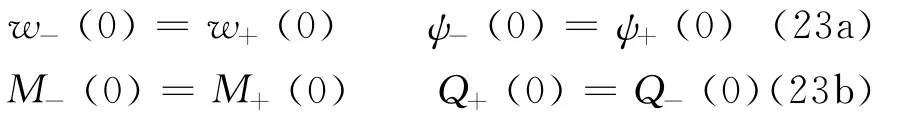
where sign″-″and″+″denote the corresponding mechanical quantity in the regions x3≤0and x3≥0,respectively.
Substituting Eq.(22)into Eq.(23),the reflection and transmission coefficients can be expressed as

whereα=k2/k1andβ=(EIK2)2/(EIK)1represent the ratios of wave-number and bending wave impedance,t1and t2the transmission coefficients,and r1and r2the reflection coefficients.
If the material is the same on both sides of the beam junction,we have

whereσ=h2/h1denotes the thickness ratio of two beams.
For an incident propagating wave,the power carried in a propagating wave is proportional to the square of wave amplitude[6,13].The reflection efficiency,the ratio of reflected to incident power is given by Er(σ)=|r1|2,and the power transmitted is given by Et=1-Er(σ)=|t1|2σ3/2.Therefore the power reflected and transmitted per unit incident power is Ep(σ)=|r1|2+|t1|2σ3/2.Transmitted energy depends onσ.
2.2 Wave transmission and reflection at control location
The power is mostly transmitted at the beam junction whenσis close to 1.The power is mostly reflected at the beam junction whenσapproaches 0.Therefore wave control is used somewhere downstream to absorb energy associated with the transmitted propagating wave of the beam junction whenσis close to 1as shown in Fig.4(a).Whenσapproaches 0,wave control is used somewhere upstream to absorb energy associated with the transmitted propagating wave of beam junction as shown in Fig.4(b).Transmitted (or reflected)propagating wave of the beam junction is incident on the control location and gives rise to reflected and transmitted propagating and nearfield waves.

Fig.4 Schematic diagram of feedback control
At first,consider the first case whenσis close to 1as shown in Fig.4(a).Wave control is applied at position x4=0.The displacement of the beamw-(x4)and w+(x4)in the regions x4≤0and x4≥0are given by
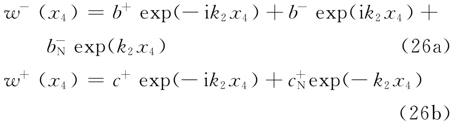
where the time dependence exp(iωt)has been suppressed.
For the same reason described in Section 2.1,the reflection and transmission coefficients at the control location can be expressed as
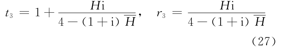
where t3and t4are the transmission coefficients,and r3and r4the reflection coefficients.
In this paper,the controller is designed to absorb vibrational energy by adding optimal damping to the structure.SupposingH(ω)=(1+i)ωg,the power carried in a propagating wave is proportional to the square of the wave amplitude.The performance index of optimal control is to make the dissipated energy at control location the maximum.In other words,the optimal control gain gcan be found by assuming that a wave is incident on onside of the control location and then by designing the control gain so as to maximize the absorb incoming energy,namely to minimize|r3|2|t1|2σ3/2+|t3|2|t1|2σ3/2.
Therefore the power reflected and transmitted at control location is given by
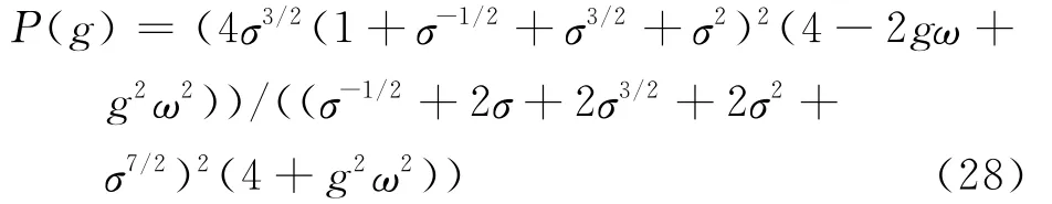
Then the frequency response of the optimal controller is given by

where g=2/ω.
Next,consider the second case when the power is mostly reflected at the beam junction (σ approaches 0)as shown in Fig.4(b).
For the same reason as stated above,the reflection and transmission coefficients at the control location can be expressed as

where t3and t4are the transmission coefficients,r3and r4the reflection coefficients.
2.3 Controller design
The optimal controller is noncausal[5-6].Hence,a real-time implementation must be some approximations to this ideal.PD feedback control is implemented,with the controller tuned so that it is equal to the optimal controller at some specific frequenciesωd.The controller then has the frequency response

where c1=ωdgand c2=g.
If the force is applied at a point xi=xw(i=1,2),then the wave-control force is fw=(w,xi,t)δ(xitxw).For tuned PD control,substituting Eq.(31)to Eq.(20),using Laplace transform,this becomes
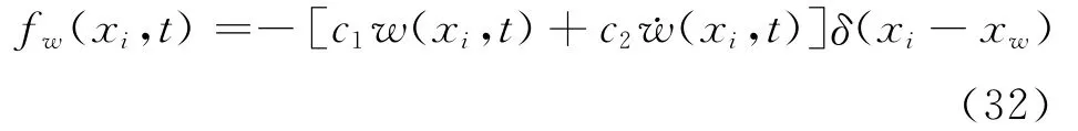
For collocated wave control,and with the control force approximated by Eq.(32),the equations of motion can thus be written in matrix form as

3 NUMERICAL EXAMPLES
In this section,some numerical results are presented.In what follows,several dimensionless parameters are:L=1,the first natural frequency of the first beamω1=1,the thickness ratio of two beamsσ=0.90,0.21and 0.05,and the corresponding non-dimensional natural frequencies ωi(i=1,2,…,9)are given in Tables 1-3.

Table 1 First nine nondimensional natural frequencies of system (σ=0.90)

Table 2 First nine nondimensional natural frequencies of system (σ=0.21)

Table 3 First nine nondimensional natural frequencies of system (σ=0.05)
A disturbance force is applied at x1=0.10L.Simulation results are shown in Figs.5-14.In Figs.6,14,the wave-control force is applied at x2=Lwhenσ=0.90.In Fig.8,the wave-control force is applied at x1=0.15L whenσ=0.05.In Fig.10,the wave-control force is applied at x2=L whenσ=0.21 (reflected energy at the beam junction is almost equal to transmitted energy of the beam junction).In Fig.11,the wave-control force is applied at x1=0.15L.In Fig.12,two wave controllers are applied at x1=0.15L and x2=L.Numerical results show the response at x2=0.75L per unit disturbance force. In Figs.5-12,the value of ordinate is prescribed as common logarithm of the actual deflection.
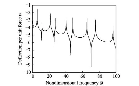
Fig.5 Frequency response before wave control(σ=0.90)
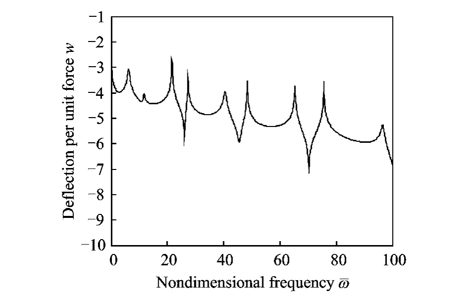
Fig.6 Frequency response after wave control(σ=0.90,x2=L)
The positions of these points are chosen so as to avoid the nodes of the modes.The controlled and uncontrolled frequency responses are compared.In the approximation that tuned PD control,the controller is tuned to be optimal atωd=10.
Figs.5,6show that the frequency responses before and after wave control whenσ=0.90.The power is mostly transmitted at the beam junction whenσis close to 1,so wave controller is applied at the second beam for good performance.Without control,sharp resonances can be observed.While after wave control,controllers add damping to the structure.Energy of structure is absorbed.Sharp resonances are weakened.
Figs.7,8show that the frequency responses before and after wave control whenσ=0.05.The power is mostly reflected at the beam junction whenσapproaches 0.Therefore,wave control is applied at the first beam.In Figs.6,8,relatively poor performance can be seen.The degradation of the performance is due to the fact that the point of application of the wave controller lies to the nodes of the modes.Such effects depend on the specific form and location of the wave controller,the conclusion is same as Refs.[5,12].They can be minimized by the suitable application of two or more wave controllers.

Fig.7 Frequency response before wave control(σ=0.05)
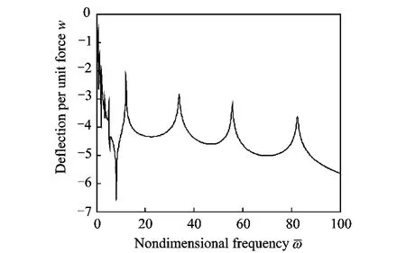
Fig.8 Frequency response after wave control(σ=0.05,x1=0.15L)
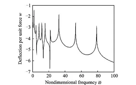
Fig.9 Frequency response before wave control(σ=0.21)
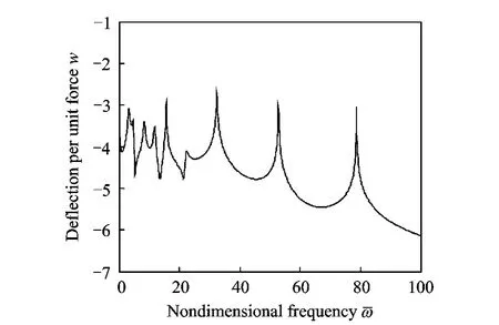
Fig.10 Frequency response after wave control(σ=0.21,x2=L)

Fig.11 Frequency response after wave control(σ=0.21,x1=0.15L)
Figs.9-12show that the frequency respon-ses before and after wave control whenσ=0.21.Fig.10shows wave controller absorbs vibrational energy,especially at lower frequencies.Fig.11 shows wave controller absorbs vibrational energy,especially at higher frequencies.In Figs.10,11,relatively poor performance can be seen when wave controller is only applied at the downstream of the beam junction or upstream of the beam junction,whereas Fig.12gives better performance.In fact,reflected energy at the beam junc-tion is almost equal to transmitted energy at the beam junction whenσapproaches 0.21,so wave controllers are ought to be applied at not only the first beam but also the second beam for better performance.One controller absorbs reflected energy,and the other absorbs transmitted energy.Figs.13,14show that the time responses before and after wave control whenσ=0.90.
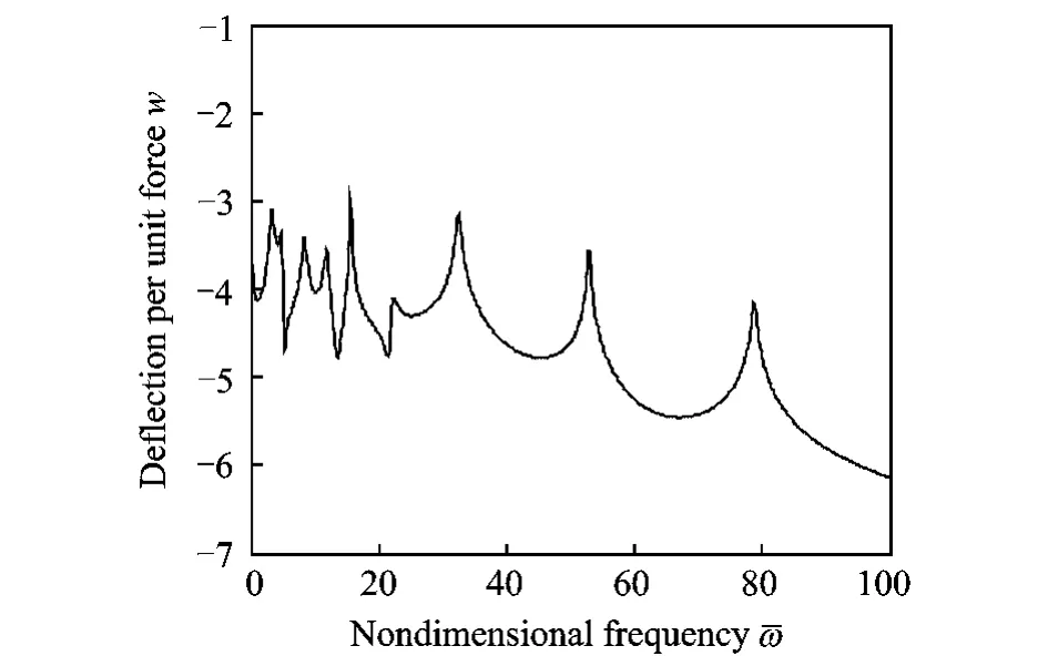
Fig.12 Frequency response after wave control(σ=0.21,x1=0.15L,x2=L)
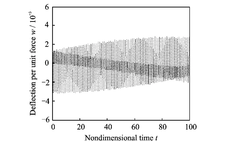
Fig.13 Time response before wave control(σ=0.90)
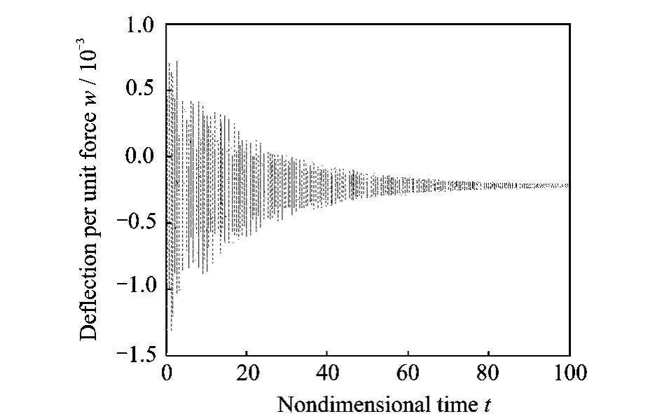
Fig.14 Time response after wave control(σ=0.90)
4 CONCLUSION
This paper presents the theoretical analysis and numerical results of wave control of twobeam structures.Wave control is used to control the wave motion of the structures.The incident propagating wave is reflected and transmitted at beam junction,and wave reflection and transmission coefficients at beam junction are also be decided by the thickness ratio of two coupled beams.The power is mostly transmitted at the beam junction when the thickness ratioσis close to 1.Whenσis close to 0,the power is mostly reflected at the beam junction.Therefore wave control is used somewhere downstream to absorb energy associated with the transmitted propagating wave of the beam junction whenσis close to 1.Whenσis close to 0,wave control is used somewhere upstream to absorb energy associated with the transmitted propagating wave of the beam junction.In other circumstances,there is not only reflected energy at the beam junction but also transmitted energy.Now,better performance can be achieved by applying wave controllers to two sides of beam junction.One controller absorbs reflected energy,and the other absorbs transmitted energy.
Control gain is designed in frequency domain.PD control is adopted.In the time domain,this corresponds to a tuned spring-damper combination.The results show that the wave control is efficient for two coupled beams.Similarly,the wave controller is designed for two coupled plates lying in the x-y plane and its efficiency is proved.
[1] Ma Xingrui,Gou Xingyu,Li Tieshou,et al.Development generalization of spacecraft dynamics[J].Journal of Astronautics,2000,21(3):1-5.(in Chinese)
[2] Wang Liang,Chen Huaihai,He xudong,et al.Active vibration control of axially moving cantilever beam by magnetic force[J].Journal of Nanjing University of Aeronautics & Astronautics,2010,42(5):568-573.(in Chinese)
[3] Miller D,Hall S,Flotow A von.Optimal control of power flow at structural junctions[J].Journal of Sound and Vibration,1990,140(3):475-497.
[4] Jha R,Bailey A,Ahmadi G.Combined active and passive control of space structure vibrations during launch[C]//44th AIAA/ASME/AHS Structures,Structural Dynamics,and Materials Conference.Norfolk,Virginia,USA:AIAA,2003.
[5] Mei C,Mace B R,Jones R W.Hybrid wave/mode active vibration control[J].Journal of Sound and Vibration,2001,247(5):765-784.
[6] Chen T,Hu C,Huang W H.Vibration control of cantilevered Mindlin-type plates[J].Journal of Sound and Vibration,2009,320(1/2):221-234.
[7] Gardonio P,Elliott S J.Active control of waves on a one-dimensional structure with a scattering termination[J].Journal of Sound and Vibration,1996,192(3):701-730.
[8] Brennan M J.Control of flexural waves on a beam using a tunable vibration neutralizer[J].Journal of Sound and Vibration,1998,222(3):389-407.
[9] Carvalho M O M,Zindeluk M.Active control of waves in a Timoshenko beam[J].International Journal of Solids and Structures,2001,38(10-13):1749-1764.
[10]Halkyard C R,Mace B R.Feedforward adaptive control of flexural vibration in a beam using wave amplitudes[J].Journal of Sound and Vibration,2002,254(1):117-141.
[11]EL-Khatib H M,Mace B R,Brennan M J.Suppression of bending waves in a beam using a tuned vibration absorber[J].Journal of Sound and Vibration,2005,288(4/5):1157-1175.
[12]Hu Chao,Chen Tao,Huang Wenhu.Active vibration control of Timoshenko beam based on hybrid wave/mode method[J].Acta Aeronautica et Astronautica Sinica,2007,28(2):301-308.(in Chinese)
[13]Mace B R.Wave reflection and transmission in beams[J].Journal of Sound and Vibration,1984,97(2):237-246.
[14]Mead D J.Waves and modes in finite beams:Application of the phase-closure principle[J].Journal of Sound and Vibration,1994,71(5):695-702.
[15]Svensson J L,Andersson P B U,Kropp W.On the design of structure junctions for the purpose of hybrid passive-active vibration control[J].Journal of Sound and Vibration,2010,329(9):1274-1288.
[16]Meirovitch L.Dynamics and control of structures[M].New York:Wiley,1990.
猜你喜欢
Chinese Physics B(2022年6期)2022-06-29
红蜻蜓·低年级(2021年6期)2021-08-23
红蜻蜓·低年级(2021年6期)2021-08-23
湖北理工学院学报(人文社会科学版)(2021年4期)2021-07-14
辽河(2020年4期)2020-04-23
美术文献(2017年11期)2017-03-09
高中生·职教与就业(2013年5期)2013-06-18
恋爱婚姻家庭·青春(2009年8期)2009-09-02
廉政瞭望(2006年1期)2006-02-27
 Transactions of Nanjing University of Aeronautics and Astronautics2013年2期
- Transactions of Nanjing University of Aeronautics and Astronautics的其它文章
- FLEXURAL CAPACITY OF RC BEAM STRENGTHENED WITH PRESTRESSED C/AFRP SHEETS
- IMPROVED DOPPLER WARPING METHOD FOR AIRBORNE RADAR WITH NON-SIDELOOKING ARRAY
- MINIMUM ATTRIBUTE CO-REDUCTION ALGORITHM BASED ON MULTILEVEL EVOLUTIONARY TREE WITH SELF-ADAPTIVE SUBPOPULATIONS
- OUTPUT MAXIMIZATION CONTROL FOR VSCF WIND ENERGY CONVERSION SYSTEM USING EXTREMUM CONTROL STRATEGY
- DISCONTINUOUS GALERKIN TIME DOMAIN METHOD FOR SOI THIN-RIDGE WAVEGUIDE PROBLEM
- MULTI-OBJECTIVE PROGRAMMING FOR AIRPORT GATE REASSIGNMENT