
Optimal Delayed Control of Nonlinear Vibration Resonances of Single Degree of Freedom System*
2014-04-24 10:53LiuCanchang刘灿昌JiHongli季宏丽SunHuiyu孙慧玉QiuJinhao裘进浩LiuLu刘露
Liu Canchang(刘灿昌),Ji Hongli(季宏丽),Sun Huiyu(孙慧玉) Qiu Jinhao(裘进浩),Liu Lu(刘露)
1.State Key Laboratory of Mechanics and Control of Mechanical Structures,College of Aerospace Engineering,Nanjing University of Aeronautics and Astronautics,Nanjing,210016,P.R.China;2.School of Transportation and Vehicle Engineering,Shandong University of Technology,Zibo,255049,P.R.China
1 Introduction
In the past decade,a substantial amount of research have been carried out to understand the effects of time delay on the behavior of nonlinear dynamical systems which are controlled by the linear or nonlinear feedback controllers to mitigate the vibrations.The time delays exist not only between sampled signal output and control signal input,but also arise while the controller is calculating or performing.The intrinsic timedelays inevitably bring a defective effect on the structural vibration control.However,most researches paid attention to the defective impact caused by time delay.Research is sparse on the use of time delay for vibration attenuation control.The delayed terms of the nonlinear systems have an important role in the vibration control engineering.For this reason,understanding of the role played by delayed vibration control of the nonlinear systems is essential.
Recently,local stability and bifurcations of the nonlinear vibration system have received considerable attention[1-2].Li et al[3]studied the response of a Duffing-Van der Pol oscillator under delayed feedback control.Ji and Leung[4]studied the primary,super-harmonic,and sub-harmonic resonances of a harmonically excited nonlinear single-degree-of-freedom(SDOF)system with two distinct time-delays in the linear state feedback.Qian and Tang[5]discussed the primary resonance and the sub-harmonic resonances of a non-linear beam under moving load based on timedelay feedback controllers.Daqaq et al[6]presented a comprehensive report on the effect of feedback delays on the non-linear vibrations of a piezoelectric actuated cantilever beam.Their work also includes the analysis of the effect of feedback delays on a beam subjected to harmonic based excitations.
In recent years,the technique of delayed feedback control has been utilized as an effective tool in controlling vibrations of a wide variety of mechanical systems.Olgac et al[7]used the method of delayed resonators to control the vibration of mechanical system.The time-delayed acceleration feedback control was utilized to study the vibration of a continuous system[8].The timedelayed velocity feedback control technique was applied for controlling the vibration of torsional mechanisms[9].Jalili et al[10]used time-delayed feedback resonators to control the vibration of discrete multi-degree-of-freedom systems.Naik and Singru[11-12]studied the stability,Hopf bifurcation and chaotic vibration of a nonlinear oscillator with multiple time-delays.Zhao et al[13]used the delayed feedback control technique to suppress the vibration of vertical displacement in a two-degree-of-freedom nonlinear system subjected to external excitation.Active control is applied in the vibration of the linear and nonlinear vibration structures[14-15].The authors mentioned above had reservations on the selection of feedback gains and time-delays,which can enhance the control performance of nonlinear system or change the position of the bifurcation point.However,all these publications missed to report method for choosing the optimized control parameters and time delays for keeping the system stable.
The main purpose of this paper is to present an optimum control method for SDOF nonlinear vibration system.This system takes the time delay as a control factor that can turn the defective effect into the favorable effect.This system also chooses the optimized time delay used in the vibration attenuation of an intelligent structure,which can reduce the input energy and simultaneously improve the system control effect.A method of determining the regions of the time delays and feedback gains is given based on the analysis of the stability conditions of eigenvalue equation.The control parameters are calculated by minimum optimal method,which takes the attenua-tion ratio as the objective function.Optimal controllers are designed to control the dynamic behavior of the nonlinear dynamic system.
2 Equation Derivation
The dimensionless equation of motion of a non-linear SDOF system subjected to a harmonic excitation with two distinct time-delays can be written as follows[4]

where gdand gvare the feedback gain parameters of displacement and velocity,respectively.
In the case of primary resonance,the frequency is expressed as

By using the method of multiple scales,an approximate solution to Eq.(1)can be written as

where Tn=εnt,n=0,1,2,….
By substituting the Eq.(3)into Eq.(1)and equating the coefficients of like powers ofε,the following are obtained
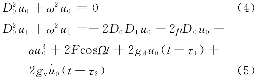
where Dn=∂/∂Tn,n=0,1,2,….
The solution to Eq.(1)is

where cc stands for complex conjugates.By substituting the solution of Eq.(6)into Eq.(5),the equation of the secular terms can be written as
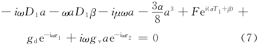
Letγ=σT1-β.By separating the real and imaginary parts of Eq.(7),the amplitude aand phaseγof the response governed by the following polar form of modulation equations can be expressed as

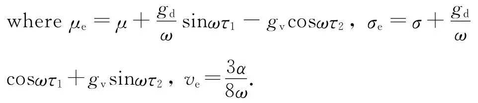
Setting D1a=D1γ=0,the following can be obtained
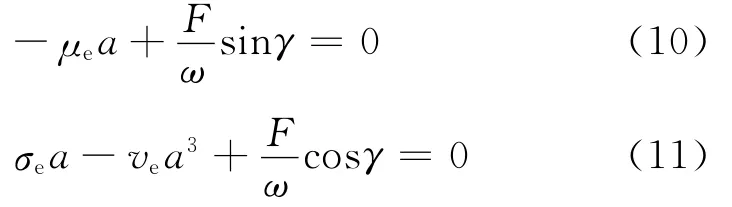
From Eqs.(10,11),the frequency-response equation can be expressed as

The peak amplitude at primary resonance response obtained from Eq.(12)can be written as

For the purpose of comparison,peak amplitude of nonlinear primary oscillator without control will be considered.
The equation of motion of the nonlinear primary oscillator without control is

The corresponding peak amplitude for the nonlinear primary oscillator without control is

As it is difficult to find an analytical solution for a nonlinear system,the performance of the vibration controllers on the reduction of nonlinear vibrations cannot be studied using a similar procedure for discussing the ratio of response amplitude for the linear system.Therefore,an attenuation ratio is utilized to evaluate the performance of the vibration control by using aproportion of vibration peak of primary resonance with and without control.The attenuation ratio can be written as[16-17]

In this paper,μis assumed as positive.As defined by Eq.(16),a small value of the attenuation ratio Rindicates a large reduction in the nonlinear vibrations of the primary system.A smaller attenuation rate can be obtained by selecting proper parameters for feedback gains and time delays.
3 Design of Primary Resonance Vibration Controllers
The stability of the solutions is determined by the eigenvalues of the corresponding Jacobian matrix of Eqs.(8,9).The corresponding eigenvalues are the roots of the equation

The sum of two eigenvalues is-2μe,which varies with feedback gains and time delays.If μe>0,the sum of two eigenvalues is negative,which means that at least one of the two eigenvalues will have a negative real part.Based on the above analysis,the sufficient condition for ensuring the system stability is[3]

The value of f(σe)is positive when there is no real solution to the equation f(σe)=0.By assuming,it gains
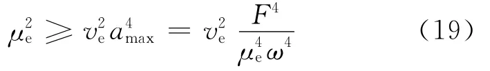
For simplicity,the time-delays are expressed in the forms ofτ1=τandτ2=φ+ωτ.The parameterμebecomes
As the phase of velocity is ahead of displacement byπ/2,the phase differenceφcan be assumed as π/2[4].Eq.(20)can be modified as
Substituting Eq.(20)into Eq.(19)and considering Eq.(21),the following expression is obtained

The region of the stable vibration control parameters can be obtained as

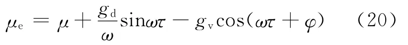
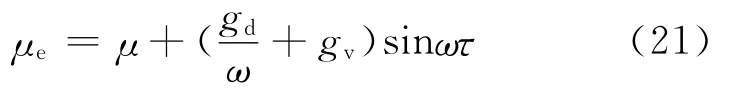
When there are two real solutions to equation f(σe)=0,the solutions are

As the image of f(σe)=0is a parabola open upwards,the inequality f(σe)>0is satisfied when σe<σ-eandσe>σ+e.By reducing or enlarging the roots of the equation f(σe)=0,the following inequalities are obtained
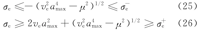
Considering the formula ofσkand inequality given by Eq.(25),the stable vibration region is obtained as

Taking into account the relationship Eq.(26),there is

4 Optimization of Parameters for Controller Design
The regions of feedback parameters are obtained based on the analysis of the stability conditions of nonlinear vibration system.However,the optimal control parameters of the system are difficult to obtain.Taking the attenuation ratio as the objective function,the optimal feedback control parameters can be calculated by using an optimization method.An optimal analysis is carried out by considering the cases with no solution or with two solutions for the critical equation.
Parametric optimization design for the case of critical equation without a solution is

Subjected to

Parametric optimization design in the case of criti-cal equation with two solutions is

5 Simulation Research
This paper reports a study on the nonlinear vibration control for SDOF system.The parameters selected areα=1,ω=3.0andμ=0.05.
Fig.1shows the variation of peak amplitude amaxwith time delays for feedback gains.It can be easily seen that amaxvaries significantly with increasing time delay.For the value of fixed amplitude of excitation and feedback gains,the amplitudes of the vibration in the regions of 0—1.2 and 2.2—3.2are smaller than those in the regions of 1.2—2.2and 3.2—3.5.For fixed timedelays,with increasing feedback gains the peak amplitude decreases.The properly selected values of time-delays and feedback gains give a smaller peak amplitude amax.

Fig.1 Variation of amaxwith time delay for different feedback gains
Fig.2shows the variation of attenuation ratio Rwith time-delays for different feedback gains.As evident from the figure,for a fixed amplitude value of excitation,a smaller value of the attenuation ratio Rsignifies a larger reduction in the nonlinear vibrations of the system.A properly selected value of time delays gives a larger positive value ofμeand a smaller attenuation ratio of R.

Fig.2 Variation of Rwith time delay for different feedback gains
Taking the attenuation ratio as the objective function,the optimal feedback control parameters can be determined by using the minimum optimal method.In the formulation of inequality Eq.(22),the value of gsτshould be positive for obtaining improvement in control performance.A larger value of gsτresults in a smaller attenuation rate of Rand a better control performance.It is also found that gsτis a function of excitation amplitude F.With increasing value of Fthe value of control parameter should be increased for reducing the vibration.The effect of the excitation amplitude on the stable minimum control parameters for three sets of time-delays is shown in Figs.3,4.The stable maximum feedback gain is shown in Fig.5.For area above the curve,the feedback gains can lead to a stable control performance while that below the curve is unstable.The stable minimum or maximum feedback gain varies with change of the time delays and amplitude of excitation.In the region of time delay 0—π/2ω,a larger value of time delay requires a smaller feedback gain to control the vibration of the system.The smallest feedback gain g can be used to reduce the vibration,therefore the optimal control time-delays can be obtained whenτ=π/2ω.The time delay can be taken as a control factor to improve the control performance as well as the feedback gains.A good control performance can be obtained by selecting optimal time delays.Fig.6shows the graphs for primary resonance of vi-bration system for three different sets of feedback gains.There is no jump or hysteresis phenomenon when gsτ=0.025or 0.035.This suggests that saddle node bifurcation and jump phenomenon can be eliminated by choosing stable values of the feedback gains.Three solutions exist when gsτ=0.005.The bending of the frequency response curves is due to jump phenomenon.Moreover,the peak amplitude of the primary resonance response at gsτ=0.035is the smallest among the three cases.The vibration controllers can effectively suppress the amplitude oscillations of the nonlinear oscillator.Hence,by choosing optimal feedback gains and time delays of the controllers,the primary resonance response of the nonlinear oscillator can be reduced.

Fig.3 Stable minimum control parameters gτ1 for three sets of time delays

Fig.4 Stable minimum control parameters gτ2 for three sets of time delays

Fig.5 Stable maximum control parameters gτ3 for three sets of time delays

Fig.6 Frequency-response graphs for primary resonance for three sets of feedback gains
Fig.7shows the primary resonance graphs of vibration system for three different sets of the time delays.The parameters are gd=0.2,gv=0.06,and F=0.1.There is no jump or hysteresis phenomenon whenτ=π/6ωorτ=π/3ω.The saddle node bifurcation and jump phenomenon can be eliminated by choosing certain numerical values of time delays.Three solutions exist in a region of coexistence whenτ=0.The peak amplitude of the primary resonance response atτ=π/3ωis the smallest among the three cases.The time-delays chosen correctly can effectively suppress the amplitude oscillations of the nonlinear oscillator.
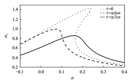
Fig.7 Frequency-response graphs for primary resonance for three sets of time delays
The amplitude of excitation Fis 0.1.It can be determined that the product of feedback gain gsτis higher than 0.025when the characteristic equation has no solution.Assumingτ=π/6ωthe optimal feedback gains can be calculated as gcτ≥0.567for the case of characteristic equation with two solutions.
Fig.8gives the numerical result of the control performance of the nonlinear vibration system with delayed displacement and velocity controllers.It is evident that the vibration amplitude is mitigated.In the numerical calculation,the control dampingμeand tune coefficientσeare approximate replacements toμandσ,respectively.The Runge-Kutta method is used to obtain the numerical result for the vibration displacement.The feedback gains of displacement and velocity are gd=0.5,gv=0.4,respectively.The damping of the system isμ=0.1.Time delay isτ=π/3ω.The frequency of the excitation isΩ=3.1.
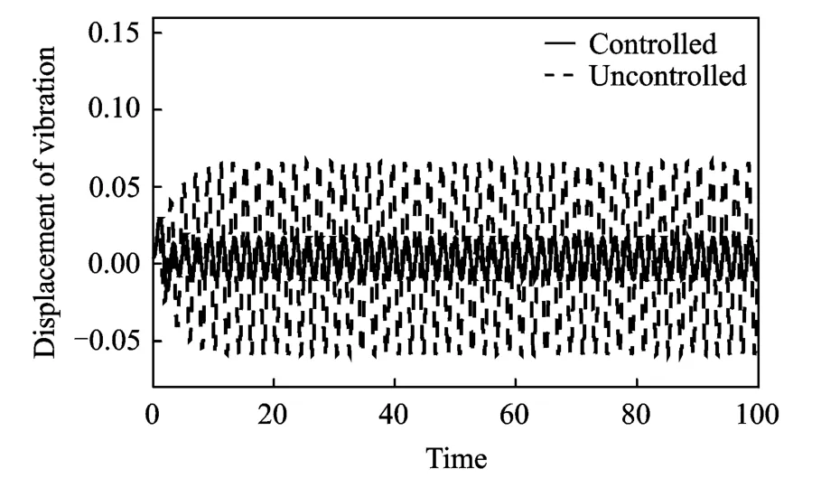
Fig.8 Control performance of nonlinear vibration system with delayed displacement and velocity controllers
6 Conclusions
The regions of the time delays and feedback gains are obtained by enlarging or reducing the inequalities of production of eigenvalue equation roots.Taking the attenuation ratio as the objective function,the optimal control parameters of feedback gains and time delays are determined using the method of minimum optimal attenuation ratio.
Time-delays feedback control is a singlechannel control strategy and its design is relatively simple.Compared to damping force controller,the delayed controller is controlled with two parameters(feedback gains parameter and time delayed parameter)which can be independently adjusted.Therefore,the scope of design and adjustment are much wider.A delayed circuit is used in the controller algorithm and it has simple structure,low energy consumption and is easy to implement.
[1] Hu H Y,Dowell E H,Virgin L N.Resonances of a harmonically forced Duffing oscillator with the timedelay state feedback[J].Nonlinear Dynamics,1998,15:311-327.
[2] Xu J,Pei L J.Advances in dynamics for delayed system[J].Advanced Mechanics,2006,36:17-30.(in Chinese)
[3] Li X Y,Ji J C,Hansen C H.The response of a Duffing-van der Pol oscillator under delayed feedback control[J].Journal of Sound and Vibration,2006,291:644-655.
[4] Ji J C,Leung A Y T.Responses of a non-linear s.d.o.f.system with two time-delays in linear feedback control[J].Journal of Sound and Vibration,2002,253:985-1000.
[5] Qian C Z,Tang J S.A time delay control for a nonlinear dynamic beam under moving load[J].Journal of Sound and Vibration,2008,309:1-8.
[6] Daqaq M F,Alhazza K A,Arafat H N.Non-linear vibrations of cantilever beams with feedback delays[J].J Nonlinear Mechanics,2008,43:962-978.
[7] Olgac N,Hoim-Hansen B.A noval active vibration absorption technique:Delayed resonator[J].Journal of Sound and Vibration,1994,176:93-104.
[8] Olgac N,Jalili N.Modal analysis of flexible beams with delayed resonator vibration absorber:theory and experiments[J].Journal of Sound and Vibration,1998,218(2):307-331.
[9] Hosek M,Elmali H,Olgac N.Tunable torsional vibration absorber:the centrifugal delayed resonator[J].Journal of Sound and Vibration,1997,205(2):151-165.
[10]Jalili N,Olgac N.Multiple delayed resonator vibration absorbers for multi-degree-of-freedom mechanical structures[J].Journal of Sound and Vibration,1999,223(4):567-585.
[11]Naik R D,Singru P M.Resonance,stability and chaotic vibration of a quarter-car vehicle model with time-delay feedback[J].Commun Nonlinear Sci Numer Simulat,2011(16):3397-3410.
[12]Naik R D,Singru P M.Stability and Hopf bifurcation of a Nonlinear oscillator with multiple time-delays[J].Chaos,Solitons and Fractals,2012(45):1387-1396.
[13]Zhao Y Y,Xu J.Effects of delayed feedback control on nonlinear vibration absorber system[J].Journal of Sound and Vibration,2007(308):212-230.
[14]Chen T,Wang L G,Feng G F.Active vibration control of two-beam structures[J].Transactions of Nanjing University of Aeronautics and Astronautics,2013,30(2):193-201.
[15]Hu Y Y,Jiang C S.Robust control of a class of nonlinear system with time-varying parametric uncertainties[J].Transactions of Nanjing University of Aeronautics and Astronautics,2003,20(1):97-102.
[16]Ji J C,Zhang N.Suppression of the primary resonance vibrations of a forced nonlinear system using a dynamic vibration absorber[J].Journal of Sound and Vibration,2010,329:2044-2056.
[17]Ji J C,Zhang N.Suppression of super-harmonic resonance response using a linear vibration Absorber[J].Mechanics Research Communications,2011(38):411-416.
 Transactions of Nanjing University of Aeronautics and Astronautics2014年1期
- Transactions of Nanjing University of Aeronautics and Astronautics的其它文章
- Lattice Boltzmann Flux Solver:An Efficient Approach for Numerical Simulation of Fluid Flows*
- Experimental Investigation on Flow and Heat Transfer of Jet Impingement inside a Semi-Confined Smooth Channel*
- Flapping Characteristics of 2DSubmerged Turbulent Jets in Narrow Channels*
- Critical Length of Double-Walled Carbon Nanotubes Based Oscillators*
- Identification of Time-Varying Modal Parameters for Thermo-Elastic Structure Subject to Unsteady Heating*
- Dynamics of Rotor Drop on New Type Catcher Bearing*