
Hydraulics of a multiple slit-type energy dissipater*
2014-06-01 12:29WUJianhua吴建华YAOLi姚莉MAFei马飞
水动力学研究与进展 B辑 2014年1期
WU Jian-hua (吴建华), YAO Li (姚莉), MA Fei (马飞)
College of Water Conservancy and Hydropower Engineering, Hohai University, Nanjing 210098, China, E-mail: jhwu@hhu.edu.cn
WU Wei-wei (吴伟伟)
Hydraulic Structures Design Division, Hydrochina Huadong Engineering Corporation, Hangzhou 310014, China
Hydraulics of a multiple slit-type energy dissipater*
WU Jian-hua (吴建华), YAO Li (姚莉), MA Fei (马飞)
College of Water Conservancy and Hydropower Engineering, Hohai University, Nanjing 210098, China, E-mail: jhwu@hhu.edu.cn
WU Wei-wei (吴伟伟)
Hydraulic Structures Design Division, Hydrochina Huadong Engineering Corporation, Hangzhou 310014, China
(Received October 12, 2013, Revised January 6, 2014)
With the constructions of high dam projects in China, the energy dissipation downstream of a dam becomes a serious concern. In this study, a multiple slit-type energy dissipater, with different reduction size slits in the outlet, is developed on the basis of conventional slit-type energy dissipaters, aiming to enhance the energy dissipation through the turbulence and the friction between the different layers of the jet flow and the air entrainment due to the increased surface of the flow to the air. The hydraulic characteristics of the energy dissipater are experimentally investigated by means of three sets of physical models in nine cases, to characterize the geometric parameters with suitable performance. The main concerns are the flow regime, the jet flow trajectory, the energy dissipation, the cavitation characteristics, and the flow choking. The results indicate that the dissipater enjoys a high energy dissipation ratio with suitable hydraulic performance comparing with the conventional slit-type energy dissipaters.
aerator, cavity length, fin, lateral deflector
Introduction
The energy dissipation downstream of a largescale dam is an important issue, especially in the construction of high dam projects of 300 m level in China[1]. The energy dissipaters, like the ski jump or the hydraulic jump, were studied and employed whenever the velocity at the dam foot is in excess of typically 20 m/s because of problems of stilling basins in terms of cavitation, abrasion and uplift[2].
In recent years, many progresses have been made, as far as practical projects are concerned. Given special geographical conditions downstream of the dam area, a new layout of the stilling basin, namely, the horizontal multiple submerged jets, was designed and successfully used in the Xiangjiaba hydropower project in China, with a higher energy dissipation ratio than the classical hydraulic jump thanks to the effects of shear and friction between multiple jets, as well as the lower velocity near the bottom of the stilling basin[3]. The ski jump hydraulics was discussed systematically in many aspects, such as the flip bucket without and with deflectors[4], the aeration characteristics of ski jump jets[5], some issues about the ski jump design[6], the plunge pool scour of jets[7], and the deflector ski jump hydraulics[8,9]. The findings greatly enriched the hydraulics knowledge of the ski jump and provided some functional principles for energy dissipation designs.
The slit-type energy dissipater (STED), one of the ski jumps, was investigated and used in different outlets of the release works due to the expansion of the flow in vertical and longitudinal directions[10]. This methodology for energy dissipation was adopted in many hydropower projects in China, such as in the middle outlets of the Shannipo hydropower project with the dam height of 119.40 m in Guizhou province, of the Lizhou project with the dam height of 132.00 m in Sichuan province, and of the Dandahe project with the dam height of 137.00 m in Yunnan province.


Fig.1 Parameters of the experimental setup
Similar to the dentated sill on the flip buckets[17], the flow through the STED can be divided into multiple layers in the vertical direction, and the turbulence and the friction between layers could be produced if the multiple slits in the outlet are designed in different sizes, thus, the energy dissipation could be enhanced. This study will be based on this idea. A slit-type energy dissipater with slits of different sizes, called the multiple slit-type energy dissipater (M-STED), is designed in order to enhance the energy dissipation. The hydraulic characteristics are experimentally investigated by means of three sets of physical models in nine cases, including the flow regime, the jet flow trajectory, the energy dissipation, the cavitation performance, and the flow choking.
1. Experimental setup
The experiments were conducted in the Highspeed Flow Laboratory, Hohai University, Nanjing, China. The experimental setup consists of a pump, an approach conduit, a large feeding basin, a test model, and a flow return system (Fig.1(a)).
The feeding basin issues an approach (subscript o) flow of depthhoand average velocityVo, resulting in the approach flow of Froude numberFro=Vo/ (gh)1/2. The water dischargesQare measured with
o discharge measurement weir instruments downstream of the experimental model. The maximum pump capacity is 400 L/s, and the working head is 1.50 m.
The test model, made of perspex, is composed of two parts, with pressure flow and with free-surface flow, respectively. The part with pressure flow is 0.65 m long, 0.15 m in width, and 0.19 m high. The part of free-surface flow is 0.55 m long, 0.15 m in width, and 0.30 m high with the M-STED in the outlet. The geometry of the M-STED is shown in Figs.1(b) and 1(c). The channel widthB=0.15 m, which is reduced tob=0.08 m in the edge of the outlet, and the length of the reduction section is fixed asL= 0.1125 m. In the vertical direction of the heightho, the outlet is divided intonlayers with the same heightcand the slit width ofa1ora2for each case. The drop height is fixed ass=0.08 m.

Table 1 Case names, outlet geometry, and symbols
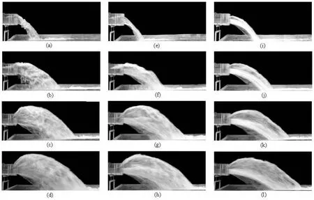
Fig.2 Flow regimes of (a-d) for M00,o=Fr1.286, 2.405, 2.921, 3.174, (e-h) for M14,o=Fr1.071, 2.394, 2.949, 3.919, and (i-l) for M24,o=Fr1.345, 2.374, 2.976, 3.254
The origin of the coordinate system (x,y) is at the tailwater channel bottom below the M-STED end (Fig.1(a)). The maximum (subscript M) elevationyMof the upper jet trajectory and its positionxMare measured with a level instrument. The impact points of both the upperx1and lowerxmjet trajectories onto the tailwater channel are determined visually from the channel side, by extending the jet trajectory.
The test program includes three sets of physical models in nine cases, located with their ends atx=0, they are characterized by the different slit sizes and slit heights in the total height ofho=0.19 m. The case names, their geometry, and symbols are listed in Table 1.
2. Experimental results and discussions
2.1Jet trajectory
Figure 2 shows the images of the flow regimes for three sets of the M-STEDs, including M00, oneslit-type (i.e., STED), M14,a2=0.0175 m, and M24,a2=0 m, with different approach flow Froude numbers. The jet trajectories are specially observed and analyzed in terms of the relative maximum elevationYMof the upper jet trajectory and its distanceXM, and the relative impact points of both the upperX1and lowerXmjet trajectories onto the tailwater channel.
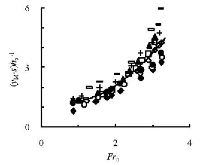
Fig.3 Variation of YM=(yM-s)/hoagainst Frofor different slit sizes

Fig.4 Variation of XM=xM/hoagainst Frofor different slit sizes
Figures 3 and 4 are the variations ofYM=(yM-s)/hoandXM=xM/hoagainstFrofor different slit sizes, respectively. The relative maximum elevationYMmainly depends onFro, whereas the effect of geometry is small for the different type M-STEDs. From Fig.3, we have

The coefficient of determination is 0.824 forMY. The relative distanceMX, however, is related to the geometries of the M-STEDs, as well as tooFr. The differences of MXfor the different geometries are significant, and the distance of the M-STED with2=a0 m is the largest, followed by that of the M-STED witha2=0.0175 m, that of the STED for the sameFrois the smallest, due to the effects of the outlet area on the flow. The large outlet area supports to the largeXM. Using the data of Fig.4, the best fits are
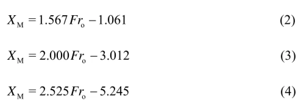
respectively, and the corresponding coefficients of regression are 0.921, 0.809 and 0.939 for the three type structures and experimental conditions mentioned above. Those results could be also seen from Fig.2.
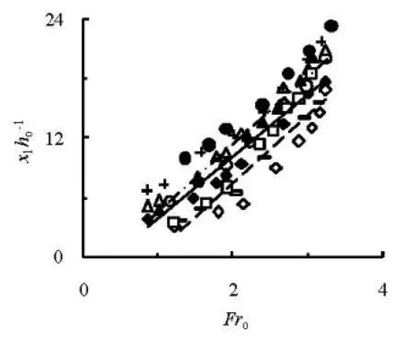
Fig.5 Variation of X1=x1/hoagainst Frofor different slitsizes

Fig.6 Variation of Xm=xm/hoagainst Frofor different slit sizes
Figures 5 and 6 are the variations ofX1=x1/hoandXm=xm/hoagainstFrofor different slit sizes, respectively. For the geometries with different slit sizes, the same trends can be seen for eitherX1orXm. In terms of the relative distances, the M-STED is the first witha2=0 m, followed by the M-STED witha2=0.0175 m, and the STED at the sameFro.It implies that increasing area of the outlet makes the jet flow go a larger distance. The case M24 with a large outlet area produces a larger distance than the case M14 or M00. Moreover, the slit number has also the effect with respect to this distance, and the case M24 with =n12 results in a larger distance than the case M21 with =n4 although they have the same area of the outlet. The relative distance1Xincreases withoFras

and the corresponding coefficients of regression are 0.900, 0.722, and 0.978, respectively. Similarly,mXcan be expressed as

and their coefficients of regression are 0.827, 0.738, and 0.988.
2.2Energy dissipation

Figures 7 and 8 show the variations ofηagainstFrofor different slit numbersnata2=0.0175 m and 0 m, respectively. Firstly, the energy dissipation ratioηincreases with the increasing approach flow Froude numberFrofor the M-STED of differentnora2. Secondly, the energy dissipater withn=12 has a largerηthan the one withn=4. Lastly, there are slight differences for different slit sizes whena2≤0.0175 m. It could be concluded that, from the results of Figs.7 and 8, it is the slit numbernthat directly causes the effects of the energy dissipation.

Fig.7 Variation of η againstoFr for different slit numbers n at2=a0.0175 m
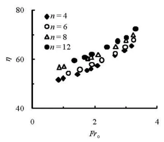
Fig.8 Variation of η againstoFr for different slit numbers n at2=a0 m
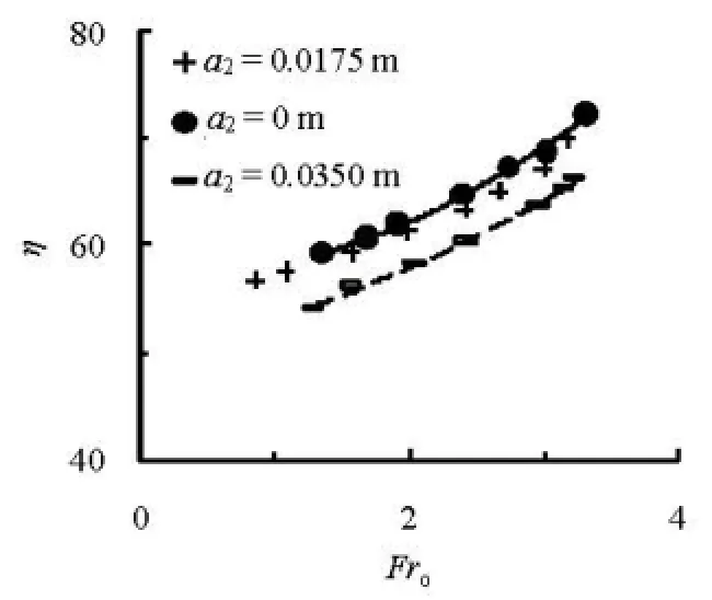
Fig.9 Comparison of η between multiple slits (=12)n and single slit
Figure 9 is the comparison ofηbetween the energy dissipaters with the multiple slits (=12)nand the single slit. It could be clearly seen that, the MSTED with2=a0 m has a slightly larger energy dissipation than one with2=a0.0175 m, and as compared to the conventional STED, the energy dissipation ratio of the M-STED presented in this study is increased significantly. For cases M24 and M00 (listed in Table 1), the best fits are
respectively, according to the data of Fig.9, and in Eqs.(11) and (12), subscripts M24 and M00 stand for the case names (see Table 1). Those two equations are valid under the conditions of this study. Meanwhile, the effects ofut>0 on the energy dissipation are not considered because relative comparisons are only conducted in the present work.
Furthermore, it could be noticed that, those two lines expressed by Eqs.(11) and (12) have approximately the same interval at the differentFro, and the increments are 4.34% forFro=2.0 and 4.84% forFro=3.0, respectively, which means that the MSTED remarkably enhances the energy dissipation ratioηcomparing with the conventional STED.
2.3Cavitation characteristics
The vacuum model experiments were conducted in a vacuum tank in order to investigate the cavitation performance of the M-STED. The incipient cavitation numberiσfor each case is measured by means of the 8-channel cavitation noise measurement instrument (TST-1202). The measurement system consists of a hydrophone, an amplifier and filter, a collector and a computer[19].
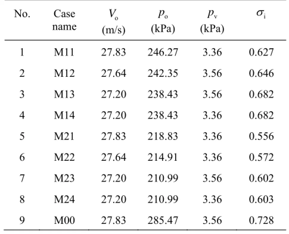
Table 2 Incipient cavitation numbers
The background noise of the flow is measured when the water head is low, and 0.25 m-head is chosen in this study. It is reasonable that the noise is considered as the background because there is no cavitation of the flow in this situation. The flow noise is measured in the interval of 0.20 m water head increment. The incipient cavitation occurs and is determined when the measured noise of the flow is about 10 dB larger than the background noise, and the working head is recorded as the critical condition of the occurrence of cavitation.
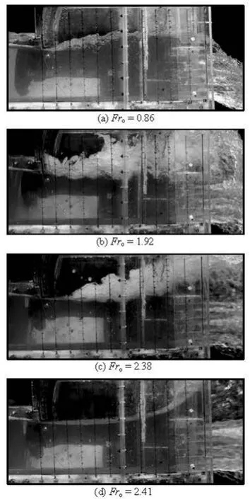
Fig.10 Process of flow choking (M12)
Table 2 is the data of the incipient cavitation numberiσfor all the cases, in which iσis expressed as
whereopand oVare the pressure and the velocity in the measured section, located at 0.15 m before the reduction section of the M-STED,vpis the saturated steam pressure at the measured temperature of the water, and =ρ1 000 kg/m3, is the density of the water. It could be noticed that, from Table 2, the series of cases M2i(=1-4)ihas the minimum incipient cavitation numbers among those three sets of models,while the values of the conventional STED, such as M00, is the biggest. In fact, those results are produced because the pressureopof cases M2iin the measured section is the least due to the existence of multiple slits. Meanwhile, the slit number induces a slight increase of the incipient cavitation number for the same set of model.
2.4Flow choking
In a supercritical chute flow, any obstructions may cause a flow breakdown[20]. The M-STEDs are, therefore, specially studied in this regard. Figure 10 demonstrates the whole process of the flow choking (M12), and a typical process includes four states, i.e., the appearance, the formation, the development and the disappearance (see Figs.10 (a) to 10(d)). Here, the second state, namely, the formation, is defined as the flow choking for the M-STED, and in this state, the recirculation just reaches the pressure flow edge and fills the surface on the flow.
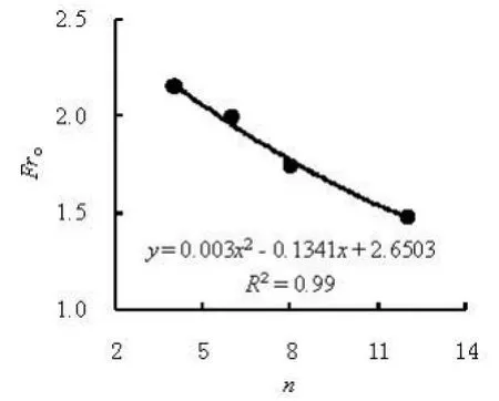
Fig.11 Variation of Froagainst n at2=a0.0175 m for flow choking
The experimental observations show that the flow choking is dominated by the structural forms, as well as the approach Froude numberFro, and there are three results from the present study. For the first set of cases, i.e., each of M11-M14, there are all four states of the flow choking of the appearance, the formation, the development and the disappearance. Figure 11 is the variation of the choking Froude numberFroagainst the slit numbernat2=a0.0175. Clearly,Frodecreases with the increase ofn, which means that the slit number tends to reduce the choking Froude number.
For cases M21-M24, there are no phenomena of the flow choking, which may be related to the slit size of the M-STED. The flow can pass smoothly through the M-STED when2ais small or equal to zero so that the flow choking would disappear.
For a kind of absolute geometry, i.e., the case M00, there is one slit in the outlet. Table 3 is the comparison of the flow choking Froude number for cases M14 and M00, in which subscripts 1, 2, 3, and 4 of the Froude number stand for the four states of the appearance, the formation, the development and the disappearance, respectively. It is noticed that in all cases listed in Table 3, the choking Froude number of the case M14 is significantly less than that of the case M00. It demonstrates that the multiple slits can decrease the choking Froude number and even eliminate the phenomena of the flow choking, like the cases M21-M24.
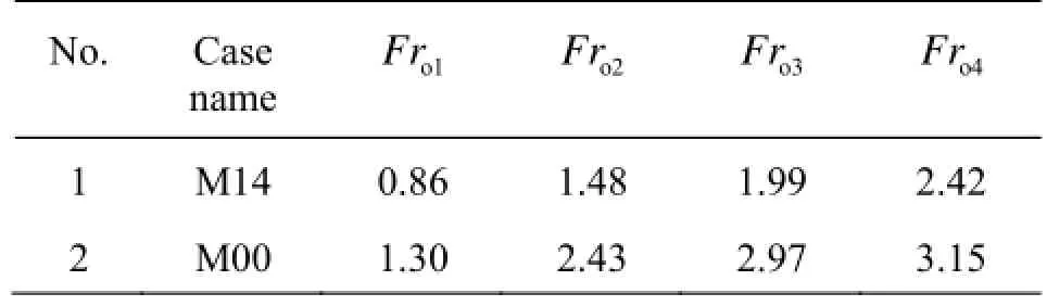
Table 3 Comparison of flow choking Froude number
3. Conclusion
In this study, a multiple slit-type energy dissipater is developed, and the hydraulic characteristics, including the flow regime, the jet flow trajectory, the energy dissipation, the cavitation characteristics, and the flow choking, are experimentally investigated by means of three sets of physical models in nine cases. The results show that the energy dissipater presented in this study enjoys a suitable hydraulic performance, and the energy dissipation ratio is increased by about 5% comparing with the conventional slit-type energy dissipaters thanks to the effects of the turbulence and the friction between the different layers of the jet flow and the increased air entrainment.
[1] LIAN J. J., YANG M. Hydrodynamics for high dam[M]. Beijing, China: China Water Power Press, 2008(in Chinese).
[2] VISCHER D. L., HAGER W. H. Energy dissipators[M]. Rotterdam: A. A. Balkema, 1995.
[3] DENG Jun, XU Wei-lin and ZHANG Jian-min et al. A new layout of stilling basin-horizontal multiple submerged jets[J]. Science in China Series E-Technological Sciences, 2009, 39(1): 29-38(in Chinese).
[4] JUON R., HAGER W. H. Flip bucket without and with deflectors[J]. Journal of Hydraulic Engineering, ASCE, 2000, 126(11): 837-845.
[5] SCHMOCHER L., PFISTER M. and HAGER W. H. et al. Aeration characteristics of ski jump jets[J]. Journal of Hydraulic Engineering, ASCE, 2008, 134(1): 90-97.
[6] SAVIC L., KUZMANOVIC V. and MILOVANOVIC B. Ski jump design[J]. Water Management, 2010, 163(10): 523-527.
[7] PAGLIARA S., AMIDEI M. and HAGER W. H. Hydraulics of 3D plunge pool scour[J]. Journal of Hydraulic Engineering, ASCE, 2008, 134(9): 1275-1284.
[8] STEINER R., HELLER V. and HAGER W. H. et al. Deflector ski jump hydraulics[J]. Journal of HydraulicEngineering, ASCE, 2008, 134(5): 562-571.
[9] LUCAS J., HAGER W. H. and BOES R. M. Deflector effect on chute flow[J]. Journal of Hydraulic Engineering, ASCE, 2013, 139(4): 444-449.
[10] HUANG Qiu-jun, WU Jian-hua. Research on contraction energy dissipaters[J]. Journal of Hohai University (Natural Sciences), 2008, 36(2): 219-223(in Chinese).
[11] LI Gui-fen, LIU Qing-chao. Numerical computation of slit-type supercritical flows[J]. Journal of Hydroelectric Engineering, 1990, (1): 7-15(in Chinese).
[12] ZHANG Yan-fa, WU Wen-ping. Experimental researches on the flow profile and the nappe trajectory distance for slit-type bucket[J]. Journal of Hydraulic Engineering, 1989, 20(5): 14-21(in Chinese).
[13] YANG S. L. Discussion of the hydraulic calculation method of flow from contraction type flip bucket of high dam[J]. Water Power, 1989, (7): 48-51(in Chinese).
[14] LIU Ya-kun, NI Han-gen. Abrupt deflected supercritical water flow in sloped channels[J]. Journal of Hydrodynamics, 2006, 20(3): 293-298.
[15] LIU Shi-he, QU Bo. Experimental investigation on the section configuration of jumping nappe[J]. Engineering Journal of Wuhan University (Eigineering Edition), 2004, 37(5): 1-4(in Chinese).
[16] WU Jian-hua, MA Fei and YAO Li. Hydraulic characteristics of slit-type energy dissipaters[J]. Journal of Hydrodynamics, 2012, 24(6): 883-887.
[17] PUTTON V. C., MARSON C. and FIOROTTO V. et al. Supercritical flow over a dentated sill[J]. Journal of Hydraulic Engineering, ASCE, 2009, 135(9): 1019-1026.
[18] CHAUDHRY M. H. Open-channel flow[M]. Englewood Cliffs, New Jersey: Prentice Hall, 1993.
[19] WU Jian-hua, WU Wei-wei and RUAN Shi-ping. On necessity of placing an aerator in the bottom discharge tunnel at the Longtan Hydropower Station[J]. Journal of Hydrodynamics, 2006, 18(6): 698-701.
[20] STEINER R., HELLER V. and HAGER W. H. et al. Deflector ski jump hydraulics[J]. Journal of Hydraulic Engineering, ASCE, 2008, 134(5): 562-571.
10.1016/S1001-6058(14)60010-X
* Project supported by the National Natural Science Foundation of China (Grant No. 51179056).
Biography: WU Jian-hua (1958-), Male, Ph. D., Professor
WU Jian-hua,
E-mail: jhwu@hhu.edu.cn
猜你喜欢
Chinese Physics B(2022年9期)2022-09-24
体育教学(2022年4期)2022-05-05
故事作文·低年级(2022年1期)2022-02-03
故事作文·低年级(2018年11期)2018-11-19
水动力学研究与进展 B辑(2018年5期)2018-10-27
故事作文·低年级(2018年9期)2018-09-17
故事作文·低年级(2018年6期)2018-07-04
水动力学研究与进展 B辑(2018年2期)2018-05-14
水动力学研究与进展 B辑(2017年4期)2017-09-15
读写算·小学低年级(2017年4期)2017-04-15

- 水动力学研究与进展 B辑的其它文章
- Deepwater gas kick simulation with consideration of the gas hydrate phase transition*
- Estimation of discharge and its distribution in compound channels*
- Influences of soil hydraulic and mechanical parameters on land subsidence and ground fissures caused by groundwater exploitation*
- A hybrid DEM/CFD approach for solid-liquid flows*
- An ocean circulation model based on Eulerian forward-backward difference scheme and three-dimensional, primitive equations and its application in regional simulations*
- Scale analysis of turbulent channel flow with varying pressure gradient*