
Turbulent structure and bursting process in multi-bend meander channel*
2014-06-01 12:30LIUXiaoxie刘小谢BAIYuchuan白玉川
水动力学研究与进展 B辑 2014年2期
关键词:白玉
LIU Xiao-xie (刘小谢), BAI Yu-chuan (白玉川)
State Key Laboratory of Hydraulic Engineering Simulation and Safety and Institute for Sedimentation River and Coastal Engineering, Tianjin University, Tianjin 300072, China, E-mail: liuxiaoxie@tju.edu.cn
Turbulent structure and bursting process in multi-bend meander channel*
LIU Xiao-xie (刘小谢), BAI Yu-chuan (白玉川)
State Key Laboratory of Hydraulic Engineering Simulation and Safety and Institute for Sedimentation River and Coastal Engineering, Tianjin University, Tianjin 300072, China, E-mail: liuxiaoxie@tju.edu.cn
(Received November 21, 2012, Revised June 2, 2013)
The flow characteristics in a meander channel are fully three-dimensional. With the primary flow in the streamwise direction, the secondary flow in the transverse and vertical directions induced by the channel bends are significant in the analyses of the turbulent structure. Some of the analyses in the straight channel, for instance, the quadrant analysis for the bursting phenomena, are inadequate in investigating the meander channel, since the flow in the transverse direction is not taken into account. In order to reveal the flow characteristics in a multi-bend meander channel, especially, the bursting process, experiments are conducted in the present study. With the three-dimensional quadrant analysis, the influence of the transverse flow velocity during the bursting process could be correctly addressed. The analyses and discussions are presented in this paper.
turbulent characteristic, meander channel, mulit-bend, bursting phenomena, three-dimensional
Introduction
A meander river, as the most common type in the nature, has been researched for decades. The characteristics of the turbulent flow in a meander river is essential in investigating the sediment entrainment and deposition on the river bed, and hence the river morphology[1-5]. As shown in literature[6-11], the flow characteristics in a meander channel are different from those in a straight channel. For instance, beside the primary flow in the streamwise direction, there is a secondary flow across the section due to the channel meander. This secondary flow goes from the concave bank towards the convex bank near the water surface, and from the convex bank towards the concave bank near the channel bottom, leading to a circular flow at the cross section of the meander channel. Since the sediment concentration near the channel bottom is higher than those near the water surface, the sediments deposit on the convex bank and erode on the concave bank. Blanckaert and De Vriend[12]found that the circular flow across the section of a meander channel is mainly due to the centrifugal force. Bai et al.[13]performed a theoretical analysis for the meander channel with constant curvature and discussed the effect of channel bends on the flow stability. Therefore, the flow characteristics are three-dimensional in the meander channel. Nevertheless, some of the analyses for the straight channel as a two-dimensional region may not be adequate in investigating the characteristics in a meander channel.
The quadrant analysis of the bursting phenomena is one of the instances. The bursting process in the straight channel could be classified into four different types of events depending on the conditional statistics of the velocity fluctuations in streamwise and vertical directions. The quadrant analysis categorizes the bursting events into four quadrants as: Q1 the outward interaction (u'>0, w'>0), Q2 the ejection (u'<0, w'>0), Q3 the inward interaction (u'<0, w'<0) and Q4 the sweep (u'>0, w'<0). The study of the bursting process reveals the contribution of the fluctuating velocities to the Reynolds shear stress. However, the traditional quadrant analysis for the straight channel neglects the influence of the flow velocity in the transverse direction, which is significant in a meander channel. In order to study the bursting events in thevortex chamber, Keshavarzi and Gheisi[14]proposed a three-dimensional quadrant analysis to account for the effect induced by the flow in the transverse direction.
In view of this consideration, experiments are conducted in this paper, in order to investigate the flow characteristics and the bursting phenomena in a meander mulit-bend channel using the three-dimensional quadrant analysis.
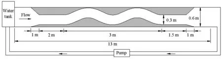
Fig.1 Schematic diagram of experimental flume (not on right scale)
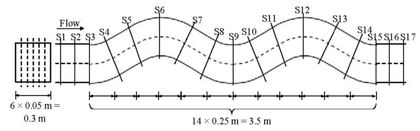
Fig.2 Layout of measuring cross section
1. Experimental setup and procedure
The experiments are conducted inside a re-circulating flume of 13 m in length, 0.6 m in width and 0.6 m in depth. The flume is re-shaped by using a perspex frame to construct a multi-bend meander channel of 0.3 m in width. The schematic diagram of the experimental flume is shown in Fig.1. The meander section is 3 m long, consisting of two identical generated sine curves with sinuosity is 1.05. The entrance and the exit of the meander section are connected with a 1.5 m long straight section and a 1 m transition section, respectively. The re-circulating flow in the flume is generated by the water pump and monitored with a valve. The experiments are performed without any bed sediment, i.e., under a smooth bed condition.
The instantaneous velocities of the flow are measured by using a three-dimensional acoustic Doppler velocity (ADV) meter with a sampling rate of 50 Hz. The ADV is a single-point downward facing Doppler velocity meter designed for laboratory and field applications with simple operation and without need of periodic recalibrations. Since the sampling volume is located at 0.05 m below the acoustic transmitter, there is no disturbance due to the probe. The locations of the measuring cross sections are shown in Fig.2. The test section includes the entire meander section and two straight sections of 0.5 m in length. There are seventeen measuring cross sections, each of which contains five vertical lines of 0.05 m in interval. The data are collected for every 0.01 m in water depth. At each measuring point, the duration of sampling is 60 s and 3 000 readings of velocity data in each direction are stored in a computer. The x-direction of the ADV is adjusted to point along the longitudinal direction of the channel; therefore, the instantaneous velocity in the streamwise, transverse and vertical directions could be measured.
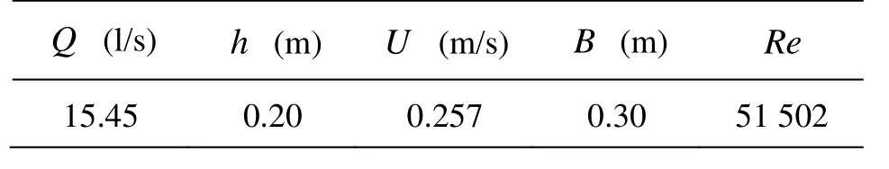
Table 1 Flow conditions of experimental tests
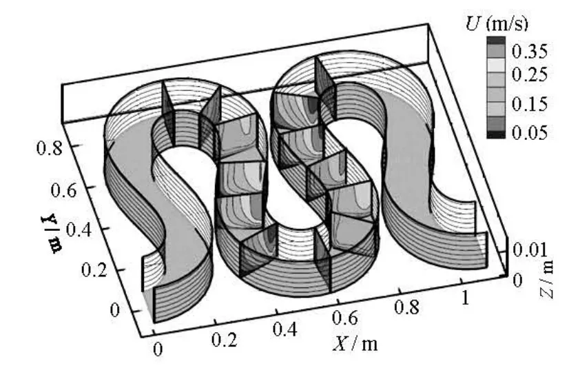
Fig.3 Distributions of streamwise velocity in Xu’s results[15]
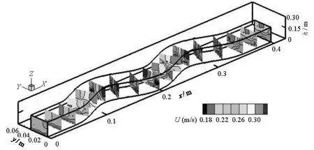
Fig.4 Distributions of streamwise velocity in the present study

Fig.5 Primary velocity field(water depth = 0.01 m)
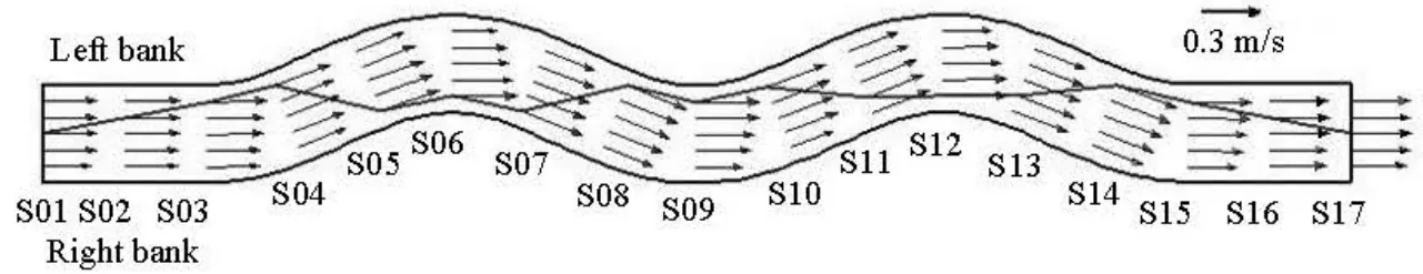
Fig.6 Primary velocity field(water depth = 0.15 m)
The water depth in the channel is controlled to be 0.2 m during experiments. Table 1 shows the hydraulic conditions of the flow in the tests, in which Q is the flow discharge, h is the water depth, U is the flow velocity, B is the channel width, Re is the Reynolds number of the flow, Re=Uh/ v, and v is the kinematic viscosity. Since the Reynolds number is about 50 000 in the straight channel section, the flow is in a fully turbulent regime according to the publicshed results of Bai et al.[13].
2. Experimental results and discussions
2.1 Flow velocities
The velocities measured using the ADV are the instantaneous velocities of the flow in streamwise, transverse and vertical directions, denoted as u, v and w, respectively. The time averaged velocities within the measuring duration could be computed as follows
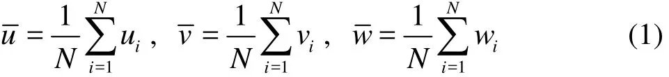
In order to verify the validity of the results measured in the present experiments, the published numerical results of Xu[15]are used for comparison. Xu[15]numerically simulated the flow velocity fields in a channel with sinuosity is 0.02 m and 0.15 m in width and 0.15 m in depth. The numerical results are shown in Fig.3. Meanwhile, the distributions of the primary flow, i.e., the streamwise velocity, at each measuring cross section along the channel in the present study are shown in Fig.4. The comparison between Figs.3 and 4 shows that the trend of the distribution of the streamwise velocity is very similar. The streamwise velocity reaches the maximum value at the apex of the convex bank and the minimum value at the apex of the concave bank. At the cross section of the apex of the channel bend, the streamwise velocity decreasesdiagonally from the water surface of the convex bank to the bottom of the concave bank. It may be inferred from this simple comparison that the measurements in the present study agree well with the published results and is acceptable for the following analyses.
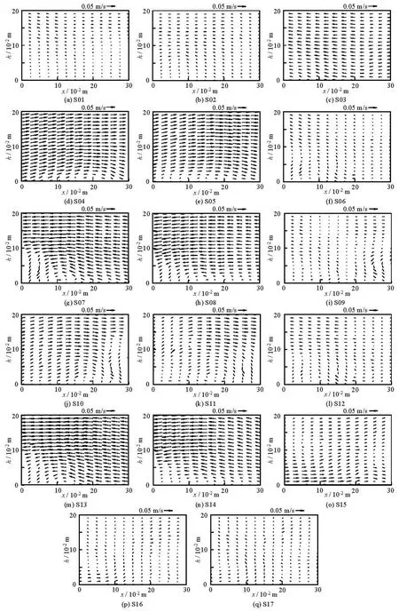
Fig.7 Secondary flow at each section
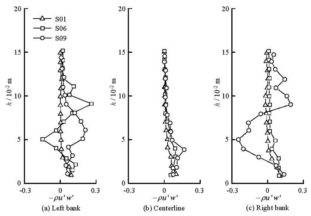
Fig.8 Vertical distribution of streamwise Reynolds shear stress
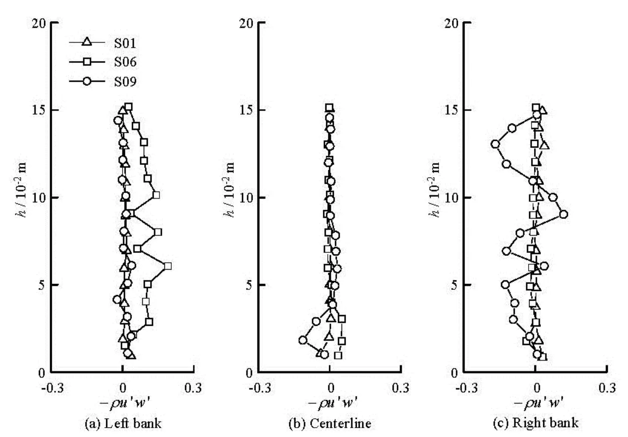
Fig.9 Vertical distribution of transverse Reynolds shear stress
The flow velocity fields of the primary flow or the streamwise velocity at the water depth is 0.01 m (near the maximum ejection height) and 0.15 m (near the peak point of the maximum velocity) are shown in Figs.5 and 6, respectively. The solid line in the figures represents the track of the maximum velocity across the section, which is also known as the main streamline. As shown in the figures, the distribution of the streamwise velocity is nearly uniform at the entrance straight channel. After the flow enters the meander section, the effect of channel bend makes the maximum velocity shifts from the location near the center of the channel to the convex bank. Since the experimental flume used is a multi-bend channel, the main streamline then shifts between the left bank and the right bank alternately along the channel. When the flow exits the meander section, the distribution of the streamwise velocity becomes uniform again, similar to those at the entrance.
The channel bends induce the secondary flow at the cross section, i.e., the flow in the transverse and vertical directions. The secondary flow at each cross section along the test section is shown in Fig.7. The horizontal axis represents the channel width, whereas the vertical axis is the water depth, i.e., 0.2 m for the present study. It is observed that the water surface elevation is different across the section, which is higher at the concave bank and lower at the convex bank. However, this elevation difference is only about0.002 m in the experiments of the present study, therefore, the vertical axis or the water depth is fixed at 0.2 m in the graph plotting in this paper.
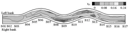
Fig.10 Normalized Reynolds shear stress in streamwise direction
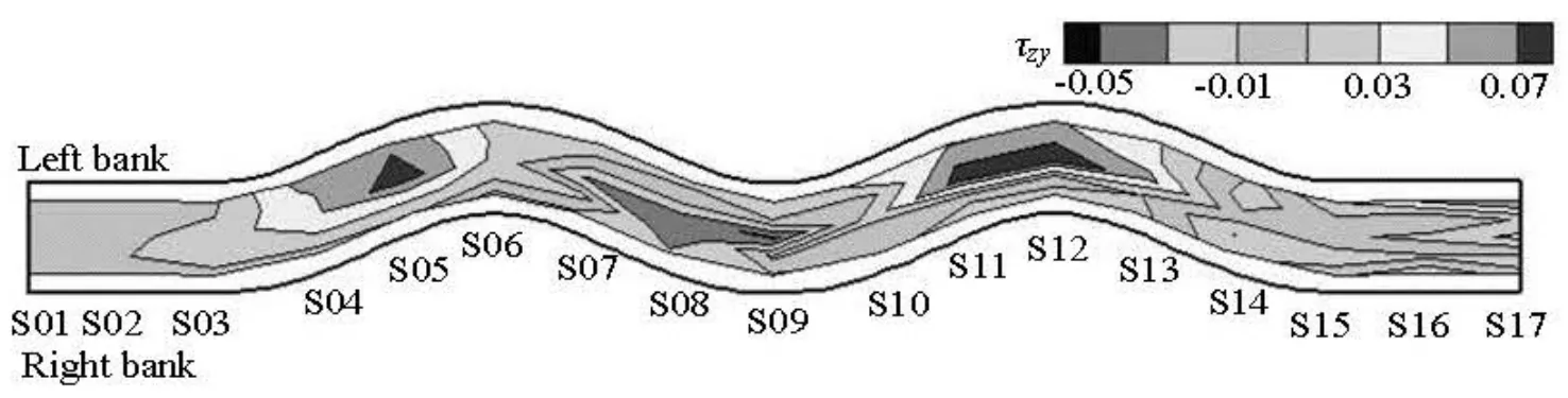
Fig.11 Normalized Reynolds shear stress in transverse direction
As shown in Fig.7, the intensity of the secondary flow within the straight channel is quite small comparing with those in the meandering section. In the meandering channel, the sections between the apexes of the bends are called the transition meander sections. As the convex and concave banks are located alternately along the channel, the direction of the secondary flow in the transition meander sections also follows this trend. Although the circular flow at each cross section of the transition meander channel is not apparent, the sign of the circular flow could also be found near the bottom of the channel. Hence, the clockwise and counterclockwise circular flows appear alternately along the meander channel. The intensity of the secondary flow at the apex of the bends is also quite low comparing with those at the transition meander section. This is because the direction of the circular flow induced by the previous bend is opposite to that induced by the current bend, leading to the cancellation of the flow velocities.
2.2 Reynolds shear stress
When the water flows through the channel bed, the Reynolds shear stress is induced. The investigation on the Reynolds shear stress near the bed helps a better understanding of the interaction between the flow and the channel bed, and hence the sediment motion if it is present. As long as the velocity fluctuations are known, the Reynolds shear stress near the bottom can be calculated. The velocity fluctuation is the difference between the instantaneous velocity and the timeaveraged velocity as shown below

where u', v' and w' is the velocity fluctuation in the streamwise, transverse and vertical directions, respectively. According to the Reynolds-averaged Navier-Stokes equations (RANS equations), the Reynolds shear stresses in the streamwise and transverse directions can be computed as τzx=' and τzy=, respectively.
The Reynolds shear stresses in the streamwise and transverse directions for sections S01, S06 and S09 are taken as the representatives to analyze the vertical distribution. These sections are chosen because section S01 represents the undisturbed flow conditions in the straight channel, and sections S06 and S09 are at the apex of the meandering bends where the concave bank and the convex bank are on the left bank of the channel, respectively. The vertical distributions of the Reynolds shear stresses in the streamwise and transverse directions along the water depth at the left bank, the centerline and the right bank, i.e., the measuring lines #5, #3 and # 1, are shown in Figs.8 and 9, respectively. It is noted from the figures that the value of the transverse Reynolds shear stress is much less than that of the streamwise Reyholds shear stress, showing that the Reynolds shear stress in the streamwise direction is dominant in the meander channel. In addition, the figures also show that the vertical distributions of the Reynolds shear stress in the straight channel are almost uniform across the whole section, with higher value near the bottom quickly decreasing towards the water surface direction to about zero value. For the sections at the apex of the meandering bends, the vertical distributions at the centerline and the convex bank are very similar to those at the straight section and do not vary too much. However, the variations at the concave bank at both sections S06 and S09 are more violent. For the Reynolds shear stress in the streamwise direction, the vertical distributions of S06 and S09 at the concave bank vary in a similar trend,decreasing to a negative value and then increasing to a positive value from the bottom to the water surface. In contrast, the vertical variations of the transverse Reynolds shear stress of S06 and S09 are in the opposition directions. This is due to the alternately shifting of the concave bank in the multi-bend meandering channel. In fact, the transverse Reynolds shear stresses at S06 and S09 are both vertically deflected from the concave bank to the convex bank.
Since the sediment transport behavior appears almost near the bottom, the study is focused on the Reynolds shear stress at 0.01 m above the bed (the maximum ejection height). The computed Reynolds shear stresses in the streamwise and transverse directions are shown in Figs.10 and 11, respectively. Only the data in the measuring area are shown in the figures, therefore, there is a 0.05 m gap between the plotted results and the channel wall.
As shown in Fig.10, the distribution of the streamwise Reynolds shear stress in the straight channel is more even compared with that in the meandering channel. In addition, within the meander sections, the streamwise Reynolds stress is higher near the concave side but lower near the convex side. It can also be seen that there is a sudden reduction in the streamwise Reynolds stress near the concave bank after the apex of the bend. On the other hand, Fig.11 shows the Reynolds shear stress distribution in the transverse direction. The magnitude of the transverse Reynolds stress is generally less than that of the streamwise Reynolds stress but they are in the same order of magnitude. Moreover, the distribution of the transverse Reynolds stress has a similar trend with that of the streamwise Reynolds stress, i.e., higher at the concave bank but smaller at the convex bank. Furthermore, the transverse Reynolds stresses at the concave bank on the right hand side of the channel are negative, whereas those on the left bank are positive. This is due to the direction definition of the transverse axis. Since the transverse Reynolds stress points from the concave bank toward the convex bank. the direction of the transverse Reynolds stress on the right channel bank is opposite to the axis and becomes negative in value.
Therefore, one may infer from above experimental results that if there is sediment on the bottom, the sediment erosion occurs at the concave bank while the sedimentation can be observed at the convex side for a single channel bend. For the multi-bend channel, the sediment deposition and entrainment should occur alternately along one side of the channel bank. This inference is in agreement with the published results[16].
2.3 Bursting process in meander channel
2.3.1 Classification of three-dimensional bursting events
As discussed in previous sections, the secondary flow and the transverse Reynolds shear stress are important characteristics of the turbulent flow in the meandering channel. Hence, the velocity and the velocity fluctuation in the transverse direction (v and v') could not be ignored during the investigation of the meander flow characteristics. However, the traditional two-dimensional quadrant analysis for investigating the bursting phenomena in the straight channel considers only the streamwise and vertical velocity fluctuations, which may not be adequate for the meander channel. Keshavarzi and Gheisi[14]proposed a threedimensional quadrant analysis for the bursting process to account for the traverse terms induced by the channel bends. Since their experiments were performed in a vortex chamber, they classified the bursting events into the internal group (towards the center of chamber) and the external group (towards the outer wall). However, this classification could not be applied in the present study, since the inner and outer banks appear alternately in the multi-bend channel. Therefore, similar to the way of Keshavarzi and Gheisi[14], the bursting process in the multi-bend channel of the present study is also categorized into two groups. Class A represents the events deflecting towards the right bank of the channel, while Class B signifies the events which deflect towards the left bank. The bursting phenomena, which consist of four events in the rightward group and four events in the leftward group, could be defined depending on the sign of the fluctuating velocities as follows:
(1) Zone 1: Class A-1 or the rightward outward interaction (u'>0, v'>0, w'>0).
(2) Zone 2: Class A-2 or the rightward ejection (u'<0, v'<0, w'>0).
(3) Zone 3: Class A-3 or the rightward inward interaction (u'<0, v'<0, w'<0).
(4) Zone 4: Class A-4 or the rightward sweep (u'>0, v'>0, w'<0).
(5) Zone 5: Class B-1 or the leftward outward interaction (u'>0, v'<0, w'>0).
(6) Zone 6: Class B-2 or the leftward ejection (u'<0, v'>0, w'>0).
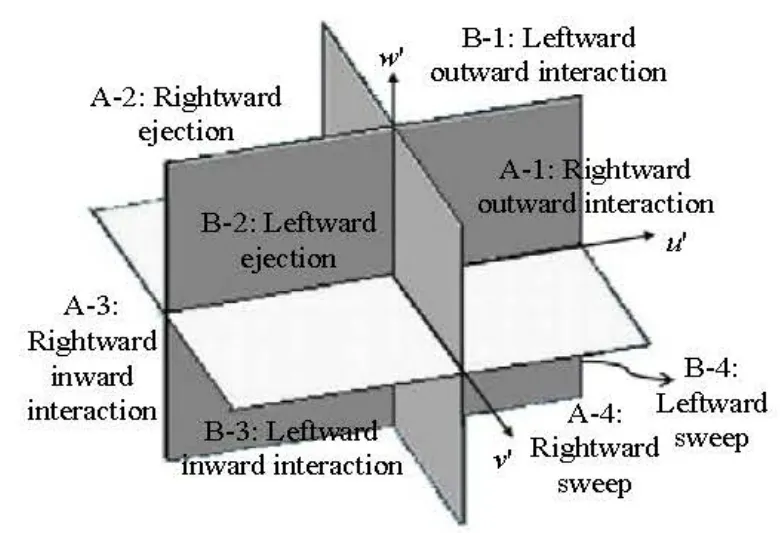
Fig.12 Three-dimensional view of eight classes of bursting events

Fig.13 Contribution probabilities of eight bursting events
(7) Zone 7: Class B-3 or the leftward inward interaction (u'<0, v'>0, w'<0)
(8) Zone 8: Class B-4 or the leftward sweep (u'>0, v'<0, w'<0)
The classification of the three-dimensional bursting events is also graphically shown in Fig.12. These eight classes of the bursting process indicate the momentum transfer between the horizontal adjacent water flow layers, which cause the instantaneous turbulent shear stress along the streamwise and transverse directions.
2.3.2 Contribution probability of bursting events
By counting the occurrences of eight zones of the bursting events, the contribution probability of each event could be obtained as follows:
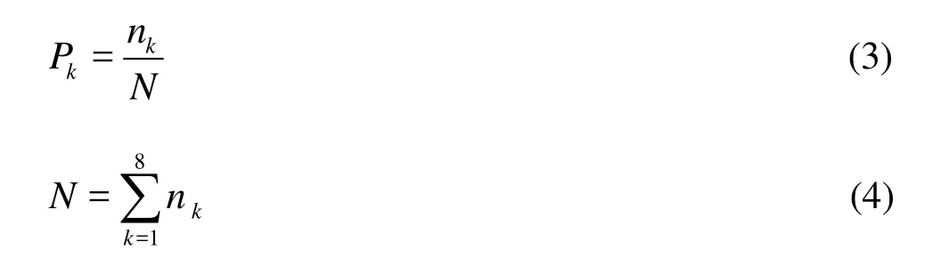
where P is the contribution probability or the frequency of each event, nkis the number of occurrencea of each event, and N is the total number of events which is also equal to the number of the instantaneous velocity samples. The subscript represents the individual class zone (k=1-8). Since the bursting process indicates the momentum transfers between the water layer and the channel bed, the data measured at a distance of 0.01 m from the bed, which is the maximum ejection height, are selected as the representatives. The distributions of the contribution probabilities of eight zones of events are shown in Fig.13. It is shown that the contribution probability of the events in bursting classes of the rightward ejection (A-2), the rightward sweep (A-4), the leftward ejection (B-2) and the leftward sweep (B-4) is greater than that of other classes. In addition, the front sides of the channel bends are dominated by the rightward classes, whereas the back sides are governed by the leftward classes. In another words, the bursting process in the meander channel is always from the concave bank towards the convex bank. Hence, if there is sediment on the bottom of the channel, the influence of the rightward and leftward groups of events will cause the sediment deposited on the concave bank and entrained on the concave bank, leading to an alternate appearance of sedimentation and erosion along the meander channel.
3. Conclusions
Experiments are conducted in the present study to investigate the flow characteristics in the multibend meander channel. The conclusions are as follows:
(1) The flow in the streamwise direction is the primary flow in the meander channel, which is higher near the convex bank and smaller near the concave bank. As a result, the main streamline shifts between the left bank and the right bank alternately along the channel. Similarly, the direction of the secondary flow, which consists of the transverse and vertical flows, in the transition meander sections also follows this trend.
(2) The Reynolds shear stresses in the streamwise and transverse directions are higher on the concave bank and lower on the convex bank.
(3) The three-dimensional quadrant analysis is applied to investigate the bursting phenomena in the multi-bend channel. It is shown that the contribution probability of the classes of the rightward ejection, the rightward sweep, the leftward ejection and the leftward sweep is greater than that of other classes. The front sides of the channel bends are dominated by the rightward classes, whereas the back sides are governed by the leftward classes.
References
[1] JULIEN P. Y.River mechanics[M]. Cambridge, UK: Cambridge University Press, 2002.
[2] SHAO Xue-jun, WANG Guang-qian. The impact of upper yellow river hydropower develoment on downstream fluvial processes[J].Journal of HydroelectricEngineering,2002, (E01): 128-138(in Chinese).
[3] HU Chun-hong, GUO Qing-chao. Mathematical model and dynamic equilibrium threshold on sediment at lower Yellow River[J].Science in China Series E: Technological Sciences,2004, 34(A01): 133-143(in Chinese).
[4] SHAO Xue-jun, WANG Xing-kui.Introduction to river mechanics[M]. Beijing, China: Tsinghua Univer- sity Press, 2005(in Chinese).
[5] ZHANG Rui-jing, XIE Jian-heng and CHEN Wen-biao.River mechanics[M]. Wuhan, China: Wuhan Universi- ty Press, 2007(in Chinese).
[6] DUAN J. G., JULIEN P. Y. Numerical simulation of the inception of channel meandering[J].Earth SurfaceProcesses and Landforms,2005, 30(9): 1093-1110.
[7] CHEN D., DUAN J. D. Simulating sine-generated meandering channel evolution with an analytical model[J].Journal of Hydraulic Research,2006, 44(3): 363-373.
[8] DUAN J. G., JULIEN P. Y. Numerical simulation of meandering evolution[J].Journal of Hydrology,2010, 391(1-2): 34-46.
[9] XU Dong, LIU Zhao-ping and QIAN Ai-guo et al. Three-dimensional numerical simulation of flow in river bends[J].Journal of Hydraulic Engineering,2010, 41(12): 1423-1431(in Chinese).
[10] BAI Yu-chuan, YANG Yan-hua. The dynamic stability of the flow in meander channel[J],Science China Te-chnological Science,2011, 54(4): 931-940.
[11] LIU Xiao-xie, BAI Yu-chuan. Three dimensional bursting phenomena in meander channel[J].Transactionsof Tianjin University,2013, 19(1): 17-24.
[12] BLANCKAERT K., De VRIEND H. J. Secondary flow in sharp open-channel bends[J].Journal of Fluid Me-chanics,2004, 498: 353-380.
[13] BAI Yu-chuan, JI Zi-qing and LIU Xiao-xie et al. Instability of laminar flow in narrow and deep meander channel with constant curvature[J].Scientia Sinica, Physica, Mechanica and Astronomica,2012, 42(2): 162-171(in Chinese).
[14] KESHAVARZI A. R., GHEISI A. R. Stochastic nature of three dimensional bursting events and sediment entrainment in vortex chamber[J].Stochastic Environmental Research and Risk Assessment,2006, 21(1): 75-87.
[15] XU Dong. A study on the dynamic process of meandering rivers[D]. Doctoral Thesis, Tianjing, China: Tianjin University, 2008(in Chinese).
[16] ESFAHANI F. S., KESHAVARZI A. Effect of different meander curvatures on spatial variation of coherent turbulent flow structure inside ingoing multi-bend river meanders[J].Stochastic Environmental Research and Risk Assessment,2011, 25(7): 913-928.
10.1016/S1001-6058(14)60023-8
* Project supported by the National Natural Science Foundation of China for innovative rese arch groups of China (Grant No. 51021004), the National Natural Science Foundation of China (Grant Nos. 51279124, 50809045).
Biography: LIU Xiao-xie (1982-), Female, Ph. D.
BAI Yu-chuan, Email: ychbai@tju.edu.cn
猜你喜欢
青年文学家(2022年10期)2022-04-25
石材(2020年10期)2021-01-08
扬子江诗刊(2020年6期)2020-11-17
扬子江(2020年6期)2020-11-16
紫禁城(2020年1期)2020-08-13
作文与考试·小学高年级版(2018年9期)2018-07-02
宝藏(2018年1期)2018-04-18
艺术品鉴(2017年10期)2017-09-08
青春岁月(2016年21期)2016-12-20
校园英语·上旬(2016年9期)2016-05-14

- 水动力学研究与进展 B辑的其它文章
- Numerical prediction of 3-D periodic flow unsteadiness in a centrifugal pump under part-load condition*
- Experimental investigations of transient pressure variations in a high head model Francis turbine during start-up and shutdown*
- Improved conservative level set method for free surface flow simulation*
- Capillary effect on the sloshing of a fluid in a rectangular tank submitted to sinusoidal vertical dynamical excitation*
- Effect of compressive stress on the dispersion relation of the flexural–gravity waves in a two-layer fluid with a uniform current*
- Comprehensive analysis on the sediment siltation in the upper reach of the deepwater navigation channel in the Yangtze Estuary*