
Approaches and development of the modeling of the spiral bevel and hypoid gear*
2014-07-31 20:22XiaohongMIXieeryazidanAdayiHanDING
机床与液压 2014年2期
Xiao-hong MI, Xieeryazidan·Adayi, Han DING
School of Mechanical Engineering, Xinjiang University, Urumqi 833046, China
Approaches and development of the modeling of the spiral bevel and hypoid gear*
Xiao-hong MI†, Xieeryazidan·Adayi, Han DING
SchoolofMechanicalEngineering,XinjiangUniversity,Urumqi833046,China
Accurate modeling of spiral bevel and hypoid gear is the foundation of the tooth contact analysis (TCA) technology and error correction technology of the tooth surface, which is the key technology in digitized manufacturing. This paper summarized the related achievements and divided the methods of modeling spiral bevel and hypoid gear into three categories, including modeling by discrete points on the tooth surface, curve fitting, and simulation machining, and generalized the main steps and the key ideas of each method. At the same time, this paper analyzed the problems and inadequacies existing in the process of model design. Three directions were proposed for modeling of spiral bevel and hypoid gear in the future, that are more accuracy, more efficiency and more flexibility. The paper provides some methods that make the design and machining of spiral bevel and hypoid gear faster and more accurately.
Accurate modeling, Spiral bevel and hypoid gear, Digitized manufacturing, Tooth contact analysis (TCA), Simulation machining
1.Introduction
Spiral bevel and hypoid gear are extensively used in the crossing or intersecting axis power transmission. Due to the high contact ratio, they have some excellent properties, such as the higher carrying capacity, the smooth transmission, the lower noise and so on[1-2]. Therefore, the design and manufacturing of spiral bevel and hypoid gear are still hot topics in research field. Spiral bevel and hypoid gear play a vital role in automobile helicopter, machine tool and other branches of industry[3-5] owing to their outstanding performances. The structure of the tooth surface is quite complex, and manufacturing precision and quality directly affect the transmission efficiency, noise, movement precision, service life of power machinery[6]. The full-featured Phoenix®IICNC milling machine with five-axis linkage independently developed by American Gleason Corporation, which is equipped with the most state-of-the-art Gleason expert manufacturing system(GEMS) for spiral bevel and hypoid gear, represents the highest level of digital manufacturing all over the world[7]. The tooth contact analysis (TCA) and correction of the deviation of tooth surface technologies based on the model of gear drives had been the core of the GEMS[8]. Recently researches on the spiral bevel and hypoid gear have become increasingly deep in the field of gear design and been working to digitized and diversified.
In this paper, the research achievements of modeling at home and abroad are analyzed from three aspects: ① the point-to-surface modeling by discrete points, the key step is to obtain and solve the discrete points on the tooth face[9-11]; ② the line-to-surface modeling by suturing curves, the core is the solution of tooth profile curve equation[12-15]; ③ modeling by the simulation machining based on virtual reality technology, the vital idea is to control the equivalent conversion and program control when the cutter and gear blank moving[16-20].
In addition, based on the related research, analyzing and summarizing the problems exist in the modeling and sum up the related solutions to these problems. In order to create a condition that contribute to design, analysis and machining accurately and efficiently, the trends of tooth surface modeling are discussed from three directions : ①requirements of tooth surface precision become higher; ②the efficiency of the modeling will be higher; ③modeling method will be more flexible.
2.Basic ideas of modeling of spiral bevel and hypoid gear
2.1.Meshing theory about spiral bevel and hypoid gear
The recent study on the modeling of tooth surface, either modeling by equations or by cutting processing is based on the meshing theory about spiral bevel and hypoid gear. It is also named principle of conjugated curved surfaces[21], which mainly consider the contact transmission between two motional curved surfaces. As shown in Figure 1, there is a pair of gear drives in engagement; in Figure 2, it presents the meshing theory about spiral bevel and hypoid gear. Two motional curved surfacesΣ1andΣ2are contact transmission and in tangency at the pointM, their common tangent plane isT. Additionally the pointO1andO2are their respective origin of the coordinate system fixedly connected. The vector of the pointMon the surfacesΣ1is described withr1, and its unit normal vector isn1.Likewise, the vector of the pointMon the surfacesΣ2is described withr2, and unit normal vector isn2.Thembecomes the vector from the pointO1to the pointO2. Then conjugate curved surfaces should be satisfied with the equations as follows[22]:
(1)
Above equations can be transformed by the relative differential method, as following equation[22]:
(2)
Where,v12is relative speed between the surfaces ∑1and ∑2. Formula (1) represents basic equations, and formula (2) represents meshing equation.

Figure 1. A pair of gear drives
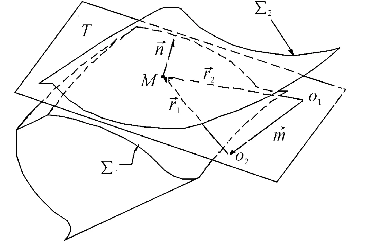
Figure 2.The meshing theory about spiral bevel and hypoid gear
2.2.Basic idea of modeling
Modeling of spiral bevel and hypoid gear is based on the meshing theory and machining approaches, by means of relative analysis software and drawing software. The basic idea is demonstrated in the Figure 3: taking advantage of the 3D mapping and data analysis software, it can complete general modeling process from point to surface, from the point to the line and then surface, from line to surface, or direct cutting simulation.
Researchers have provided us some bold attempts and innovations about the key step in the modeling process, including extracting the tooth surface data points, the point-to-line fitting, structuring from line to surface, and the application of virtual machining, finally all kinds of effective modeling methods were obtained.
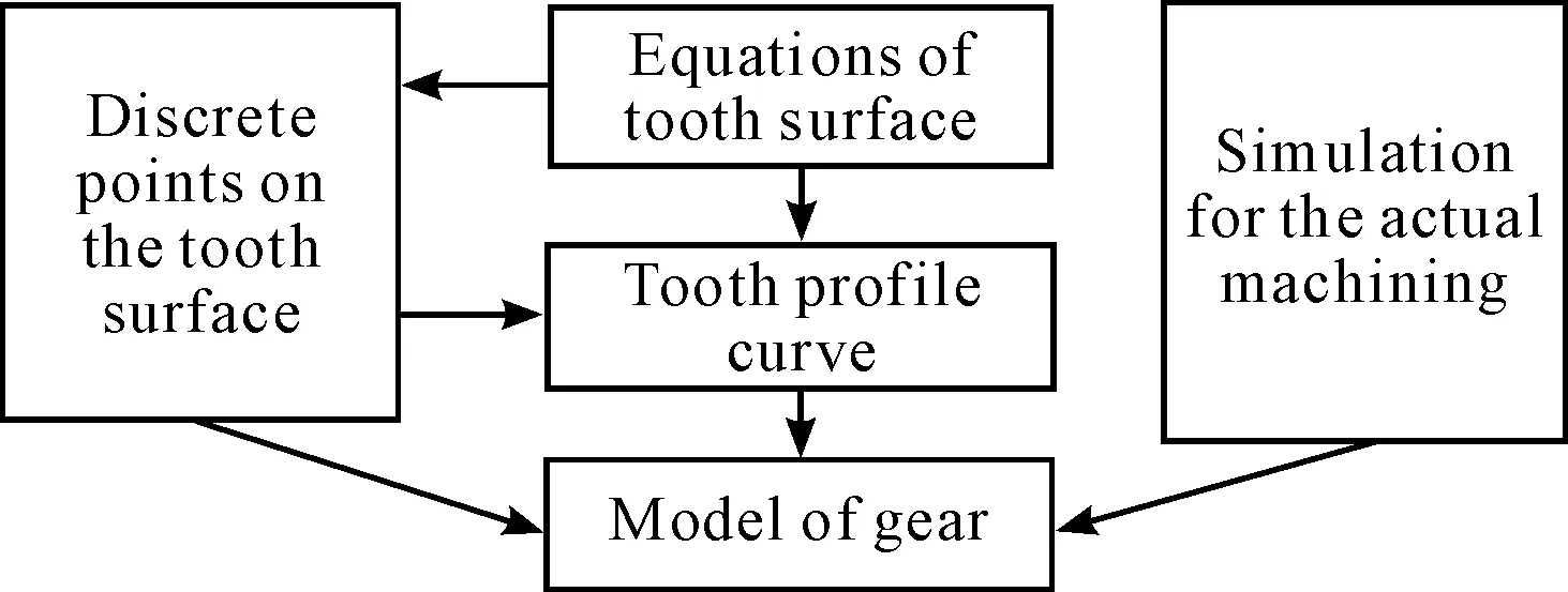
Figure 3. Basic idea of modeling
3.Methods of modeling of spiral bevel and hypoid gear
In the early days, in the light of tooth meshing theory, Professor Faydor L. Litvin had finished the design of tool shapes and motion conversion, then deduced the equations of tooth surface where the gear was enveloped and generated by tool paths[1-2]. Furthermore, the famous Korean scholar Suh had got rid of the traditional principle and methods, and made creative application of the spherical involutes curve theory in modeling of spiral bevel and hypoid gear, which put up with a new pathway of parametric modeling[5].
In China, the spiral bevel and hypoid gear drives play an irreplaceable position in the field of industry, and the government had been increasing investment and research on spiral bevel and hypoid gear. Many institutes such as State Key Laboratory of the Gear Transmission in Chongqing University, Central South University, Northwestern Polytechnic University, Zhengzhou Institute of Gear[8] have carried out related studies. Combining with the recent research literature about the spiral bevel and hypoid gear, this paper summarized the modeling of spiral bevel and hypoid gear from three aspects.
3.1.The point-to-surface modeling by discrete points
It is the traditional method that base on the generated equation of gear tooth surface derived by Professor Litvin. Firstly, the software (such as Matlab) is applied to solve the equations of tooth surface, which obtains information about discrete points equably distribute on the gear tooth surface (as shown in the Figure 4). Then, it is necessary to import the data of these discrete points into relevant 3D modeling software(Pro/E, CATIA, Solid Works, etc). Finally, the model will be received by constructing surfaces with above points directly, or building the boundary curves of tooth with these points and then suturing the curves.
The key part of this approach is to acquire data information of discrete points on the tooth face by following ways.
1) By the analysis software: coordinate information about data points on tooth surface is solved through the software with data analysis and processing functions, such as Matlab or TMSL function library under the DENQNF subroutine[8, 23-24].
2) By measuring: some equipment, such as Three Coordinates Measuring Instrument(Figure 5) with tooth surfaces of machining parts could measure and collect the data information directly[9,25].
3) By simulation machining: firstly, simulation should be completed according to the practical machining, then calculate parameters data of points by programming[10].
4) By intersecting faces: as shown in Figure 6, the surface cone, back cone, root cone and former cone are all intersected with the tooth surface, and then they form four intersecting lines. Data was achieved by collecting points on the four boundary lines of tooth surface[11].
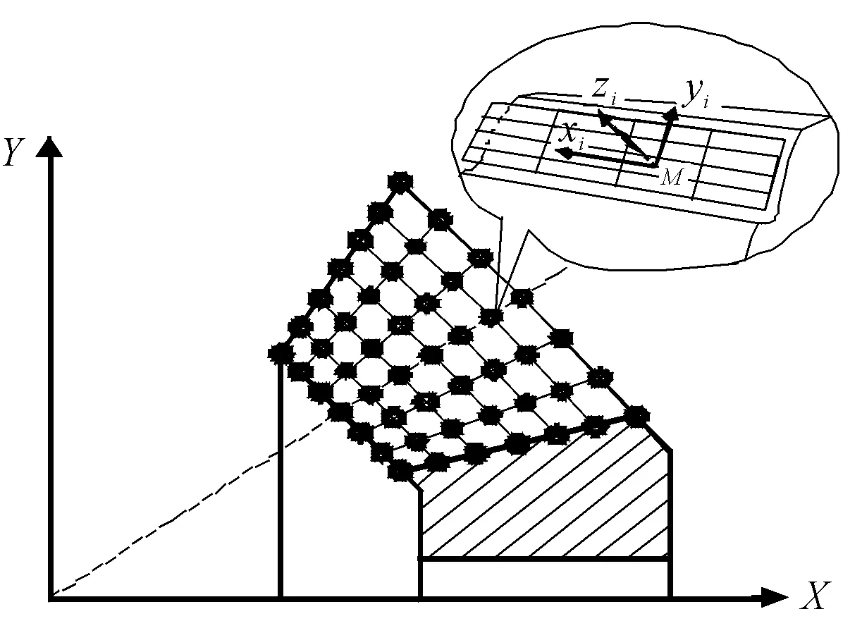
Figure 4.Obtaining data of discrete points

Figure 5. Collect the points by the measuring
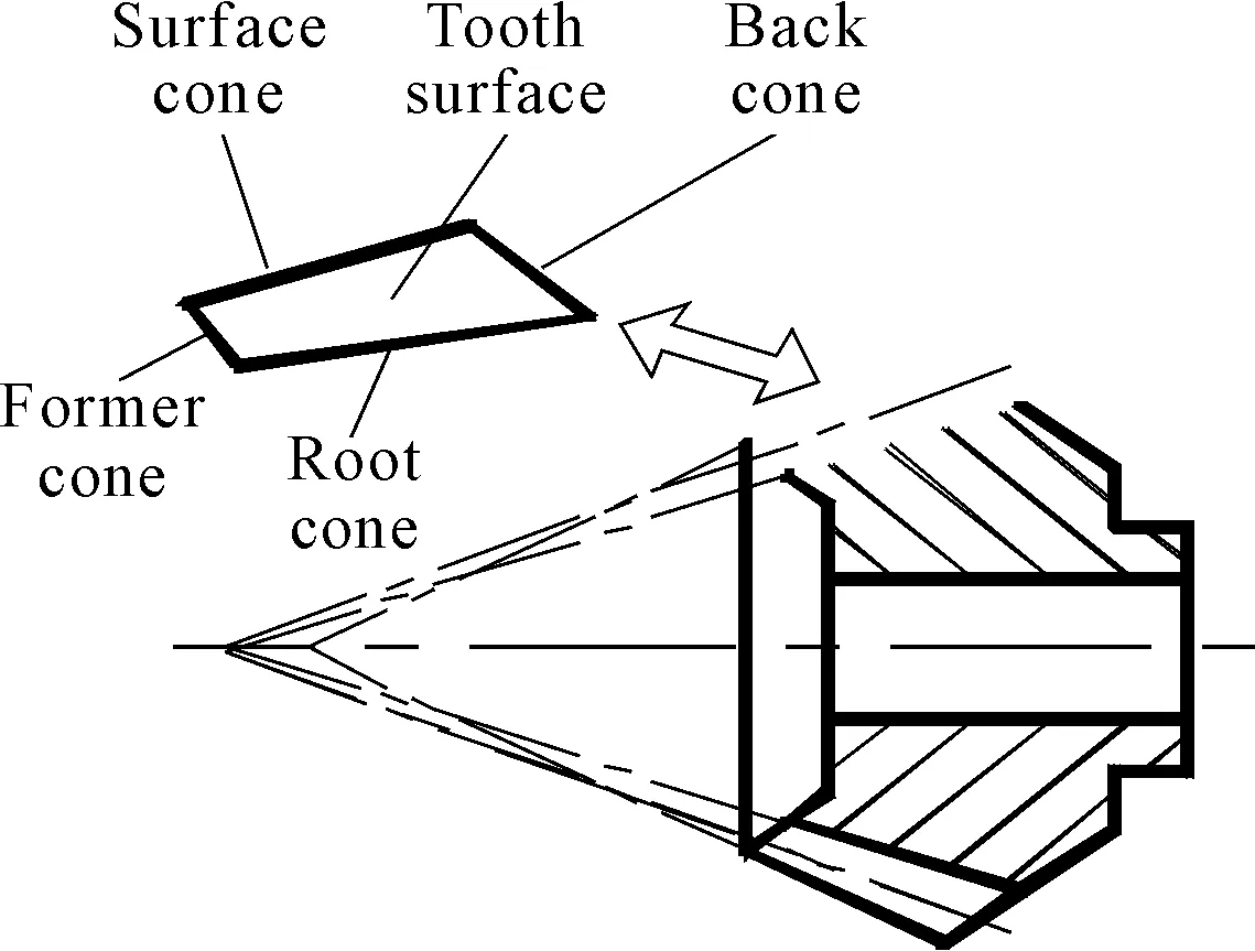
Figure 6.Intersecting surfaces
3.2.The line-to-surface modeling by suturing curves
At first, mathematical equations of the curve profile should be calculated according to the relevant theory. Then equations are imported into the 3D software, which may draw out the basic shape of the tooth surface. At last, by using of optimization method such as NURBS to improve accuracy, it can export the accurate model after the reconstruction of tooth surface. Among the procedure, the core is to solve the equation expression on the tooth curve and derivate the equations of tooth surface (Figure 7)[12-14].

Figure 7. General equation derivation of the tooth surface
Generally speaking, there are two solutions from different theoretical sources. The one base on the meshing theory that figure out the basic tooth profile curves which are exported by the software such as Matlab CAXA and so on, and the other is derivate the expression with the application of spherical involute curve. The former is complex and cumbersome. And the latter is fast and simple, easily parameterized. In the latter solution, the involute curve was used to solve the equations of tooth surface of spiral bevel and hypoid gear[5, 15, 26].
Figure 8 shows the principle that how to gain the equations of the tooth surface by using of spherical involute curve. It reveals the formation process of spherical involute tooth surface. When a circular plane π is tangent to and doing pure rolling on the base coneOK0N, the track of generated curveK0,Ktin the space is formed intoa side of the gear tooth surface. The end pointsK0andKton the generated curves form into the tooth profile curves of gear heel and toe. Changing the radiusRof circular plane π and the rotation angle of the base cone, with spherical involute basic equation, basic mathematical equation expressions of each part of the tooth curves can be derived, and finally the parametric equations are completed.
3.3.Modeling by the simulation machining based on virtual reality technology
It is a great practical significance that gets the model through virtual manufacturing technology. For the machine and the processing method some researchers[16-17] choose the traditional mechanical machine tools, they prefer (No.116) the Format and the Generated for the gear, the Tilt and the Modified Roll for the pinion. Another[18-20] choose the Phoenix®II CNC bevel cutting machine, by the equivalent conversion, the traditional methods are transformed to the NC machining method with six axes five linkages[27].

Figure 8. Formation of the spherical involute tooth surface
In actual machining[18], there are two important steps, one is the equivalent conversion between the traditional and the Phoenix®II CNC bevel cutting machine, anther is adjustment of the position and orientation of the cutter and gear blank.
1) Equivalent conversion: in order to achieve equivalent processing between the CNC machine tool and the traditional, the following two equations must be satisfied[19].
where (OpPt)pis the vector from the cutting tools to the tooth blank;Lptis transformation matrix from the cutting tools to the gear blank; CNC bevel cutting machine is represented by theC; the mechanical machine tool is represented by theG;Pandtare the coordinate systems fixed with the gear blank and the cutting tool respectively; (δ,γ,θ) and (μ,φ,ψ) are the rotation angles of the three main axes. Getting the motion parameters of the CNC cutting machine through above two simultaneous equations, the equivalent conversion can be achieved.
2) Adjustment of the position and orientation: as shown in Figure 9, the relative position must be consistent with the actual processing position all the time, the adjustment of the initial point is particularly important. The main solution is making the motion parameters from above equivalent conversion controlled by the programming. For a sentence, do secondary development in the software (CATIA, UG, Solid Works, etc) to write a real-time control program[19]. Additionally, in some simulation machining software (VERICUT,etc), it can be controlled directly by NC program[20].
The general simulation machining process with special machine tool is shown in Figure 11. After entering into simulation processing environment, the position between the cutter and gear blank must be adjusted accurately, so that they can do Boolean cutting operations[28] for a gear tooth surface. At last, the accurate model of spiral bevel and hypoid gear can be exported after reconstruction of tooth surfaces.

Figure 9. Simulation cutting machining
When it comes to the method of actual machining, some researchers adopt the general CNC machine milling[6, 29] (Figure 12). It is so different from the special machine tool processing that provides pathway for the machining, especially for big modulus gear (Gleason gear system maximum machining diameter for Φ2590 mm). Therefore, the simulation basing on the universal milling machining also gradually becomes a kind of gear modeling method. The simulation process (Figure 10) is variety due to the choice of the simulation software platform, but it includes some parts as follows:

Figure 10. Simulation milling machining
1) Setting the related configurations
Including choose the simulation software platform (such as Pro/E,UG,CATIA,etc) machine tool, the fixture, the cutter and NC simulation system. Generally speaking, to choose the five axes linkage machine tool, the choices of cutter and fixture according to the manufacturing procedure and the NC simulation system should meet the processing object.
2) Creating the workpiece blank
It is consist with the material and size, or achieved by drawing operations.
3) Setting processing parameters
Including parameters of the cutting tool, cutting feed speed, the feed, spindle rotating speed, the amount of backing should be set on the base of specific circumstances of actual processing.
4) The pre-processing
It contains compiling machining craft procedure, generating tool path, the simulation and the calculation of tool path in the CAM software.
5) The post-processing
It means transform the tool path into the movement track, and completes NC machining by generating NC code.
The vital step in simulation of milling machining is to comply with the machining craft procedure, during the simulation of spiral bevel and hypoid gear milling. Firstly, turning processing for the gear blank, secondly, the milling of tooth slots and surfaces, thirdly, grinding the gear tooth surfaces, in order to improve the quality of gear tooth surface processing, at length, making inspection, modification and adjustment to the gear contact area. The main processing technology is the milling parts that can be divided into three processes: rough machining of tooth slots, vice-finishing, and then finishing of tooth surfaces.
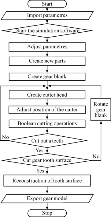
Figure 11. The process of simulation machining with special machine tool
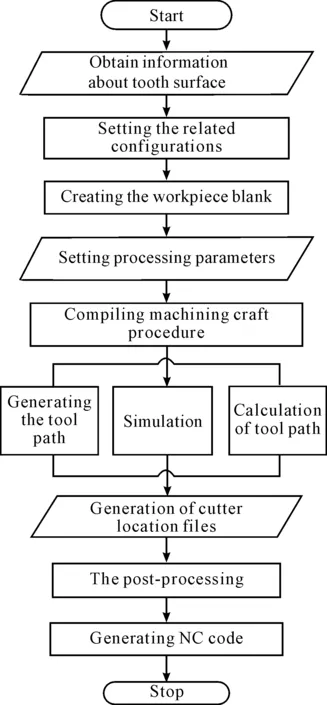
Figure 12. General machine tool
4.Outlook for the modeling of spiral bevel and hypoid gear
At present, the vital technology in digitized manufacturing are tooth contact analysis (TCA) and correction of the deviation of tooth surface, which were mastered by the Gleason Corporation and never announced[7]. The key technologies are based on the model of spiral bevel and hypoid gear. Therefore, based on the results of the present, this paper provides three directions for the modeling techniques of the spiral bevel and hypoid gear in the future.
4.1.The precision of the modeling
Taking advantage of high-speed dry, the cutting precision can reach the level of 4 or 5 in foreign country. However, there is a big gap between our nation and abroad and some problems exist in the modeling process:
① interpolation accuracy in the collecting of discrete points; ② the derivation and processing of the transitional surfaces; ③ optimization and reconstruction of the tooth surface after simulation processing; ④ measurement and correction of deviation of tooth surface.
Especially, the transitional surface is a serious problem, but often paid little attention or not mentioned due to the complex modeling. However, it is the integral part of the actual machining tooth surface. As shown in Figure 13, a complete tooth profile consists of at least four segments: the segmentabis tooth top; the segmentbcis working tooth profile; the segmentdeis tooth root; and the connection segment between working tooth profile and tooth root is transition curvecd. Transitional surface is posed by the transition curves, and enveloped with tooth top of the cutting tools or the rounded package of tooth top according to the tool shape[31-33].
Subsequently, more and more researchers pay attention to solve these problems. They gradually increase the accuracy of modeling by using of many optimized approaches, such as software data analysis[6,8], derivation of the equation of the transition curve[30-32], reconstruction of tooth surfaces with utilizing functions of curves and surfaces in the NURBS or Bezier[10,33]. For example, the deviation can be calculated in the reconstruction of tooth surfaces by the NURBS after suturing curves, and controlled within 10-8~10-14mm at the main curvature of gear tooth surface[10]. It has been reached a high accuracy, but accuracy problems of spiral bevel and hypoid gear tooth surface still need to be improved.
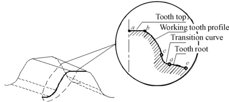
Figure 13. The basic components of the tooth profile curve
4.2.The efficiency of the Modeling
Within a variety of modeling methods researchers have proposed, there are many factors lead to the poor efficiency:
1) Theory is too hard to grasp
Merely derivation of the tooth surface equations need to familiar with a lot of meshing principle and the knowledge of the coordinate transformation and gear cutting machining[1-4].
2) Large amount of data processing
In the acquisition process of the discrete points, it has to use some optimized algorithm for solving nonlinear equations and write complex procedures to analyze the related data[10,29].
3) Cumbersome process and repeated operation
Firstly, a complicated calculation is necessary. Then 3D software trivial operation should proceed. Finally, continue to verify the actual data and do the correction and processing in order to meet the accuracy requirements[6, 34].
Needless to say, how to get a fast and accurate modeling will become an important topic. The digitized design based on machining simulation technology with the multi-axis linkages CNC machine tool will become a more important research direction[35-36]. The spherical involute-based fast parametric modeling[15,26] will also become a new hot spot. Independent development of system software[6, 35] will become the main trend of the research to replace the complicated calculations.
4.3.The flexibility of the modeling
In the past, modeling by discrete points, due to the complexity of calculation and derivation of longitudinal process, cause data stability and unrepeatable. There have been some problems about integrity and consistency of modeling platform due to the limitation of software function. Modeling problem of big modulus gear beyond the normal tooth system specifications has not been considered. Along with the further research, the modeling method and field are continuously widened. At the same time, with the development of cloud manufacturing technology, collaborative design for spiral bevel and hypoid gear based on the advantages and characteristics of the network resources will become a new bright spot. A variety of information resources in design field will be integrated to achieve seamless data sharing between computer network and user database, and complete flexible collaborative design and manufacturing[38].
The modeling technology will become digitalized, and gradually forms a flexible and multivariate system that can be controlled. Among them, development and application of multifunction data processing software[29], digitized and initiative design of tooth surface[39-40], CNC programming and multi-axis CNC system development basing on the actual needs[41], secondary development basing on simulation processing platform[42], design of spiral bevel and hypoid gear with high contact ratio[43] and other methods, will become flexible. The field of molding becomes wider, and the methods of molding become more perfect and powerful. In addition, using universal NC milling processing will promote the modeling more diversified[29, 42]. Using the theory of spherical involute to achieve faster and more accurate modeling of tooth surface make the modeling methods more colorful[5,15,26].
5.Conclusion
In this paper, the modeling methods of spiral bevel and hypoid gear are summarized from three aspects. Moreover, the existing problems in the process of modeling were analyzed and the related solutions to these problems were summed up. Three development directions were proposed for modeling technology of spiral bevel and hypoid gear in the future. Conclusions are listed as follows:
① Modeling technology by simulation process based on virtual reality has become the mainstream of the research of modeling, and will be constantly deepen and developed.
② Enough precision, efficiency, flexibility of molding will promote the manufacture technology of spiral bevel and hypoid gear high precision, high efficiency and high flexibility.
③ Comprehensive use of all kinds of related technologies in its field independent research and development of system software, making the parametric modeling technology transform to digital will be the crucial link to improve the level of digital manufacture.
④ Modeling methods and basic thoughts are summarized, and the future development directions are put forward, which will provide some approaches about fast and precise modeling of spiral bevel and hypoid gear for later researchers.
[1] Litvin F L, Wang A G, Handschuh R F.Computerized generation and simulation of meshing and contact of spiral bevel gears with improved geometry[J].Comput Methods Appl Mech Engrg,1998, 158: 35-64.
[2] Litvin F L, Fuentes A, Hayasaka K.Design, manufacture, stress analysis, and experimental tests of low-noise high endurance spiral bevel and hypoid gear[J].Mechanism and Machine Theory, 2006, 41(1):83-118.
[3] Fuentes A, Litvin F L, Mullins B R, et al.Design and stress analysis of low-noise adjusted bearing contact spiral bevel and hypoid gear[J].ASME Journal of Mechanical Design, 2002, 124:524-532.
[4] Faydor L L, Fuentes A, Qi Fan, et al.Computerized design, simulation of meshing, and contact and stress analysis of face-milled format generated spiral bevel and hypoid gear[J].Mechanism and Machine Theory, 2002, 21:775-786.
[5] Suh S H, Jih W S, Hong H D, et al.Sculptured surface machining of spiral bevel and hypoid gear with CNC milling[J].International Journal of Machine Tools &Manufacture, 2001, 41:833-850.
[6] Yanzhong Wang , Yunfei Zhou, Zuozhang Li , et al.Study on NC machining for spiral bevel and hypoid gear based on the universal CNC machine tools with five-axis[J].China Mechanical Engneering, 2001, 12(8):903-906.
[7] Fan Qi, Ron Dafoe.Gleason expert manufacturing system (GEMS) opens a new era for digitized manufacturing of spiral bevel and hypoid and hypoid gear[J].World Manufacturing Engineering & Market, 2005(4):87-93.
[8] Jingcai Li.Study on basic applied technology in the process of digitized manufacturing for spiral bevel and hypoid gear[D].Tianjin: Tianjin University, 2008, 6.
[9] Jun Wang, Xiaochun Wang, Hong Jiang, et al.Measurement of tooth surface of spiral bevel and hypoid gear[J].Chinese Journal of Mechanical Engineering, 2003, 39(6):15l-154.
[10]Zhijian Su, Xutang Wu, Shimin Mao, et al.Design of hypoid gear tooth surface represented by non-uniform rational B-spline polynomial[J].Journal of Xi’an Jiaotong University, 2007, 39(1):17-20.
[11]Yuqing Wang, Yuqing Wang, Jian Liang.Study and implementation on entity mathematical pattern of spiral bevel and hypoid gear[J].China Mechanical Engneering, 2007, 18(14):1160-1163.
[12]Faydor L L, Fuentes A, Qi Fan, et al.An invariant approach for gear generation with supplemental motions[J].Mechanism and Machine Theory, 2007(42):275-295.
[13]Suh S H, Jung D H, Lee E S, et al.Modeling, Implementation and manufacturing of spiral bevel and hypoid gear with crown[J].Advanced Manufacturing Technology, 2003(21):775-786.
[14]Ltivin F L, Seol I H, Kim D, et al.Kinematic and geometric models of gear drives.Trans[J].ASME Journal of Mechanical Design, 1996, 118(12):544-550.
[15]Zhenhai Ji, Jianzhong Duan, Jihua Gu.OpenGL-based 3D parameterization model for involute spiral bevel and hypoid gear[J].Journal of Engineering Design, 2009, 16(6):432-435.
[16]Jiaying Han, Taiyong Wang, Qing Li, et al.Computer cutting simulation and deviation analysis of tooth surface for hypoid gear[J].Manufacturing Technology & Machine Tool, 2010, (1):112-115.
[17]Chungyunn Lin, Tsay Chungbiau.Mathematical model of spiral bevel and hypoid and hypoid gear manufactured by the modified roll method[J].Mechanism and Machine Theory, 1997, 32(2):121-136.
[18]FAN Q.Computerized modeling and simulation of spiral bevel and hypoid and hypoid gear manufactured by Gleason face hobbing process[J].Journal of Mechanical Design, 2005, 128(6):1315-1327.
[19]Jinyuan Tang , Yanping Liu , Taiping Pu .Simulation for tilt manufacturing of spiral bevel and hypoid gear based on five-axes CNC machine tool[J].Journal of Beijing University of Technology, 2011, 37(4):487-493.
[20]Yanwei Xu, Lianhong Zhang, Wei Wei, et al.Virtual machining on monolithic structure spiral bevel and hypoid gear milling machine[J].Transactions of the CSAE, 2008, 24(12):71-75.
[21]Zeng T.Design and manufacture of spiral bevel and hypoid gear[M].Harbin: Harbin Institute of Technology Press, 1989:24-46.
[22]Changqi Zheng. Spiral bevel and hypoid gear[M].Machinery Industry Press,1988:60-61.
[23]Jingcai Li, Taiyong Wang, Gaiyun He, et al.3D solid accurate modeling of spiral bevel and hypoid gear based on manufacture method and meshing theory[J].Journal of Jilin University (Engineering and Technology Edition, 2008, 38(6):1315-1319.
[24]Wang P Y, Fong Z H.Adjustability improvement of face-milling spiral bevel and hypoid gear by modified radial motion (MRN) method[J].Mechanism and Machine Theory, 2005, 40:69-89.
[25]Jun Wang.Research on geometric precision control method of spiral bevel and hypoid gear and hypoid gear based on three coordinates measuring[J].Xi’an: Xi’an Jiaotong University, 2000:20-40.
[26]Ben Wang, Lin Hua.Accurate parametric modeling of spiral bevel and hypoid gear based on CAD software Pro/E[J].Journal of Wuhan University of Technology, 2010, 32(10):99-103.
[27]Goldrich R N.Theory of 6-axis CNC generation of spiral bevel and hypoid gear and hypoid gear[J].AGMA Paper, 1989 (NO.89-FTM-9):12-17.
[28]Jiangang Li, Xutang Wu, Jingliang He, et al.Research on the machining simulation system for cutting curved tooth bevel gears on CNC gear generator[J].Journal of System Simulation, 2003, 15(4):499-501.
[29]Lin Shi, Research on key CNC machining technology for spiral bevel and hypoid gear[D].Xiamen: Xiamen University, 2008.
[30]Jinyuan Tang, Kang Cao,Jin Du, et al.Accurate modeling of the tooth-surface of a spiral bevel and hypoid gear with fillet[J].Mechanical Science and Technology for Aerospace Engineering, 2009, 28(3):317-321.
[31]Guanglei Liu, Weihong Fan.Precise finite element modeling of spiral bevel and hypoid gear with fillet[J].Mechanical Science and Technology for Aerospace Engineering, 2010, 29(12):1595-1601.
[32]Wei Wei, Lianhong Zhang.Solid modeling of spiral bevel and hypoid gear considering cutter fillet and undercutting[J].Journal of Machine Design, 2011, 28(3):9-12.
[33]Yuwen Sun, Hongjun Liu, Jian Liu.Research on the method of accurate NURBS surface fitting to scattered points[J].Chinese Journal of Mechanical Engineering, 2004, 40(3):10-14.
[34]Hongbin Yang, Xiaoqian Wang.3D modeling design of spiral bevel and hypoid gear[J].Machinery Design & Manufacturer, 2009(7):34-36.
[35]Kai Liu, Dongbiao Zhao, Peijian Huang.Planning of Generating Motion Trajectory in the NC Machining of Spiral bevel and hypoid Gear[J].Journal of South China University of Technology (Natural Science Edition), 2007, 35(8):32-37.
[36]Wei Liu, Yaping Wang, Hongwei Li, et al.Research and application of VERICUT in CNC machining optimization[J].Application Research of Computers, 2004,21(7):102-104.
[37]Chung Y L, Chung B T, Zhang H F.Computer-aided manufacturing of spiral and hypoid gear by applying optimization techniques[J].Journal of Materials Processing Technology, 2001, 114:22-35.
[38]Dongfeng Ren, Zongde Fang.Research of network-based and concurrent engineering-oriented spiral bevel and hypoid gear cooperative design system[J].Computer Engineer and Application, 2003, 39(14):17-21.
[39]Binyang Wei, Xiaozhong Deng, Mingqi Wang .Digital design and integrated manufacturing of spiral bevel and hypoid gear design[J].Journal of Mechanical Transmission, 2003, 5:32-33.
[40]Xuncheng Wu, Shimin Mao, Benhe Gao, et al.A study on the function-oriented design and advanced manufacturing technology for tooth surfaces of hypoid gear[J].Automotive Engineering, 2001, 23(1):30-32.
[41]Yanzhong Wang, Lu Gao, Xingfu Zhao, et al.The singularity in the parallel machining of the spial bevel gear[J].Mechanical Tool & Hydradulics, 2007, 35(1):1-3, 32.
[42]Chunrong Chen, Bin Yao, Lin Shi.An innovative modeling method of spiral bevel and hypoid gear base on UG[J].Manufacturing Information Engineering of China, 2007, 36(23):28-32.
[43]Xiaozhong Deng, Zongde Fang, Bingyang Wei.Design and experiment of spiral bevel and hypoid gear with high contact ratio[J].Chinese Journal of Mechanical Engineering, 2004, 40(6):95-99.
弧齿锥齿轮和准双曲面齿轮模型设计的方法及展望*
米小红†, 阿达依·谢尔亚孜旦,丁 撼
新疆大学 机械工程学院,乌鲁木齐 833046
在弧齿锥齿轮和准双曲面齿轮的数字化制造中,精确模型是其关键技术—齿面接触分析技术(TCA)和齿面误差修正技术的基础。总结和归纳了近些年来国内外相关研究成果,将弧齿锥齿轮和准双曲面齿轮的模型设计方法分成离散点、曲线拟合、仿真加工模型设计3种类型,并概括了其关键思想与步骤。同时,分析了模型设计过程中存在的一些问题与不足,整合先进方法和思想,对未来弧齿锥齿轮和准双曲面齿轮模型设计研究提出了高精度、高效率、高柔性3个发展方向,为弧齿锥齿轮和准双曲面齿轮更加快捷精确地设计和加工提供了参考。
精确建模;弧齿锥齿轮准双曲面齿轮; 数字化制造;齿面接触分析技术(TCA); 仿真加工
TH128
2013-08-12
10.3969/j.issn.1001-3881.2014.12.012
*Project supported of National Natural Science Foundation of China (No.50965017)
† Xiao-hong MI, E-mail: mixiaohong0205@163.com
猜你喜欢
制造技术与机床(2022年5期)2023-01-06
机械设计与制造(2021年2期)2021-03-05
制造技术与机床(2019年11期)2019-12-04
制造技术与机床(2019年8期)2019-09-03
振动与冲击(2019年3期)2019-02-21
山东冶金(2018年5期)2018-11-22
江西建材(2018年2期)2018-04-14
制造技术与机床(2017年3期)2017-06-23
光学精密工程(2016年6期)2016-11-07
西南交通大学学报(2016年6期)2016-05-04

- 机床与液压的其它文章
- A Simple time-domain method for bearing performance degradation assessment*
- Structural design and performance testing of the electromagnetic proportional pressure relief valve
- Analysis of magnetic field characteristics for different winding cylinder materials of a new type of magnetorheo-logical damper*
- Impacts of centrifuge errors on calibration accuracy of error model coefficients of gyro accelerometer*
- Interior ballistic simulation and parameter influence analysis of an underwater pneumatic launcher*
- Influence of airflow uniformity over the duct outlet of vehicle air-condition on cooling performance*