稀疏网格求积分滤波算法在SINS/GPS紧组合导航中的应用
2014-10-21 01:07KeyLaboratoryofMicroInertialInstrumentandAdvancedNavigationTechnologyMinistryofEducationSoutheastUniversityNanjing210096ChinaSpaceStarTechnologyCoLtdBeijing100086China
中国惯性技术学报 2014年6期
(1. Key Laboratory of Micro Inertial Instrument and Advanced Navigation Technology, Ministry of Education, Southeast University, Nanjing 210096, China; 2. Space Star Technology Co. , Ltd. , Beijing 100086, China)
(1. Key Laboratory of Micro Inertial Instrument and Advanced Navigation Technology, Ministry of Education, Southeast University, Nanjing 210096, China; 2. Space Star Technology Co. , Ltd. , Beijing 100086, China)
High-precision navigation information is crucial for high altitude vehicles. Considering the characteristics of high-altitude aircrafts, we select the launch inertial coordinate system as the navigation coordinate system and propose a mathematic model for tightly-coupled SINS/GPS integrated navigation system based on pseudo-range and pseudo-range rate. As the state equations and measurement equations are nonlinear, the sparse grid quadrature filter (SGQF) is adopted. The method proposed in this paper is fit for both aligning and navigating, so it is more efficient compared with the method that designs aligning and navigating separately. Simulation results indicate that, owing to this strong nonlinear system, the sparse grid quadrature filter can not only estimate navigation parameters faster but also more accurately than the unscented Kalman filter (UKF) during the take-off phase of high-altitude aircrafts. They also show that the sparse grid quadrature filter with tightly-coupled integration can greatly improve estimation accuracy of navigation compared with that with loose integration algorithm. Finally, the impact of different levels of accuracy of inertial devices is studied. The result indicates that tightly-coupled integration with SGQF can perform quite well within a large range of accuracy of inertial devices.
SINS/GPS; tightly-coupled integration; alignment; navigation; sparse grid quadrature; nonlinear filter
Strap-down inertial navigation systems (SINS)/ global positioning system (GPS) integrated navigation system can provide high accuracy and reliability with low cost, and it has become a hot issue for researches in integrated navigation. Today, most of the integrated navigation systems are loose integration system, but they can’t work well with less than four satellites and have lower precision than tightly-coupled integration system[1]. Considering the characteristics of high altitude vehicles, we select the launch inertial coordinate system as navigation coordinate system and propose a mathematic model for the tightly-coupled SINS/GPS integrated navigation system based on pseudo-range and pseudo-range rate.
The state equations and measurement equations of the tightly-coupled SINS/GPS integration system are nonlinear when misalignment angles are large. Much has been done to deal with the nonlinearity. With the assumption of small misalignment angles, Zhang linearizes the measurement equations and estimates the integrated navigation system with Kalman filter[2]. A better way of linearizing is to introduce a second-order derivate term into linearity equations[3]. To avoid errors of linearization and obtain higher accuracy, UKFs are applied in tightly-coupled INS/GPS navigation system[4-5].
The sparse grid method[6-7], proposed by Smolyak in 1963, is a multi-dimensional integral method. When applied to nonlinear filter field, it becomes sparse grid quadrature filter algorithm. By selecting appropriate points, this method does not need to linearize nonlinear equations, so it can overcome errors due to linearization. Compared with UKF, it is more flexible and more accurate and can obtain much better performance by adding the number of quadrature points[8]. This paper will apply this algorithm to tightly-coupled SINS/GPS integrated navigation system and compare its performance with other existing algorithms. A mathematic model for this system is also proposed here.
1 Mathematic model for navigation system
1.1 State equation
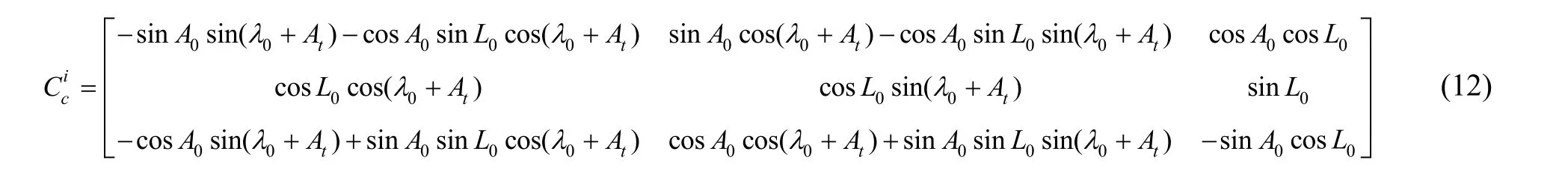
Set launch inertial coordinate system as navigationcoordinate system. The launch inertial coordinate system coincides with launch gravity coordinate system at launching time. In the launch inertial coordinate system, the origin of coordinate is at launch point o, oy axis is along the opposite direction of gravity, ox axis is vertical to oy axis and points to the launch direction, and oz axis is defined using the right-hand rule. The following error state equation is applied in this paper.

where X(t) is a 17×1 system state vector; W is the process noise sequence. X(t) is defined as follows:
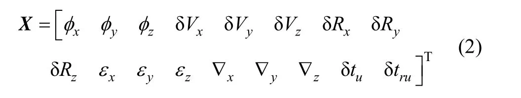
where φx, φy, φzare the misalignment angles; δVx, δVy, δVzare the velocity errors; δRx, δRy, δRzare the position errors; εx, εy, εzare constant gyro drift; ▽x, ▽y, ▽zare constant accelerometer offsets; δtuis the distant corresponding to equivalent clock error; δtruis the distant rate corresponding to the equivalent clock frequency error. The differential equations are established as follows:
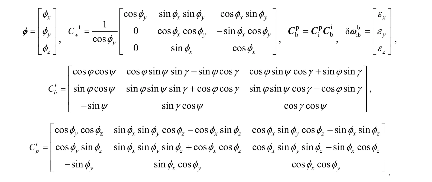
① Misalignment errors equation:

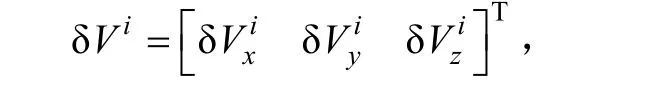
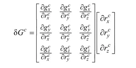
② Velocity error equation:

Gravity acceleration in earth center inertial coordinate frame can be described as follows:
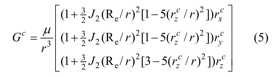
where J2is the coefficient of second-order zonal harmonics. Reis the radius of the earth. r is the position vector of vehicle in earth center inertial coordinate system. If we put disturbance to Eq. (4), we get
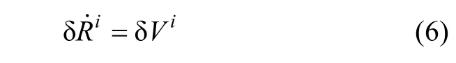
③ Position error equation:
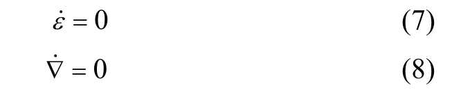
④ The error equations of gyro and accelerometer are:
⑤ The error equations of distant corresponding to equivalent clock error and distant rate corresponding to the equivalent clock frequency error are:

1.2 Measurement equation
The following measurement equation is applied in this paper.
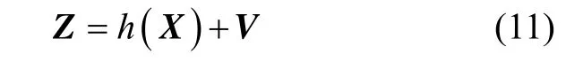
where Z is a 8×1 observation vector;V is the observation zero-mean white noise vector. Z is defined as follows:

where the nonlinear measurement equation of pseudo range is
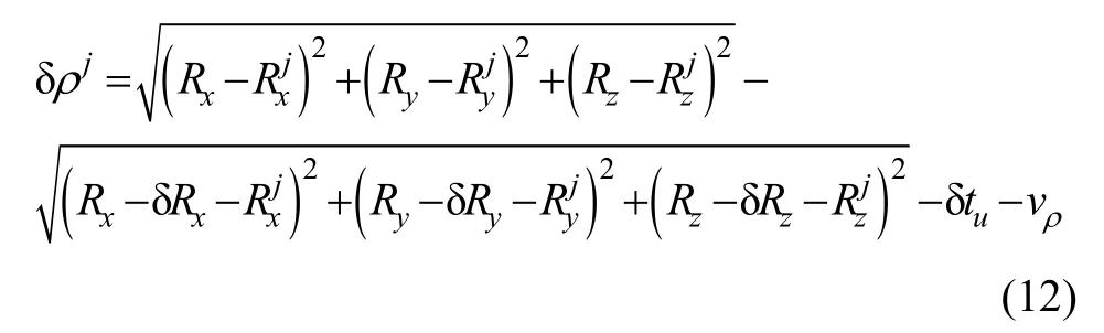
where Rx, Ryand Rzare vehicle’s positions.,andare the j-th satellite’s positions.
The measurement equation of pseudo range rate can be described as:
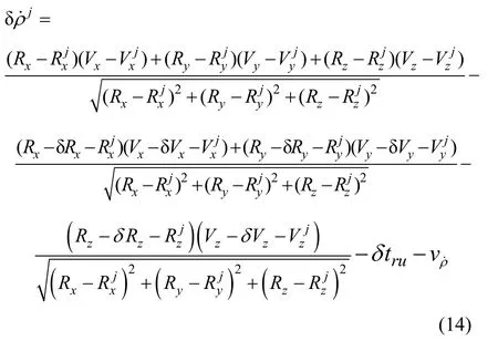
where Vx, Vyand Vzare vehicle’s velocity.,andare the j-th satellite’s velocity.
2 Sparse grid quadrature filter
2.1 Nonlinear Gaussian filter
Nonlinear Gauss approximate filter in the Bayesian framework is a suboptimal filtering algorithm on the assumption of Gauss noise, and includes prediction step and updating step.
① Prediction Step:
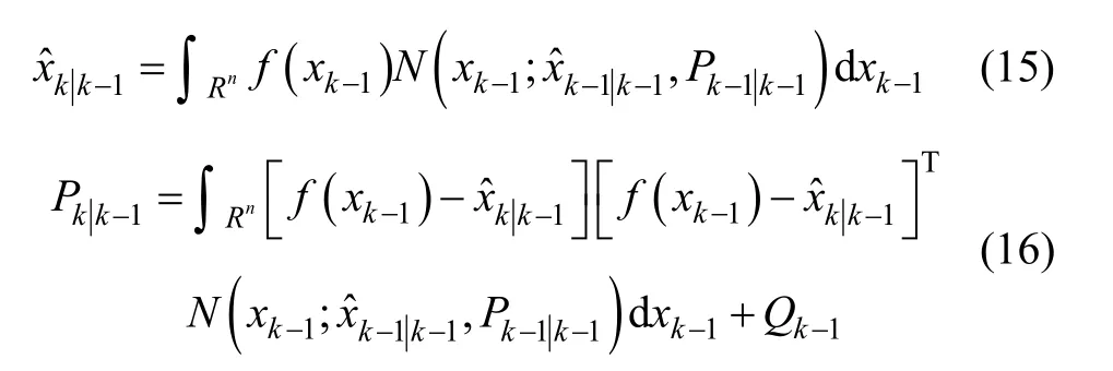
② Update Step:
Suppose that the predictive density function p(xk|zk-1)

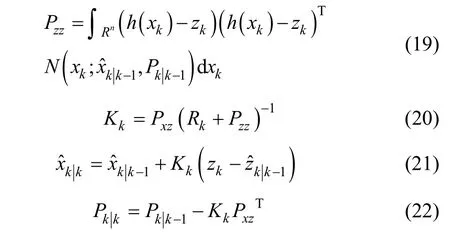
It is difficult to get analytic solutions for Gauss cubature, but we can get approximate solutions using numerical quadrature methods. Gauss quadrature can be approximated by
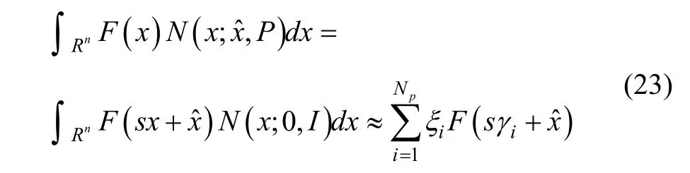
where the quadrature points γiand the weights ξican be chosen according to different rules, such as Gauss-Hermite quadrature rule, unscented transformation and so on. Npis the number of the quadrature points, and P=ssT.
2.2 Sparse grid quadrature filter
Sparse grid method utilizes a linear combination of low-level tensor products of univariate quadrature rules to approximate multivariate integrals. The method can break the curse of dimensionality to some extent, so it can reduce the computational work. Sparse grid quadrature filter can be given as[9]:
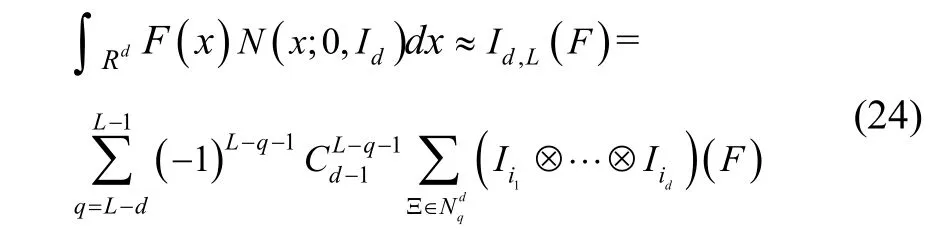
where Id,L(F) is an approximation to the d-dimensional integral of the function F with respect to Gauss distribution function with the accuracy level of L. ⊗denotes tensor product. Iikis the univariate quadrature rule with the accuracy level of ik∈Ξ, where Ξ is an accuracy level sequence of d natural numbers. Nqdis the set of accuracy level sequences defined by
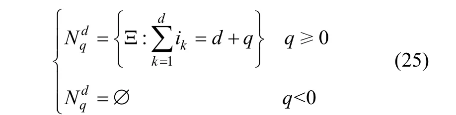
The more explicit form of Eq. (24) given by Heiss and Winschel[10]can be written as
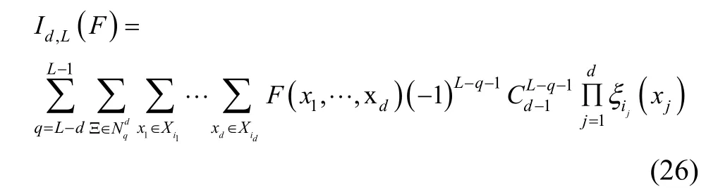
where quadrature points (x1, …, xd) are a combination of all points determined by univariate quadrature rule. The accuracy level i in each dimension is determined by∈and L-d≤q≤L-1, and the corresponding weight isThe set of sparse grid quadrature points is given by

The meaning of Eq. (27) is that, for a certain q, we can get d-dimension quadrature points by combining univariate quadrature points, and that we can then traverse all d-dimension quadrature points according to q. Bungartz[7]proved that the number of quadrature points would grow polynomially instead of exponentially. Therefore it could break the curse of dimensionality and reduce computational work to some extent.
2.3 Gauss-Hermite quadrature rule
As we know from Eq. (27) the d-dimensional quadrature points are a combination of univariate quadrature points and the univariate integral function obeys Gauss distribution. Thus the Gauss-Hermite quadrature rule is adopted, which can be written as:
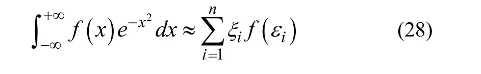
where f(x) is integrand. n is the number of quadrature points; εiand ξiare quadrature points and weights, respectively. According to the relationship between Gauss integral and orthogonal polynomial, we can compute the univariate quadrature points and corresponding weights by decomposing a symmetric tri-diagonal matrix[11]. The quadrature points and corresponding weights of accuracy levels 1, 2 and 3 are listed in Tab. 1.
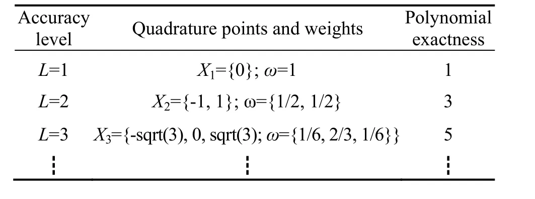
Tab.1 Gauss-Hermite quadrature points
3 Simulation results and analysis
The high altitude vehicle is assumed to be located at a longitude of 116.346° east, a latitude of 39.984° north and height of 0 m. The vehicle launches vertically for 10 s, followed by pushover to achieve nearly level flight. The initial head angle error, pitch angle error and roll angle error are 60°, 7° and 7°, respectively. The gyro constant drifts along three axes of body frame are 0.03 (°)/h with white noise 0.001 (°)/√h. The accelerometer biases along three axes of body frame are 0.1mg with white noise 0.05 mg. The pseudo-range measurement error of the receiver is 15 m, and the pseudo-range rate measurement error of the receiver is 0.2 m/s with the corresponding time of 3600 s. The measurement data are obtained from IMU at a rate of 100 Hz and from GPS at a rate of 1 Hz. The filtering period is 1 second and the simulation time is 20 minutes.
A comparison of alignment accuracy and time between SGQF and UKF is given in Tab. 2. To show the advantage of SGQF explicitly, the curves of errors are given in Fig. 1 to Fig. 3. Tab. 3 indicates the performance of estimation accuracy between tightly-coupled integration and loose integration with SGQF. And to show it explicitly, Fig. 4 and Fig. 5 are drawn.
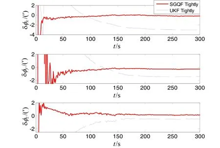
Fig.1 Curves of misalignment errors of tightly-coupled integration with SGQF and UKF
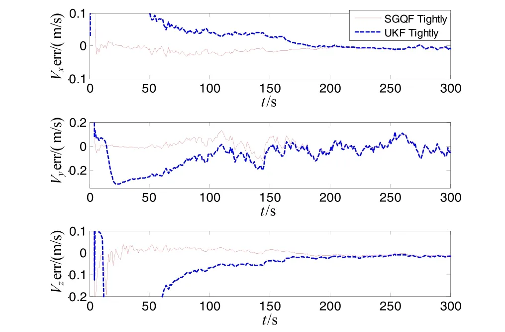
Fig.2 Curves of velocity errors of tightly-coupled integration with SGQF and UKF
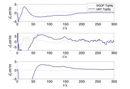
Fig.3 Curves of position errors of tightly-coupled integration with SGQF and UKF
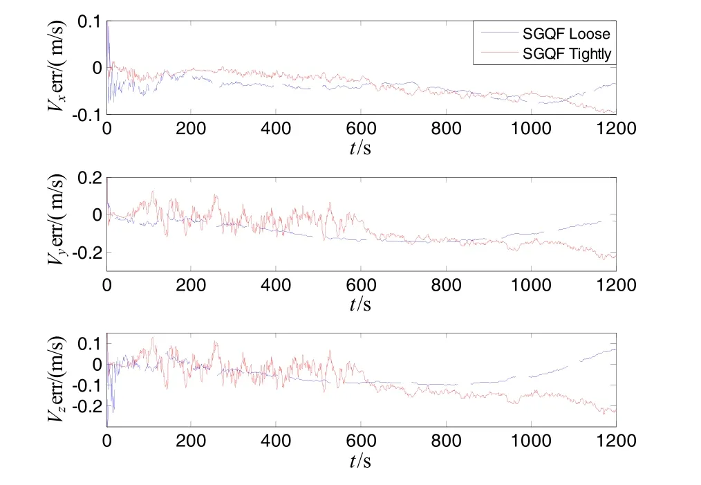
Fig.4 Curves of velocity errors of tightly-coupled integration and loose integration with SGQF
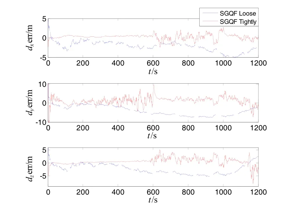
Fig.5 Curves of position errors of tightly-coupled integration and loose integration with SGQF
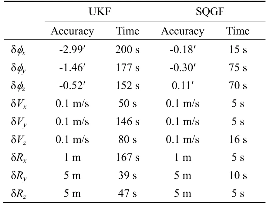
Tab.2 Alignment accuracy and time oftightly-coupled integration with SQQF and UKF

Tab.3 Estimation errors of tightly-coupled integration and loose integration with SGQF
To compare the performance of tightly-coupled integration with SGQF with different accuracy of inertial devices, we set six cases as shown in Tab. 4. The simulation results in different cases above are given in Tab.4.
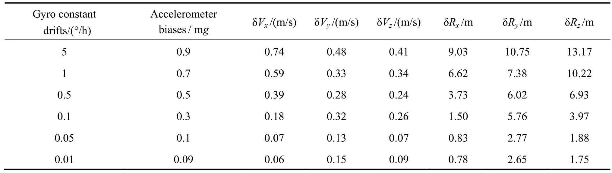
Tab. 4 Tightly-coupled integration with SGGQF under different accuracy of inertial devices
4 Conclusion
① The estimation errors of misalignment angles with SGQF is less than 0.30′, and alignment time of misalignment angles is less than 75 s. The alignment time of velocity and position is less than 16 s. During the take-off phase of high-altitude aircrafts, sparse grid quadrature filter can estimate navigation parameters faster and more accurately than UKF owing to this strong nonlinear system.
② The velocity errors of tightly-coupled integration with SGQF is less than 0.2 m/s, and the position errors of tightly-coupled integration with SGQF is no more than 3 m. Sparse grid quadrature filter with tightly-coupled integration can greatly improve the estimation accuracy of navigation compared with that using loose integration algorithm.
③ The sparse grid quadrature filter with tightly-coupled integration can perform well within a large range of accuracy of inertial devices, which means it can work well with low precision MEMS or high precision fiber optic gyroscope and so on.
[1] Zheng Xin, Fu Mengyin. SINS/GPS tightly-coupled integrated navigation [J]. Journal of Chinese Inertial Technology, 2011, 19(1): 33-37.
郑辛,付梦印. SINS/GPS紧耦合组合导航[J]. 中国惯性技术学报,2011,19(1):33-37.
[2] Zhang Jinliang, Zhang Tao, Jiang Xuehuan, Wang Sishan, et al. Tightly coupled GPS/INS integrated navigation algorithm based on Kalman filter[C]//2012 Second International Conference on Business Computing and Global Information, 2012: 588-591.
[3] Wang Wei, Liu Zongyu, Xie Rongrong. An improved tightly coupled approach for GPS/INS integration[C]// Proceeding of the 2004 IEEE Conference on Robotics, Automation and Mechatronics, 2004: 1164-1167.
[4] Bao Qilian, Zhou Yuanyuan. Design of GPS/SINS pseudorange (pseudo-range rate) integrated navigation system based on UKF[J]. Journal of Chinese Inertial Technology, 2008, 16(1): 78-81.
鲍其莲,周媛媛. 基于UKF的GPS/SINS伪距(伪距率)组合导航系统设计[J]. 中国惯性技术学报,2008,16(1):78-81.
[5] Akça T, Demirekler M. An Adaptive Unscented Kalman Filter for Tightly Coupled INS/GPS Integration[C]// Position Location and Navigation Symposium (PLANS), IEEE/ION. 2012: 389-395.
[6] Bungartz H J, Dirnstorfer S. Higher order quadrature on sparse grids[C]//Computational Science-ICCS, 2004: 394-401.
[7] Gerstner T, Griebel M. Numerical integration using sparse grids[J]. Numerical Algorithms, 1988, 18(3-4): 209-232.
[8] Wang Haipeng. Research and application of quadrature Kalman filter based on sparse-grid theory[D]. Southeast University, 2013.
王海鹏. 基于稀疏网格理论的积分卡尔曼滤波算法研究及应用[D].东南大学, 2013.
[9] Wasilkowski G W, Wozniakowski H. Explicit Cost Bounds of Algorithms for Multivariate Tensor Product Problems[J]. Journal of Complexity, 1995, 11(1): 1-56.
[10] Heiss F, Winschel V. Likelihood Approximation by Numerical Integration on Sparse Grids[J]. Journal of Econometrics, 2008, 144(1): 62-80.
[11] Bin Jia, Ming Xin, Yang Cheng. Sparse-grid Quadrature Nonlinear Filtering[J]. Automatica, 2012, 48(2): 327-341.
1005-6734(2014)06-0799-06
10.13695/j.cnki.12-1222/o3.2014.06.018
稀疏网格求积分滤波算法在SINS/GPS紧组合导航中的应用
程向红1,王晓飞1,刘峰丽2
(1. 东南大学 微惯性仪表与先进导航技术教育部重点实验室,南京 210096;2. 航天恒星科技有限公司,北京 100086)
高精度的导航信息对于高空飞行器至关重要。针对高空飞行器的特点,选取发射点惯性坐标系为导航坐标系,建立基于伪距、伪距率的SINS/GPS紧组合导航系统数学模型。针对该系统的状态方程和量测方程非线性的特性,采用基于稀疏网格求积分滤波算法。整个设计实现了对准与导航的一体化,避免了将对准与导航分别设计的繁琐过程。仿真结果表明,在飞行器起飞阶段,由于系统的非线性较强,稀疏网格求积分滤波算法比 UKF滤波算法的对准精度更高,并且对准速度更快;通过比较稀疏网格求积分滤波算法在不同组合方式下的估计效果,可以看出采用紧组合方式可以明显提高导航精度。最后采用不同精度的传感器进行仿真,结果表明基于稀疏网格求积分滤波算法的紧组合算法能够适用的传感器精度范围较广。
SINS/GPS;紧组合;对准;导航;稀疏网格;非线性滤波
U666.1
A
2014-07-28;
2014-10-13
中国航天科技集团公司卫星应用研究院创新基金资助(2014_CXJJ_DH_08);总装预研项目(513090604)
程向红(1963—),女,教授,博士生导师,从事惯性技术及其应用研究。E-mail:xhcheng@seu.edu.cn
Application of sparse grid quadrature filter to tightly-coupled SINS/GPS integrated navigation system
CHENG Xiang-hong1, WANG Xiao-fei1, LIU Feng-li2
猜你喜欢
地理空间信息(2022年10期)2022-10-31
现代测绘(2022年3期)2022-07-23
中学生数理化·八年级物理人教版(2022年3期)2022-03-16
中学生数理化·八年级物理人教版(2021年3期)2021-07-22
矿山测量(2020年6期)2021-01-07
当代陕西(2018年12期)2018-08-04
中国惯性技术学报(2017年1期)2017-06-09
探测与控制学报(2015年4期)2015-12-15
导航定位学报(2015年2期)2015-06-05
中学生数理化·八年级物理人教版(2014年1期)2015-01-09