
Synthesis and Application of a Zeolite-containing Composite Material Made from Spent FCC Catalyst
2015-06-22 14:19ZhengShuqinHeLijunYaoHuaRenShaoYuHongxiaZhangJiance
中国炼油与石油化工 2015年4期
Zheng Shuqin; He Lijun; Yao Hua; Ren Shao; Yu Hongxia; Zhang Jiance
(1. Department of Chemistry and Chemical Engineering, Hunan Institute of Science and Technology, Yueyang 414006; 2. Hunan province Key Laboratory of Specialty Petrochemicals Catalysis and Separation, Yueyang 414000; 3. Hunan Juli Catalyst Co., Ltd., Changsha 410000)
Synthesis and Application of a Zeolite-containing Composite Material Made from Spent FCC Catalyst
Zheng Shuqin1,2; He Lijun1; Yao Hua3; Ren Shao1; Yu Hongxia1; Zhang Jiance1,2
(1. Department of Chemistry and Chemical Engineering, Hunan Institute of Science and Technology, Yueyang 414006; 2. Hunan province Key Laboratory of Specialty Petrochemicals Catalysis and Separation, Yueyang 414000; 3. Hunan Juli Catalyst Co., Ltd., Changsha 410000)
Novel composite material with a wide pore distribution was synthesized by an in situ technique using spent FCC catalyst as raw material. The characterization results indicated that the composite material contained 56.7% of zeolite Y and exhibited a much larger specific surface area and pore volume as well as strong hydrothermal stability. Fluid catalytic cracking (FCC) catalyst was prepared based on the composite material. The results indicated that the as-prepared catalyst possessed a unique pore structure that was advantageous to the diffusion-controlled reactions. In addition, the attrition resistance, activity and hydrothermal stability of the studied catalyst were superior to those of the reference catalyst. The catalyst also exhibited excellent nickel and vanadium passivation performance, strong bottoms upgrading selectivity, and better gasoline and coke selectivity. In comparison to the reference catalyst, the yields of the gasoline and light oil increased by 1.61 and 1.31 percentage points, respectively, and the coke yield decreased by 0.22 percentage points, and the olefin content in the produced gasoline reduced by 2.51 percentage points, with the research octane number increased by 0.7 unit.
FCC spent catalyst; composite material; porous structure; resid catalyst; catalytic properties
1 Introduction
Spent catalysts form a major source of solid wastes in the petroleum refining industry[1-2]. The quantity of spent catalysts will increase further in the coming years because of a steady increase in the processing of heavier feedstocks with high contents of sulfur, nitrogen, asphaltenes and heavy metals together with a rapid growth in diesel hydrotreating capacity to meet the increasing demand for clean fuels with ultra-low sulfur levels. The spent FCC catalyst derived from the cracking of petroleum in the oil refining industry is a waste material consisting principally of active silica, alumina, zeolite and metals such as Fe, Ni, Cu and V in appreciable concentrations[3-4].
In recent years, increasing emphasis has been placed on the development of processes for recycling the spent catalyst materials as much as possible. Utilization of spent catalysts as raw materials in the production of other valuable products is an attractive option for recycling spent catalysts from the environmental and economical points of view. Spent FCC catalysts have been successfully used for producing cement and synthesizing NaX and 4A zeolite[5-9].
This paper will seek for recovery of the FCC spent catalyst by a new synthesis process involving spray dying, calcination, hydrothermal crystallization and modification. The XRD and N2adsorption-desorption analyses for the spent catalyst have been also performed for the purpose of exploring the surface properties. Then, the main interest in the spent catalyst is related to their high activity toward crystallization. The Y zeolite containing composite material and the resid FCC catalyst synthesized from spent FCC catalyst have been investigated.
2 Experimental
2.1 Materials
The spent FCC catalyst was obtained from the Yueyang Zhonghe Chemical Company (China), and kaolin was obtained from the China Kaolin Co., Ltd.
Sodium silicate (containing 22.8% of SiO2and 6.9% ofNa2O) and sodium meta-aluminate (containing 20.8% of Na2O and 3.0% of Al2O3) were purchased from the Yueyang Jucheng Chemical Co., Ltd.
2.2 Modification of spent FCC catalyst
The spent FCC catalyst and ammonium sulfate were blended at a mass ratio of 1:1, and then calcined at 550 ℃for 2 h (calcined spent FCC catalyst).
Deionized water, calcined spent FCC catalyst and a certain amount of hydrochloric acid solution (containing 5% of HCl) were added to a beaker, then the above ingredients were stirred at a speed sufficient to suspend the solids under the modified conditions covering a room temperature of 0.5 h, a liquid to solid mass ratio of 3, and a pH value of 3.5—4.5.
The reactant slurry was separated from their mother liquor by vacuum filtration on the Buchner funnels, washed with warm deionized water, and dried at 120 ℃ in an oven. The properties of the modified spent FCC catalyst, the spent FCC catalyst and kaolin are listed in Table 1.

Table 1 The properties of raw materi
2.3 Synthesis of composite material
The typical synthesis of composite material involved the following steps:
Sodium silicate, sodium carbonate and kaolin were mixed together to form the precursor microspheres by spray drying. The microspheres were calcined at 970 ℃ for 2 h to produce the calcined microspheres.
Sodium silicate, sodium hydroxide, distilled water, zeolite initiator, modified spent FCC catalyst and calcined microspheres were mixed in a reactor and heated to 95—97 ℃for 28 h to synthesize composite material containing Y zeolite as microspheres. The synthesis of composite material involved an inorganic reaction with a stoichiometric ratio of Na2O:SiO2:Al2O3:H2O = 6.1:12:1:300.
After crystallization, the solid product was filtered and washed with distilled water followed by drying to prepare the composite material.
2.4 Catalyst preparation
The catalyst was prepared from the as-synthesized composite material. Firstly, the composite material was exchanged one or more times with the ammonium chloride solution. Then, the microspheres were exchanged with the lanthanum chloride solution, followed by calcination at 500~600 ℃ in the presence of 100 % steam for 2 h.
2.5 Analysis and characterization
X-ray diffraction: The relative crystallinity, silica/alumina ratio, crystalline unit cell size and phase of samples were recorded on a Rigaku Ultimi IV diffractometer using Cuka radiation (λ=1.54056 Ǻ) operating at a tube voltage of 40 kV and a tube current of 30 mA. The samples were scanned at a speed of 0.2°/min. The crystallinity of reference Y zeolite was equal to 93.1%.
FT-IR test: The samples were recorded on an AVATAR 370 FT-IR spectrometer in the range of 1 400—1 600 cm-1. The acidic properties of samples were determined using the pyridine adsorption method.
SEM: The morphology and size of the samples were determined by the scanning electron microscopy (SEM) (JEOL JSM-6360) after being coated with an Au evaporated film.
N2adsorption-desorption methods: The specific surface areas, pore volumes, and pore size distribution were mea-sured on a Micrometrics ASAP 2020 sorptometer using the adsorption and desorption isotherm plots at 77 K.
Particle size distribution: A Malvern Micro-P particle size distribution analyzer was used for determining the size distribution in the samples.
2.6 Microactivity tests (MAT)
The activity of the catalyst was investigated using a microactivity test unit. The MAT conditions involved a reactor temperature of 460 ℃, a reaction time of 70 s, a weight hourly space velocity (WHSV) of 15 h–1, and a catalystto-oil mass ratio of 3.2. Prior to the MAT test, the fresh catalyst was steam-deactivated at 800 ℃ for 4 h or 17 h with 100 % steam. The feedstock oil is Dagang light diesel fuel (with its distillation range covering 235—337 ℃).
2.7 Metal contamination
The catalyst was contaminated using the Mitchell method[10]. A certain amount of ammonium vanadate and nickel nitrate was dissolved in the distilled water, and the obtained solution was mixed with the catalyst using the incipient wetness impregnation technique. The mixture was dried in an oven at 120 ℃ for 8 h and then calcined at 540 ℃ for 2 h.
2.8 Cracking performance evaluation
A comparable commercial resid catalyst was selected as the base reference FCC catalyst (RCAT). The performance of the catalyst and RCAT was tested in a smallscale fixed fluidized bed reactor (FFB). The test conditions comprised a reactor temperature of 520 ℃, a WHSV of 19 h–1, and a catalyst-to-oil mass ratio of 6. In each run, 30 g of feedstock oil was used, and the feed injection time was 33 s. Prior to the FFB test, the catalyst was steamdeactivated at 800 ℃ for 17 h with 100 % steam. The feedstock oil consisted of a mixture of 70 % of vacuum gas oil (VGO) and 30 % of vacuum tower bottom (VTB), with its properties detailed in Table 2.
3 Results and Discussion
3.1 Properties of modified spent FCC catalyst
3.1.1 X-ray diffraction
The XRD patterns of the spent FCC catalyst and the modified spent FCC catalyst are shown in Figure 1. The spent FCC catalyst and the modified spent FCC catalyst exhibited the crystalline features of Y and ZSM-5 zeolites. In comparison with the XRD patterns of the spent FCC catalyst, the modified spent FCC catalyst exhibited lowintensity peaks. By using the modified spent FCC catalyst as the raw material, the Y and ZSM-5 zeolites can serve as the solid seeds in reaction system to accelerate the crystallization rate. Figure 1 (c) exhibits that the calcined microspheres were transformed from kaolin through heat treatment under the specified treatment temperature, which resulted in an amorphous phase as the major product.
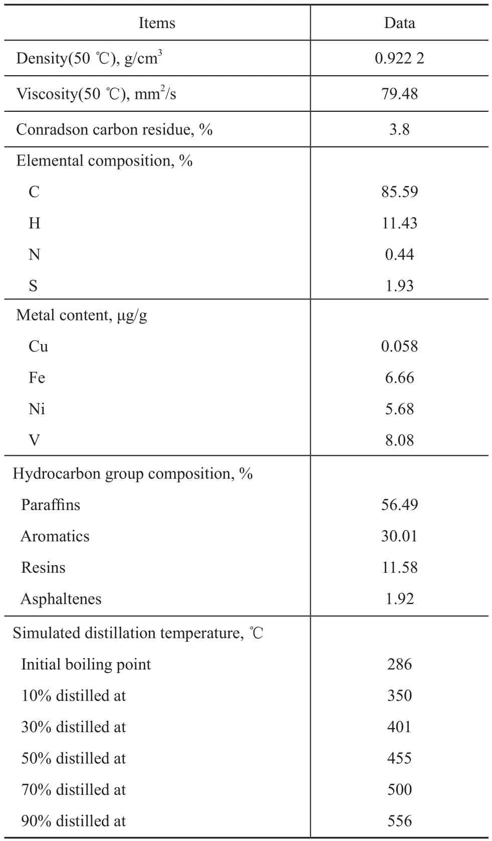
Table 2 Properties of the feedstock oi

Figure 1 XRD patterns of samples: (a) Modified spent FCC catalyst, (b) Spent FCC catalyst, and (c) Calcined microspheres
3.1.2 Pore structure characterization
Based on the results listed in Table 1, in comparison with the spent FCC catalyst, the specific surface area and pore volume of the modified spent FCC catalyst increased by 30.0 and 12.5 percentage points, respectively.
As shown in Figure 2 (upper), the isotherm for the modified spent FCC catalyst and the spent FCC catalyst exhibited the representative type IV adsorption–desorption characteristics. The hysteresis loop that occurred in a P/P0pressure range of between 0.45—1.0 was ascribed to the presence of mesopores and macropores. These results demonstrated that the modified spent FCC catalyst and the spent FCC catalyst possessed a wide pore distribution.
As shown in Figure 2 (uder), the modified spent FCC catalyst and the spent FCC catalyst were similar. The pore distribution appeared from approximately 4.0 nm to 50 nm. These results demonstrated the existence of macropores.
3.2 Properties of composite material and catalyst
3.2.1 Physicochemical properties of composite material and catalyst
During the in situ growth of the Y zeolite crystals, the modified spent FCC catalyst and the calcined microspheres reacted with the alkaline solution to form active Si-O and Al-O species, which were dissolved in the alkaline solution and became reactants in the crystallization synthesis.[11]In the current study, the unique combination of the modified spent FCC catalyst and the calcined microspheres took place during the preparation of crystallized composite material containing zeolite Y. The properties of composite material are listed in Table 3.

Figure 2 N2adsorption-desorption isotherms (upper) and pore size distribution (under) of samples:(a) modified spent FCC catalyst, and (b) spent FCC catalyst

Table 3 Properties of composite material and catalyst
It can be seen from the data listed in Table 3 that the sodium form of Y zeolite-containing microspheres of thecomposite material had a relative crystallinity of 56.7 percent by weight, and a silica/alumina molar ratio of 5.1. The composite material exhibited higher specific surface area and larger pore volume along with better attrition resistance. The unique combination of calcined microspheres and in situ technology provided an improved approach for the synthesis as compared to the traditional method.
Based on the results depicted in Table 3, the composite material containing the zeolite Y with a wide pore distribution exhibited both mesoporosity and microporosity. The composite material exhibited a higher mesopore surface area, larger mesopore volume and greater average pore diameter. The composite material possessed a large average pore diameter thanks to the specific pore structure of the modified spent FCC catalyst and kaolin. In comparison with the composite material, the NaY zeolite can be characterized as possessing a very low mesoporosity, because it consists of aggregates of single micro-crystals, which are about the size of 1 mm.
Based on the results shown in Table 3, the superior properties of catalyst were observed. The catalyst possessed a larger surface area, pore volume and average pore diameter. The wide pore distribution provided more accessible active sites for resid cracking. This architecture will shorten the secondary diffusion of primary cracked products in the unique pore structure of the composite, which leads to more effective utilization, high bottoms conversion to the desired products, and less over-cracking to coke and gas. The catalyst had good attrition resistance leading to reduced replenishment of fresh catalyst during the FCC process. The MAT results indicated that the catalyst exhibited excellent hydrothermal stability and high activity. When high levels of contaminant metals were present, the MAT results exhibited excellent vanadium and nickel passivation performance.
3.2.2 X-ray diffraction
The XRD patterns of composite material and NaY zeolite are presented in Figure 3. The XRD pattern of composite material indicated that the structure of Y zeolite corresponded to the ASTM standard peaks of NaY zeolite, and no peaks characteristic of other zeolites were observed in the patterns[12].
The XRD patterns of the catalyst and RCAT are shown in Figure 4. The catalyst exhibited the crystalline features of zeolite Y, while RCAT exhibited the crystalline features of the Y zeolite and ZSM-5 zeolite. In comparison with the XRD patterns of the catalyst, RCAT exhibited low intensity peaks since the catalyst contained more zeolite phase, which was consistent with the XRD analysis confirming its relatively high crystallinity.

Figure 3 XRD patterns of samples: (a) composite material, and (b) NaY zeolite

Figure 4 XRD patterns of catalysts: (a) catalyst, (b) RCAT
3.2.3 FTIR spectroscopic analysis
The acidity of the catalyst and RCAT is listed in Table 4. The acid strength distribution was quantitatively calculated from the pyridine adsorbed IR spectra at 200 ℃and 400 ℃ (total acid amount and strong acid amount). Based on the results presented in Table 4, in comparison with RCAT, the strong Brönsted acid and total Brönsted acid amounts of the catalyst were higher. The catalyst enhanced the weak Lewis acidity. Strong Lewis acids can induce undesirable coke production but weak Lewis acid sites and higher Brönsted acid sites are needed for cracking selectivity[13-15].

Table 4 Acidic properties of the catalyst and RCAT
3.2.4 Scanning electron microscopic analysis
Figure 5 shows the SEM micrographs of the composite material and NaY zeolite. The surface morphology of composite material indicated that the size of the Y zeolite particles was in the range of 0.4—1.2 microns, which indicated that smaller crystals were agglomerated with the larger particles. The octahedral morphology of the NaY zeolite was observed in all of the images.

Figure 5 SEM images of samples: (a) composite material, and (b) NaY zeolite
Figure 6 shows the SEM micrographs of the catalyst and RCAT. The Y zeolite crystals of the catalyst were evenly and densely packed on the surface of the microspheres, indicating that no other crystals were formed.

Figure 6 SEM images of catalysts: (a) catalyst, and (b) RCAT
3.2.5 Pore structure
The N2adsorption–desorption isotherms and the pore size distribution of the composite material and the catalyst are shown in Figure 7 and Figure 8.
As shown in Figure 7 (upper), the isotherm of composite material exhibited the representative type IV adsorption–desorption characteristics. The hysteresis loop occurring in a pressure ratio (P/P0) range of between 0.50—1.0 was attributed to the presence of mesopores and macropores. These results demonstrated that the composite material possessed a wide pore structure with a trimodal distribution.
As shown in Figure 7 (under), the pore size distribution of composite material was at approximately 4.0 nm, 13.0 nm, 22.0 nm, and 60.0 nm, and this broad distribution indicated the existence of macropores. Based on the t-plot method, the contribution of the microporous structure to the total pore volume was estimated to be approximately 0.16 cm3/g based on the N2adsorption data, as shown in Table 3.
Based on the results presented in Figure 8 (upper), the isotherm of the catalyst exhibited a steeper decrease and a larger hysteresis loop than that of RCAT, indicatingthat mesopores and macropores existed in the catalyst. Because of the unique synthesis route, the catalyst was provided with more mesopores and macropores[16-17]. In addition, in the catalyst, the NaY zeolite grew in the pores of the composite material, and therefore, the mass-transfer resistance during the reaction process was effectively reduced.
As shown in Figure 8 (under), the distribution of the catalyst pores appeared from approximately 4.0 nm to 5.5 nm, 10 nm to 22 nm, and 22 nm to 50 nm. The distribution of RCAT pores was observed at approximately 4.0 nm. The unique pore system of the catalyst could provide larger reactant molecules with easy access to the catalytically active sites inside the microporous channels, leading to the accelerated diffusion of products and fewer secondary reactions.
3.3 Catalytic cracking tests

Figure 7 N2adsorption-desorption isotherms (upper) and pore size distribution (under) of samples: (a) composite material, and (b) NaY zeolite
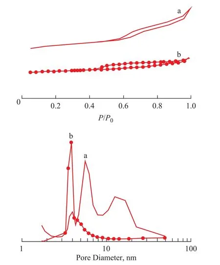
Figure 8 N2adsorption-desorption isotherms (upper) and pore size distribution (under) of samples:(a) catalyst, and (b) RCAT

Table 5 Product distribution of Catalyst and RCAT
To explore their catalytic performance, the catalyst was tested on its performance for cracking heavy crude oil, and the results were compared to those using RCAT. The results are listed in Table 5. As shown in Table 5, in comparison with RCAT, the catalyst exhibited a lower dry gas yield and coke yield, which might be partially ascribed to the presence of the mesopores, macropores and larger average pore diameter in the catalyst. The mesopores and macropores in the catalyst could accelerate the diffusionof the product molecules, and therefore, the secondary reactions leading to dry gas and coke formation were reduced. The microporous channels effectively connect the mesoporous channels to the macroporous channels in the catalyst and may decrease unwanted secondary reactions that lead to the formation of dry gas and coke[18-19]. The gasoline yield, conversion and liquid yields (LPG + gasoline + LCO) of the catalyst increased by 1.61, 0.77 and 0.72 percentage points, respectively, while maintaining a high bottoms upgrading selectivity.
The properties of the cracked gasoline are summarized in Table 6. In comparison with RCAT, the catalyst produced a reduction of 2.51 percentage points in olefins, and the research octane number and motor octane number of gasoline increased by 0.7 and 0.2 units, respectively.

Table 6 PONA analyses and gasoline octane number
4 Conclusions
In this study, the novel composite material with a wide pore distribution was synthesized by an in situ crystallization technique using the modified spent FCC catalyst. The FCC catalyst was then prepared using the composite material. The results indicated that the composite material contained Y zeolite with more micro-, meso- and macropores as well as high specific surface and pore volume. The as-prepared catalyst had a unique pore structure that was advantageous to the diffusion-controlled reactions, high surface area, moderate acidity, high activity, good hydrothermal stability and excellent vanadium and nickel passivation performance. Therefore, the catalyst exhibited excellent performance for heavy oil cracking along with a high selectivity for the gasoline yield and coke and dry gas yields.
Acknowledgements:Financial support was provided by the National Natural Science Foundation of China (No.21371055), the Hunan provincial Natural Science Foundation of China (No.11JJ2008), the Hunan provincial Colleges and Universities Innovation Platform Open Fund Project (No.15K049).
[1] Motaghed M, Mousavi S M, Rastegar S O, et al. Platinum and rhenium extraction from a spent refinery catalyst using Bacillus megaterium as a cyanogenic bacterium: Statistical modeling and process optimization[J]. Bioresource Technology, 2014, 171(11): 401-409
[2] Haragobinda S, Sradhanjali S, Kyle B, et al. An integrated sequential biological leaching process for enhanced recovery of metals from decoked spent petroleum refinery catalyst: A comparative study[J]. International Journal of Mineral Processing, 2015, 134(1): 66-73
[3] Leyva C, Ancheyta J, Mariey L, et al. Characterization study of NiMo/SiO2-Al2O3spent hydroprocessing catalysts for heavy oils[J]. Catal Today, 2014, 220–222: 89-96
[4] Guido Busca, Paola Riani, Gabriella Garbarino, et al. The state of nickel in spent fluid catalytic cracking catalysts[J]. Appl Catal A: Gen, 2014, 486(9): 176-186
[5] MarafiM, Stanislaus A. Spent hydroprocessing catalyst management: A review: Part II. Advances in metal recovery and safe disposal methods[J]. Resources, Conservation and Recycling, 2008, 53(1/2): 1-26
[6] Khalifa Al-Jabri, Mahad Baawain, Ramzi Taha, et al. Potential use of FCC spent catalyst as partial replacement of cement or sand in cement mortars[J]. Construction and Building Materials, 2014, 39(2): 77-81
[7] Meena Marafi, Antony Stanislaus. Studies on recycling and utilization of spent catalysts: Preparation of active hydrodemetallization catalyst compositions from spent residue hydroprocessing catalysts[J]. Appl Catal B: Environment, 2007, 71(3/4): 199-206
[8] Lin Y H, Yang M H. Chemical catalysed recycling of polypropylene over a spent FCC catalyst and various commercial cracking catalysts using TGA[J]. Thermochimica Acta, 2008, 470(1/2): 52-59
[9] Basaldella E I, Paladino J C, Solari M, et al. Exhaustedfluid catalytic cracking catalysts as raw materials for zeolite synthesis[J]. Appl Catal B: Environ, 2006, 66(3-4): 186-191
[10] Mitchell B R. Metal contamination of cracking catalysts. 1. Synthetic metals deposition on fresh catalysts[J]. Ind Eng Chem Prod Res Dev, 1980, 19(2): 209-213
[11] Önal M, Yilmaz H, Sarikaya Y. Some physicochemical properties of the white sepiolite known as pipestone from Eskişehir, Turkey[J]. Clays and Clay Minerals, 2008, 56(10): 511-519
[12] Hosseinpour N, Mortazavi Y, Bazyari A, et al. Synergetic effects of Y-zeolite and amorphous silica-alumina as main FCC catalyst components on triisopropylbenzene cracking and coke formation[J]. Fuel Process Technol, 2009, 90(2): 171-179
[13] Takeshige T, Kazuhiko U, Takami K. Vapor phase reaction of cyclohexanone oxime over boria modified HSZM-5 zeolites[J]. Canadian Journal of Chemical Engineering, 1991, 69(5): 1096-1099
[14] O’Sullivan P, Forni L, Hodnett B K. The role of acid site strength in the Beckmann rearrangement[J], Industrial & Engineering Chemistry Research. 2001, 40(6): 1471-1475
[15] Sun S H, Zheng S Q, Wang Z F, et al. Sulphur reduction additive prepared from caustic-modified kaolin[J]. Clay minerals, 2005, 40(4): 311-316
[16] Patrylak L, Likhnyovskyi R, Vypyraylenko V, et al. Adsorption properties of zeolite-containing microspheres and FCC catalysts based on Ukrainian kaolin[J]. Adsorp Sci Technol, 2001, 19(7): 525-540
[17] Zhang Jiexiao, Zhou Yan, Xu Yun, et al. Research and development of novel heavy oil catalytic cracking catalyst RCC-1[J]. China Petroleum Processing and Petrochemical Technology, 2014, 16(4): 7-11
[18] Miyazawa K, Inagaki S. Control of the microporosity within the pore walls of ordered mesoporous silica SBA-15[J]. Chemical Communications, 2000, (21): 2121-2122
[19] Gong Jianhong, Xu Youhao, Long Jun, et al. Synergetic effect of Y zeolite and ZSM-5 zeolite ratios on cracking, oligomerization and hydrogen transfer reactions[J]. China Petroleum Processing and Petrochemical Technology, 2014, 16(3): 1-9
LTAG Technology Passed Appraisal
Recently the LTAG technology combining selective hydro-saturation of LCO with selective catalytic cracking technology for producing high-octane gasoline or light aromatic hydrocarbons has passed technical appraisal.
This technology has creatively transformed the low-cost inferior light cycle oil (LCO) delivered from FCC unit to high-cost high-octane gasoline or light aromatics which can be used as chemical feedstocks to meet the refiners’urgent demand for enterprise restructuring and enhancing economic benefits, resulting in an apparent profitability. In recent years with the passenger cars being increasingly sold to many ordinary families, the demand for gasoline also increases abruptly along with a gradual shrinking diesel demand, which has forced the refiners to further reduce the diesel/gasoline ratio in their production plan. In the meantime, LCO, which is generally used as a diesel blending component, features low cetane number and high aromatic content, making itself a drug on the market.
In connection with the needs of the oil refinery, the technical personnel of the SINOPEC Research Institute of Petroleum Processing by means of molecular simulation and exploratory tests have developed the designated catalyst and the catalytic hydrotreating–catalytic cracking combination process to tackle the problem for utilization of LCO.
The said technology features a lot of flexible operating modes which have been applied in commercial scale at the SINOPEC Shijiazhuang Refining and Chemical Co., Ltd. to achieve the expected goals. In the case of the mode for separate processing of LCO, the gasoline yield can reach 60.55% with its research octane number equating to 96.4, and upon processing the resid commingled with LCO the gasoline yield can increase by 13—16 percentage points while the yield of LCO can be decreased by 15—20 percentage points, with the selectivity for gasoline from LCO equating to 79%—85%.
date: 2015-07-14; Accepted date: 2015-10-31.
Professor Zheng Shuqin, Telephone: +86-7308640122; E-mail: zhengshuqin37@163.com.
- 中国炼油与石油化工的其它文章
- Computational Fluid Dynamics Simulation of Liquid-Phase FCC Diesel Hydrotreating in Tubular Reactor
- Hydrothermal Liquefaction of Wheat Straw in Sub-critical Water/Ethanol with Ionic Liquid for Bio-oil Production
- Microbial Characterization of Denitrifying Sulfide Removal Sludge Using High-Throughput Amplicon Sequencing Method
- Promotional Effect of CoO(OH) on Selective Hydrogenation of Maleic Anhydride to γ-Butyrolactone over Supported Ruthenium Catalyst
- Quantitative Analysis Using Fourier Transform Ion Cyclotron Resonance Mass Spectrometry and Correlation between Mass Spectrometry Data and Sulfur Content of Crude Oils
- Design and Control of Self-Heat Recuperative Distillation Process for Separation of Close-Boiling Mixtures: n-Butanol and iso-Butanol