
Co-simulation and consumption analysis of wheel loader on negative loading condition
2015-10-29 07:15XudongYANJingYANGLongQUAN
机床与液压 2015年4期
Xu-dong YAN, Jing YANG, Long QUAN
(Key Lab of Advanced Transducers and Intelligent Control System, Ministry of Education and Shanxi Province,Taiyuan University of Technology, Taiyuan 030024,China)
Co-simulation and consumption analysis of wheel loader on negative loading condition
Xu-dong YAN, Jing YANG, Long QUAN*
(KeyLabofAdvancedTransducersandIntelligentControlSystem,MinistryofEducationandShanxiProvince,TaiyuanUniversityofTechnology,Taiyuan030024,China)
In order to analyze the energy consumption of wheel loader during working process, a three-dimensional (3D) model of wheel loader is established by Pro/E software, and it is imported into the software SimulationX to build the kinetic model of the whole wheel loader. Meanwhile, the simulation model of hydraulic system is built by the same software. By integrating the simulation model of hydraulic system with the kinetic model, the co-simulation model of wheel loader could be achieved. The precision of co-simulation model of the working device is verified through the comparison between simulation results and test results. The testing results show that, under negative loading condition, the energy loss in multi-way valve accounts for about 52%. The important energy loss in loader’s working hydraulic system using constant displacement pump is the large throttling loss of multi-way valves. This study provides a reference for designing of a more energy-efficient hydaulic system of wheel loader.
Wheel loader, Consumption analysis, Co-simulation, Negative loading
1 Introduction
As one of the most used machines in construction projects, wheel loader has the problems of high fuel consumption and serious emissions. Some relevant researches about the engine, converter, driveline[1-2] and stem heat balance technique [3-5] have been conducted to reduce energy consumption. As the significant part of the loader, the power of hydraulic system accounts for about 70% of the rated power of the engine. Currently, wheel loader’s hydraulic system generally uses constant displacement pump which is supposed to consume large energy, so it is important to improve the efficiency of hydraulic system. The existing system needs to be analyzed to accept the energy losses during operation.
Although some researches have been done to study the energy consumption of loader’s hydraulic system, these studies are short of quantified experimental results. Moreover, the studies about energy consumption of each part is discontinuous. For instance, Wang [6] and Zhang [7-8] conducted some researches about hydraulic system of wheel loader by using simulation software.
Firstly, the co-simulation model of wheel loader is established by using SimulationX software in this paper. The precision of co-simulation model of the working device could be verified through the comparison between simulation results and test results, and the energy consumption of the hydraulic system driving the working device in the work cycle is analyzed under negative loading condition. The research methods could be used for further research and comparisons for the operating characteristics and energy consumption of different hydraulic circuits, and it also can be used to guide the design of the hydraulic system and its practical operation.
2 Simulation analysis
The actions of insertion, spading and handling of wheel loader are achieved by means of the operation of working device. The common working device of wheel loader in domestic and foreign is six-bar linkage. The research object in this paper is a small wheel loader. The actual size of each part is surveyed and mapped firstly, including the bucket, boom, rocker, boom cylinder, linkage, et al. Moreover, three-dimensional geometric model of each parts is built and assembled based on their relative position and motion situation by Pro/E software. The three-dimensional geometric model of wheel loader is shown in Fig.1(a).
The hydraulic system of whole machine is given in Fig.1(b). Currently, the small type wheel loader usually adopts load sensing hydraulic steering system. The action of boom cylinder and rocker cylinder in wheel loader’s working device is controlled by multi-way valve block. The difficult point of multi-way valve is the relationship between the displacement of spool and the flow area of valve during modeling. So each part of multi-way valve is surveyed and mapped firstly. The geometry model of rocker control valve is shown in Fig.2(a). The type of throttling groove in valve core is U. The relationship between the displacement of spool and the flow area of valve is given in Fig.2(b).
The simulation study of steering and walking during working involves the model of tire-ground. In addition, due to the limitation of the built model, only the following operations will be studied in this paper: insert, bucket upturning, boom rising, bucket down, boom falling and bucket return.
The SimulationX software is an open platform, and it provides certain interfaces to connect with other software. Frist of all, the geometric model of wheel loader was converted into format of stl. Then, it can be introduced into SimulationX by CAD Import interface module. At last, the quality, moment of inertia and coordinate of centroid is set up. In addition, the multi-body kinetic model of wheel loader was built by setting the relative position between two connectors which are connected by revolute joint module. The kinetic model of wheel loader is given in sectionⅠof Fig.3.

1.bucket; 2.linkage; 3.rocker; 4.rocker cylinder; 5.front frame; 6. cab; 7. engine; 8. tank; 9.boom cylinder; 10. front axle; 11.boom
(a) Three-dimensional geometric model

1. pump;2.priority valve;3.steering gear; 4.load compensation valve; 5.steering cylinder; 6.boom cylinder; 7.rocker cylinder; 8.multi-way valve; 9.tank
(b) Principle diagram of hydraulic system
Fig.1 Geometric model and hydraulic system

(a) Geometry model

(b) Flow area of valve
Note: As shown in Fig.2, P and T represent the inlet port and outlet port of valve, respectively. A1 and B1 represent actuator port. P-T, P-B1, P-A1 represent the flow area when flow of oil run from P to T, P to B1, P to A1, respectively. A1-T and B1-T respectively represent flow area when flow of oil run from A1 to T, B1 to T.
Fig.2 Geometry model and flow area of rocker valve
The boom and rocker control valve model and the priority valve model can be connected with the pump and cylinder model by hydraulic tube model according to hydraulic system schematic. So, a complete hydraulic system model can be achieved. It is given in sectionⅡ of Fig.3. Finally, the kinetic model of wheel loader could be combined with hydraulic system model through hydraulic cylinder model. The co-simulation model of the working device is shown in Fig.3.
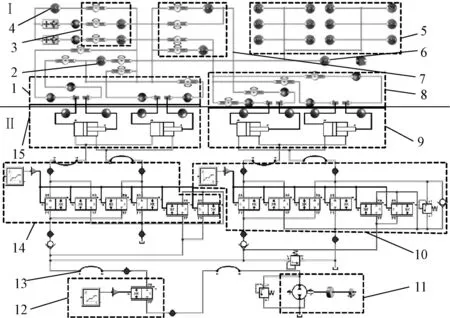
1,15.boom cylinder; 2.boom; 3.linkage; 4.bucket; 5.front frame; 6.cab; 7.rocker; 8,9. rocker cylinder; 10. rocker control valve; 11.constant displacement pump; 12. priority valve;13.tube; 14.boom control valve
Fig.3 Co-simulation model of wheel loader
All the forces acting on the working device in the course of work should be defined and calculated before the simulation. During one work cycle, the external force of wheel loader can be reduced toFx,FzandGw. Force analysis of wheel loader working device is given in Fig.4. The insertion resistanceFxcould be calculated by equation (1).
(1)
Where,Fxrepresents insertion resistance, N;K1represents coefficient of bulk and loose degree;K2represents coefficient of material density;K3represents coefficient of material height impact;K4represents coefficient of bucket shape;Brepresents bucket width,m;Lrepresents insertion depth of bucket, m.
The spading resistanceFzcould be calculated by equation (2)
(2)
Where,Fzrepresents spading resistance,N;BKrepresents bucket width,m;Lrepresents insertion depth of bucket, m;Kτrepresents shear resistance of material when bucket begin to rise, Pa.

Note: A, B, C, D, E, F, G, H,Irepresents hinge joints of working device;FC,FE,FHrepresents force in relevant hinge joints;LI,LHrepresents arm of force.Fx represents insertion resistance, N;Fz represents spading resistance,N.Gw represents gravity of materials, N;x,yrepresents horizontal distance and vertical distance between hinge joint I and the relieving, mm.
Fig.4 Force analysis of wheel loader working device
The curve of resistance on working device in the course of work are shown in Fig.5. All the above-mentioned forces will be loaded by body Force module in SimulationX software. The action point and direction of all forces can be set by position coordinates. The actual forces on working device can be simulated accurately finally.

Fig.5 Resistance of working device
3 Test analysis
The displacement sensor and pressure sensor are installed on wheel loader’s working device without changing its structure and performance. The instruments used during test process are mainly include: displacement sensor, pressure sensor and econ Type MI-7016 date acquisition analyzer. The displacement and pressure value of each cylinder, the pressure in pump outlet and inlet of multi-way valve are measured by the above sensors. The test pavement is concrete and the materials are massive sand and stone. The test is under negative loading condition: put 600 kg sand and stone on the bucket of loader and its centroid deviation from bucket’s center by 400 mm. The test of wheel loader typical condition is shown in Fig.6.
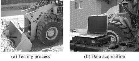
Fig.6 Test of wheel loader typical condition
4 Simulation and test results
The simulation and test results of each pressure detecting point under negative loading condition during continuous operation process is shown in Fig.7. It could be seen from this figure that at the period from 0.0 s to 2.5 s, the process of bucket upturning, pressure in rocker cylinder non rod side and pump outlet get increased. Moreover, there are some pressure fluctuations; at the period from 2.5 s to 3.5 s, the rocker control valve returns to neutral; at the period from 3.5 s to 9.3 s, the boom begins to ascend until unloading height. Due to interference action, rocker cylinder has a tendency to shrink which leads to the pressure in boom cylinder non rod side reach to 18 MPa. So, the load compensation valve starts unloading; at the period from 9.3 s to 11 s, the boom control valve returns to neutral; at the period from 11 s to 14 s, the bucket down and the operation of unloading has carried out; at the period from 14 s to 15 s, the rocker control valve returns to neutral; at the period from 15 s to 17.2 s, the process of bucket upturning and the bucket reaches to the initial position; at the period from 17.2 s to 18 s, the rocker control valve returns to neutral; at the period from 18 s to 22 s, the boom falls and the working cycle is over.

Fig.7 Simulation and test results under negative loading condition
5 Energy analysis
Since the test does not measure the pump outlet flow, the pump outlet powerPbwill be calculated by equation (3).
(3)
The powerPyconsumed by rocker cylinder during working process could be calculated by equation (4). While the power consumed by boom cylinder could be evaluated by the following equation (4).
(4)
Where,Pbrepresents output power of pump, kW;Pprepresents the outlet pressure of pump during working process, MPa;Ay,Adrepresent the high pressure chamber effective area of rocker and boom cylinder, mm2;VyandVdrepresent the speed of rocker and boom cylinder, respectively, mm/s, which could be obtained by the displacement of rocker cylinder during working process, kW;PBirepresents the pressure of the high pressure chamber, MPa;ABirepresents the effective area of the high pressure chamber, mm2;PAirepresents the pressure of the low pressure chamber, MPa;AAirepresents the effective area of the low pressure chamber, mm2;Virepresents speed of cylinder, mm/s.
The power change under unbalance loading condition is given in Fig.8. As shown in this figure, at the beginning of working, the power of pump is relatively small. During the process of bucket upturn, the power of pump gets increased and generates a large fluctuation. During the process of boom rising, the power of pump gets increased and generates fluctuation as well. However, during the process of boom failing, the power of pump is small.

Fig.8 Power change under unbalance loading condition
The output power of every element in hydraulic system could be calculated by using power integration module which is built in SimulationX. The testing results show that, under negative loading condition, the power of working device accounts for about 27% of the total output power of pump, energy loss in priority valve accounts for about 16% and energy loss in multi-way valve account for about 52%. The important energy loss in loader’s working hydraulic system using constant displacement pump is the large throttling loss of multi-way valve.
6 Conclusions
Energy consumption of each part in hydraulic system of working device has been studied in this paper by co-simulation and test analysis.
Under a negative loading condition, the power of working device accounts for about 27% of the total output power of pump, energy loss in priority valve accounts for about 16% and energy loss in multi-way valve’s export, import and its center position totally account for about 52%.
The important energy loss in loader’s working hydraulic system using constant displacement pump is the large throttling loss of multi-way valves. So, unloading losses could be eliminated if a load sensitive variable pump is used. This study could provide the basis for designing energy-efficient hydraulic control system of wheel loader.
Acknowledgement
This paper is supported by National Science and Technology Support Program(No.2014 BAF08B06).
[1]ZHAO Ding-xuan, ZHANG Zhi-wen, LI Tian-yu, et al. Fuzzy logic control strategy of series hybrid power loader[J]. Journal of Jilin University: Engineering and Technology Edition, 2014, 44(5): 1334-1341.
[2]CHANG Lü, LIU Yong-chen. Transmission ratio design of ZL50 loader based on working condition [J]. Transactions of the Chinese Society of Agricultural Engineering (Transactions of the CSAE), 2011, 27(2): 141-145.
[3]WANG Xue-lian, QIN Si-cheng, ZHAO Ke-li, et al. Operating heat characteristic analysis of wet drive axle on huge wheel loader[J]. China Journal of Highway and Transport, 2009, 22(2): 122-126.
[4]WANG Fei, QIN Si-cheng, ZHAO Ke-li. Numerical simulation study on wheel loader tube-fin radiator air flow and heat transfer character[J]. Journal of Jilin University: Engineering and Technology Edition, 2009(Supp.1): 196-199.
[5]WANG Jian-peng, QIN Si-cheng, ZHAO Ke-li, et al. Thermal balance of hydraulic system of a 50 type wheel loader [J]. Journal of Jilin University: Engineering and Technology Edition, 2009, 39(3): 652-656.
[6]WANG Kai. The working characteristics and energy consumption analysis of the 50 wheel loader’s hydraulic system [D]. Changchun: Jilin University, 2011.
[7]ZHANG Wei-wei, ZHOU Jun, ZHANG Yan-liang, et al. Energy- saving analysis in the hydraulic system of loader working device [J]. International Journal of Computer Applications in Technology, 2012, 45(2): 106-114.
[8]ZHANG Wei-wei. Kinetic modeling and consumption analysis of wheel loader working device [D]. Jinan: Shandong University, 2012.
10.3969/j.issn.1001-3881.2015.24.001 Document code: A
U415.51+4
装载机偏载工况工作过程联合仿真与试验
闫旭冬,杨敬,权龙*
太原理工大学 新型传感器与智能控制教育部与山西省重点实验室, 太原030024
为了分析装载机在偏载工作过程中的能量消耗情况,首先使用Pro/E软件建立了装载机工作装置的三维模型,将其导入SimulationX仿真软件中建立了装载机的动力学模型,同时使用该仿真软件建立了装载机工作装置液压系统模型,进一步建立了装载机联合仿真模型。然后对工作过程各个工作部件能量消耗情况进行了仿真和试验研究,通过比较仿真与试验结果,验证了所建立装载机工作装置机液联合仿真模型的准确性。结果表明:偏载工况下,多路阀的能量损失占52%;多路阀在一个工作循环中消耗能量最大,主要是中位卸荷损失。该研究为装载机液压控制系统节能设计提供了参考。
装载机;能耗分析;联合仿真;偏载
25 June 2015; revised 13 September 2015;
Long QUAN, Professor.
E-mail: quanlong@tyut.edu.cn
accepted 9 October 2015
Hydromechatronics Engineering
http://jdy.qks.cqut.edu.cn
E-mail: jdygcyw@126.com
猜你喜欢
体育科技文献通报(2022年4期)2022-10-21
体育科技文献通报(2022年3期)2022-05-23
支部建设(2021年18期)2021-08-20
发明与创新(2021年17期)2021-07-05
作文中学版(2020年1期)2020-11-25
重型机械(2020年2期)2020-07-24
意林(儿童绘本)(2020年1期)2020-02-14
石油化工建设(2018年2期)2018-07-11
凿岩机械气动工具(2016年2期)2016-11-11
现代企业(2015年5期)2015-02-28
- 机床与液压的其它文章
- Molecular dynamics study of the effects of tool geometric parameters on titanium nanometric cutting
- Research on active suspension control strategy based on fuzzy PID control
- The design of control system applied in artificial grass tufting machine adopting servomotors
- Influence of the underlap in the poppet valve on its performance
- Comprehensive reliability evaluation of foreign high-end gantry machining Center
- Analysis of contact stress on interference fitted surface of the train axle-bearing