
Molecular dynamics study of the effects of tool geometric parameters on titanium nanometric cutting
2015-10-29 07:15YingZHUYinchengZHANGJianyeGUOShunheQIZhiXIANG
机床与液压 2015年4期
Ying ZHU, Yin-cheng ZHANG, Jian-ye GUO, Shun-he QI, Zhi XIANG
(School of Mechanics Engineering, Shenyang Aerospace University, Shenyang 110136, China)
Molecular dynamics study of the effects of tool geometric parameters on titanium nanometric cutting
Ying ZHU, Yin-cheng ZHANG*, Jian-ye GUO, Shun-he QI, Zhi XIANG
(SchoolofMechanicsEngineering,ShenyangAerospaceUniversity,Shenyang110136,China)
A nanometric cutting model of titanium was built based on the basic principles of molecular dynamics (MD) method. EAM (embedded atom method) and Morse potential function were used, respectively, to compute the interactions between atoms. Effects and variations of different cutting edge radius and tool rake angle on surface morphology, system potential energy, cutting force and temperature of titanium workpiece in nanometric cutting process were analyzed. Results show that: When cutting with a bigger cutting edge radius, roughness of machined surface gets increased and the size of cutting force, temperature of workpiece and volume of chips will be decreased. Titanium atoms are suffered by compressive stress and shear stress when cutting with negative and positive rake angle, respectively. Positive rake angle is more conducive to cutting, and the sizes of tangential force and normal force also have significant changes under different tool rake angle.
Titanium, Molecular dynamics, Cutting edge radius, Tool rake angle, Nanometric cutting
1 Introduction
As one of the most important structural material in 21 Century, titanium has a series of advantages such as high specific strength, low density, high temperature resistant and corrosion-resistant, and it has become one of the key support materials in modern aerospace and national defense industry. Its sophisticated and high-tech products applied in aerospace and defense has the performance of high stability and high reliability [1].With the development of aeronautical manufacturing technology, there has a higher requirement for the processing precision of titanium and its alloy products, which has already approached to nanometer scale[2]. In the ultra-precision machining process of titanium and other metal or non-metallic materials, itneeds operate atoms in a spatial scale of 0.1-100 nm [3-4]. Machining process is essentially a discrete discontinuous phenomenon at atomic level, so it has very demanding requirement to the resolution of detecting instrument, precision of ultra-precision machine tool and cutting conditions. It is extremely difficult to study the mechanism of nanometric cutting through the experimental method. At the same time, theoretically, workpiece material is removed with discrete atoms or atomic layer. So the traditional cutting theories of macro cutting process, based on continuum mechanics and shear theory, are difficult to explain the various phenomena and internal mechanism in nanometric cutting process.The mature development of molecular dynamics simulation (MDS) provides a way to study precision/ultra-precision processing technology. MDS is a micro method to analyze solid model from the atomic point of view, through statistical physics method to calculate the motion of each molecule in simulation model, it can obtain the macroscopic properties of material [5-7]. In the field of nanofabrication, MDS provides a powerful tool and has been widely used for the study of micro nanometric cutting mechanism. Currently, typical research works include: with the MDS results, Yang et al. concluded that material removal mechanism in EDM can be explained in two ways: one by vaporization and the other by the bubble explosion of superheated metals. The forming mechanism of the bulge around discharge craters was also analyzed [8]. Pen et al. and Sun et al. achieved a multi-scale simulation of nanometric cutting processwith quasi continuum method [9-10]. Thiele and Melkote studied the influence of tool edge size and hardness on machined surface roughness and cutting force, and found the sharper the cutting edge, the more obvious the tool’s plowing action, which will increase the machined surface roughness and cutting force in each direction [11].Cai et al. proposed that in the plastic processing field of single crystal silicon, squeezing force is greater than cutting force. Tool cutting edge radius and cutting depth have a significant impact on the changes of material’s brittle-plastic transition [12]. Komanduri et al. studied the effects of negative rake angle of tool for single crystal copper nanometric cutting process, found that when negative rake angle reaches -76 °, there still have long continuous chips generated [13].
In contrast, the results of MDS and articles of titanium are relatively fewer. The study on ultra-precision machining and nanofabrication mechanism of this kind of material is relatively lagging behind. Because the geometric parameters of tool have a significant effect on machined surface quality and tool’s life, it is necessary to study its changes of the effect on nanometric cutting process [14-16]. At the same time, in view of the importance of titanium in the field of aerospace, this article, based on MD method, established the nanometric cutting model of titanium, mainly analyzed the effects of cutting edge radius and tool rake angle on the nanometric cutting process, and hope to provide some useful references for the future ultra-precision machining of titanium in aerospace manufacturing industry.
2 Experiment
2.1 Basic principle of MDS
Molecular dynamics is a microscopic method to analyze the characteristics of atomic and molecular solid model from the atomic point of view, it has been widely used in physics, materials science and mechanical processing and other fields, and becomes a powerful computer simulation method for the connection of microscopic and macroscopic worlds.The basic principleof MDS is to establish a particle system for the simulation of micro phenomenon. Forces between particles areobtained by the derivation of quantum mechanics potential energy function.For a large number of particles in a system that obeys the classical Newtonian mechanics laws,motion equations of particles are establishedby using classical Newtonian mechanics. The motion and trajectory of each particle in phase space areobtained by numerical solving motion equations that have built.Through the trajectory it can make a reasonable explanation to the process of material removing and surface formation.Correspondingly, the macro dynamic and static characteristicsof material could be derived by the use of statistical physics principles.
2.2 Simulation model
As shown in Fig.1, cutting model is composed by titanium workpiece and diamond tool. Workpiece material is in turn divided into Newton layer, thermostatic layer and boundary layer. Material of workpiece used in this model is close-packed hexagonal (HCP) structure titanium, whose crystal lattice constants in theory area=0.295 nm,c=0.468 nm. Material of tool selects diamond.

Fig.1 Nanometric cutting model of titanium MDS
Cutting parameters of simulation model are decided by computer’s hardware and software. In the simulation process, in order to ensure the temperature of thermostatic region constant, there need every 20 steps conduct a speed calibration to the atoms in thermostatic layer. In order to ensure the lattice symmetry and reduce boundary effects, fixed boundary condition is used, where the atoms in boundary layer are always stationary. Through different time step test, this article selects constant time step 2fs. System temperature is set 300 K, and (0100) cutting direction is adopted in simulation.
2.3 Potential function and interatomic force
Potential function of Ti-Ti selects EAM. The expression of total energyEof atomiis:
(1)
(2)
Where,Fiis the embedding energy of atomiwhose electron density isρi;ρiis the sum of electron cloud density produced by all other atoms’ extra nuclear electron to atomi;φijis the potential energy of atomiand atomj;rijis the distance between atomiand atomj;fj(rij) is the electron density produced by atomj.
The potential function of atoms between workpiece and tool chooses Morse potential function.
Standard Morse potential function form for Ti-Ti and C-C are:
(3)
(4)
The following similar Morse potential function is used to describe the interaction potential between Ti-C:
(5)
Where,φ(rij) is Morse potential function,αis gradient coefficient of potential energy curve andDis binding energy coefficient.
D,αand r between Ti, C and Ti-C have the following relationships:
(6)
(7)
(8)
Table 1 shows the Morse potential parameters between atoms.
Table 1 Morse potential parameters

Parametersα/nmD/eVr0/nmTi-Ti110.3110.2887C-C49.53.10.1240Ti-C22.830.9820.1892
Since diamond tool is much harder than titanium, it can be seen as a rigid body whose positions of atoms are considered to be fixed. So the potential function of C-C need not to be specified.
Interaction forces between atoms can be obtained by the derivation to atomic distance in potential function, according to the formula:
(9)
Where,F(rij) is the force between atom i and atomj,u(rij) is potential function between atomiand atomj.
u(rij) is substituted into formula (9) in the form of Morse potential. ThenF(rij) can be expressed as:
(10)
So atomic force of atomiis:
(11)
2.4 Relaxation process analysis
Potential energy curve are obtained after 5 000 time step relaxation for model. During the relaxation process, speed of atoms are calibrated every 20 time steps, and output every 100 time steps. Through the calculation results of speed and position for atoms, interatomic force and system potential energy could be obtained. From Fig.2, it can be seen that, system energy tends to a stable value from 4 000 step to 5 000 step, this indicates that system has entered a steady state and relaxation has completed at this time. After system reached dynamic balance, the potential energy of the system is calculated to be about -10 150 eV, which divided by 2 035, the total number of atomsin the system, then the average potential energy of each titanium atom could be obtained, which is -4.98 eV. The value is basically the same as ideal crystal binding energy value of metal titanium, which is 5.256 3 eV. So the accuracy of the present model could be verified.

Fig.2 Relaxation process of system potential energy
Relationship between temperature and kinetic energy could be expressed by the following formula:
(12)
3 Results and discussion
3.1 Effects of cutting edge radius
In traditional machining process, cutting thickness is much greaterthan tool edge radius, while in nano machining, cutting thickness is only a few nanometers. So the influence of tool edge radius cannot be ignored in nanofabrication. This section selects 3 groups of cutting edge radius for MDS to study the effects on cutting mechanism of metal titanium. Concrete cutting conditions are shown in Table 2.
Table 2 Cutting conditions of titanium nanometric cutting model

PotentialfunctionEAM(Ti-Ti) Morse(Ti-C)Workpieceatoms2035Toolatoms254,258,255Rakeangle0°Reliefangle5°Cuttingedgeradius0.712nm,1.068nm,1.424nmCuttingdepth2nmCuttingspeed300m/sCuttingplane(0001)Systemtemperature300KTimestep2.0fs
Fig.3 is the instantaneous images of atomic positions under different cutting edge radius in simulation process. It can be observed that, when the tool’s position is constant, with the increase of cutting edge radius, the number of amorphous atoms piled in front of tool and the volume of chips get decreased, while the number of deformed atoms near the tool nose gets increased. Due to the increasing number of squeezed titanium atoms near tool’s rear face, the thickness of metamorphic layer at machined surface increases, thus increase the surface roughness and decreasethe machined surface quality.

Fig.3 Instantaneous atomic positions under different cutting edge radius
Fig.4 and Fig.5 are the effects of different cutting edge radius on system potential energy and cutting force, respectively. It can be seen that with the increase of cutting edge radius, system potential energy and cutting forces show a trend of decrease. Reasons could be explained as follows: with the increase of cutting edge radius, the number of atomic lattices thatneed to be broken and the binding forces need to be overcome get decreased in the nanometric cutting process, which lead the decrease of system potential energy and cutting force. At the same time, squeezing action of tool’s rear facemakes the potential energy of some workpiece atoms storedin the deformed lattices, which will gradually restore theoriginal lattice structure when the tool goes by. That also contributed to the reduction of system potential energy.Fluctuations in change curve have a closerelationship with lattice reconstruction, lattice deformation and amorphous atoms’ formation. Meanwhile, the generation of chips also causes fluctuations to the cutting force.
Fig.6 is the effect of different cutting edge radius on workpiece temperature. As shown in the change curves, with the increase of cutting edge radius, temperature of workpiece decreases, which are similar with the variation of potential energy between titanium atoms. This is because the increase of cutting edge radius will reduce the number of deformed latticesand the energy released by them. As a result, the cutting temperature gets decreased. The cause of slight fluctuations in change curve is that thedeformation and reconstruction of atomic lattices are dynamic equilibrium process.The fluctuation rangegets decreased with the increase of distance, which is related to the squeezing extent of tool’s rear face.

Fig.4 Change curves of system potential energy under different cutting edge radius

Fig.5 Change curves of cutting force under different cutting edge radius

Fig.6 Change curves of workpiece temperature under different cutting edge radius
Simulation results show that, although the cutting edge radius are different, the process of removing material and surface formation are similar in the cutting process. This phenomenon indicates that cutting edge radius have no significant effects on the cutting mechanism. Meanwhile, the large cutting edge radius can reducecutting force and cutting temperature, and lead to poor quality of machined surface.
3.2 Effects of tool rake angle
Tool rake angle is a key factor in the geometry shape of tool, the changes of size will inevitably cause the changes of cutting force and morphology of workpiece, which will ultimately affect the quality of machined surface. This section selects three different rake angles to do the simulation. Concrete cutting conditions are shown in Table 3.
Table 3 Simulation parameters under the condition of different tool rake angles
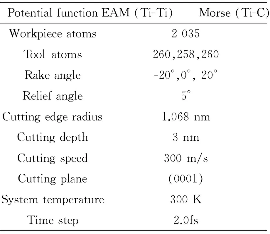
PotentialfunctionEAM(Ti-Ti) Morse(Ti-C)Workpieceatoms2035Toolatoms260,258,260Rakeangle-20°,0°,20°Reliefangle5°Cuttingedgeradius1.068nmCuttingdepth3nmCuttingspeed300m/sCuttingplane(0001)Systemtemperature300KTimestep2.0fs
Fig.7 is a set of images of instantaneous atomic positions under different tool rake angles in nanometric cutting process. Image of -20° rake angle shows that atoms in deformation region are mainly affected by the squeezing action, which cause metamorphic layer beneath the tool become thicker. Although the machined surface canproduce more elastic recovery due to the greater thickness of metamorphic layer, the final roughness of machined surface becomes greater. In addition, atoms in front of tool are mainly affected by squeezingaction, so the formation of chips is more difficult than the other two angles’, and the volume of chips is small. Image of 20° rake angle shows that atoms in deformation region are mainly affected by shear action, so the thickness of metamorphic layer below the tool becomessmaller. Since the machined surface can generate less elastic and plastic deformation, coupled with thesmaller thickness of metamorphic layer, the machined surface is smoothand the roughness is low. Accordingly, due to the atoms of workpiece ahead of the tool mainly affected by shear action, the formation of chips becomes easier than that of the other two angles, and thevolume of chips becomes relatively greater.Image of 0° rake angle shows atoms in deformation region are affected by squeezing and shear action so that the thickness of metamorphic layer and the volume of chips lie between the first two angles’.

Fig.7 Instantaneous atomic positions under different cutting edge radius
From the comparison of the simulation results, it could be found that tool rake angle has a greater impact onthe deformation of machined surface during nanometric cuttingprocess. With the increase of tool rake angle, the volume of chips gradually increases, so do the dislocations. While the deformation area of workpiece below the tool gets reduced, and the same as the roughness of machined surface.The greater the tool rake angle, the sharper the cutting edges of the tool and the easier the cutting process.
From Fig.8, it can be found that, when tool rake angle gets increased, tangential force and normal force will be decreased significantly. When tool cutting with a negative rake angle, the guiding role of tool’s rake face makes most of workpiece atoms gather below the tool, causing the intense extrusion of atoms between tool and machined surface. At this time, normal force plays a main role; when tool cutting the material with an equal or greater than zero rake angle, atoms near the rake face are affected by shear action obviously, so the tangential force plays a main role.It also can be observed that, with the increase of tool rake angle, normal force declining faster than tangential force, it could be explained that the guiding role of tool’s rake face makes the normal motion of chips move more briskly than its tangential motion, so the squeezing action in normal directionwill decline faster.

Fig.8 Change curves of cutting force under different tool rake angles
4 Conclusions
Combined with the ultra-precision machining background of metal titanium in aerospace field, this paper, based on the theoretical foundation of MD method, established MDS nanometric cutting model of metal titanium, and analyzedeffects of different geometric parameters of tool on cutting process, system potential energy, cutting force and cutting temperature. Main conclusions could be drawn as follows.
1) In the process of titanium nanometric cutting, a greatertool edge radius can make the number of squeezing titanium atoms increase near tool’s rear face, which lead a thicker deteriorative layer and lower machined surface quality. Meanwhile, bond energy between atoms can be more difficult to destroy, so the number of lattice deformation atoms gets decreased, which cause reduction ofpotential energy, cutting force and cutting temperature accordingly.
2) When cutting with negative rake angle, atoms in deformation region are mainly affected by squeezing action, and itwill eventually formthicker metamorphic layer. When cutting with positive rake angle,workpiece atoms are mainly suffered byshear stress in deformation zone, so the cutting process can be carried out more easily and obtain a better quality of machined surface. With the increase of tool rake angle from negative to positive, the sizes of tangential force and normal force have a decrease tendency. The leading role of normal force will be replaced by tangential force gradually.
Acknowledgements
This paper is supported by Science Foundation of AVIC I, Project(No. 2007ZE54011)
[1]Luo G Z, Zhou L, Den J. R & D of titanium in China[J]. Rare Metal Materialsand Engineering, 1997, 26(5): 1-6.
[2]Pramanik A. Problems and solutions in machining of titanium alloys[J]. International Journal of Advanced Manufacturing Technology, 2014, 70(5-8): 919-928.
[3]Zhang Q. Molecular dynamics simulation of tension on titanium[J]. Development and Application of Materials, 2011, 26(3): 4-7.
[4]Wang M H, Liu Z H, Wang H J, et al. Study on finite element simulation of surface residual stresses for precision machining titanium alloy TC4[J]. Manufacturing Automation, 2010, 32(11): 68-71.
[5]Uezaki K, Shimizu J, Zhou L B. Development of metal cutting process accompanied by a localized compressivehydrostatic stress field formation: Examination by molecular dynamics simulation[J]. Precision Engineering, 2014, 38(2): 371-378.
[6]Tanaka H, Shimada S. Atomic scale analyses of material behavior based on molecular dynamics simulation[J]. Journal of the Japan Society of Precision Engineering, 2010, 76(9): 1011-1014.
[7]Lin Z C, Chen Z D, Huang J C. Establishment of a cutting force model and study of the stress-strain distribution in nano-scale coppermaterial orthogonal cutting[J]. International Journal of Advanced Manufacturing Technology, 2007, 33(5-6): 425-435.
[8]Yang X D, Guo J W, Chen X F, et al. Molecular dynamics simulation of the material removal mechanism in micro-EDM[J]. Precision Engineering, 2011, 35(1): 51-57.
[9]Pen H M, Bai Q S, Liang Y C, et al. Multiscale simulation of nanometric cutting of single crystal copper-effect of different cutting speeds[J]. ActaMetallurgicaSinica (English Letters), 2009, 22(6): 440-446.
[10]Sun X Z, Chen S J, Cheng K, et al. Multiscale simulation on nanometric cutting of single crystal copper[J]. Proceedingsofthe Institutionof Mechanical Engineers Part B-Journalof Engineering Manufacture, 2006, 220(7): 1217-1222.
[11]Thiele J D, N Melkote S. Effect of cutting edge geometry and workpiece hardness on surface generation in the finish hard turning of AISI52100 steel[J]. Journalof Materials Processing Technology, 1999, 94(2): 216-226.
[12]Cai M B, Li X P, Rahman M. Study of the mechanism of nanoscale ductile mode cutting of silicon using molecular dynamics simulation[J].International Journal of Machine Tools and Manufacture, 2007, 47(1): 75-80.
[13]Komanduri R, Chandrasekaran N, Raff LM. Some aspects of machining with negative-rake tools simulating grinding: a moleculardynamics simulation approach[J]. Philosophical Magazine B, 1999, 79(7): 955-968.
[14]Muhammad A, Osamu O, Hiromichi O. Advanced burr-free hole machining using newly developed micro compound tool[J]. International Journal of Precision Engineering and Manufacturing, 2012, 13(6): 947-953.
[15]Zheng G M, Zhao J, Zhou Y H, et al. Performance of graded nano-composite ceramic tools in ultra-high-speed milling ofinconel 718[J]. International Journal of Advanced Manufacturing Technology, 2013, 67(9-12): 2799-2810.
[16]Ku T W, Kang B S. Tool design and experimental verification for multi-stage cold forging process of the outer race[J]. International Journal of Precision Engineering and Manufacturing, 2014, 15(9): 1995-2004.
10.3969/j.issn.1001-3881.2015.24.009 Document code: A
TG501.1
刀具几何参数对金属钛纳米切削影响的分子动力学研究
朱瑛,张银成*,郭建烨,齐顺河,向智
沈阳航空航天大学 机电工程学院, 沈阳110136
基于分子动力学的基本原理,构建了钛的纳米切削分子动力学仿真模型。工件原子间采用嵌入原子势EAM(Embedded atom method),工件原子与刀具原子间采用Morse势函数,研究了在不同刃口半径和刀具前角条件下,钛纳米切削过程中工件形态、系统势能、切削力以及工件温度等的变化规律。结果表明:随着刀具刃口半径增大,加工表面粗糙度增加,切削力和工件温度降低,切屑变薄;当刀具前角由负值增加到正值,钛工件承受的压应力逐渐变为剪应力,正前角刀具更有利于切削,同时在不同的刀具前角下,切向力和法向力的大小也有显著变化。
钛;分子动力学;刃口半径;刀具前角;纳米切削
1 September 2014; revised 22 December 2014;
Yin-cheng ZHANG. E-mail:zhyc52180@163.com
accepted 6 March 2015
Hydromechatronics Engineering
http://jdy.qks.cqut.edu.cn
E-mail: jdygcyw@126.com
猜你喜欢
金刚石与磨料磨具工程(2021年5期)2021-11-06
制造技术与机床(2019年9期)2019-09-10
物理学报(2018年23期)2018-12-14
制造技术与机床(2018年10期)2018-10-13
物理学报(2018年7期)2018-05-03
制造技术与机床(2017年7期)2018-01-19
辽宁科技大学学报(2017年6期)2017-04-10
山东工业技术(2016年15期)2016-12-01
中国有色金属学报(2015年6期)2015-03-18
组合机床与自动化加工技术(2014年12期)2014-03-01

- 机床与液压的其它文章
- The design of control system applied in artificial grass tufting machine adopting servomotors
- Research on active suspension control strategy based on fuzzy PID control
- Automobile magnetorheological damper multi-objective optimization analysis
- Co-simulation and consumption analysis of wheel loader on negative loading condition
- Influence of the underlap in the poppet valve on its performance
- Comprehensive reliability evaluation of foreign high-end gantry machining Center