
Mathematic modeling method for addendum line of spiral bevel Gear
2015-11-03 07:02XiaoqiangWUChunyouZHANG
机床与液压 2015年3期
Xiao-qiang WU, Chun-you ZHANG
(College of Mechanical Engineering, Inner Mongolia University for the Nationalities, Tongliao 028000, China)
Mathematic modeling method for addendum line of spiral bevel Gear
Xiao-qiang WU, Chun-you ZHANG*
(College of Mechanical Engineering, Inner Mongolia University for the Nationalities, Tongliao 028000, China)
During the process of spiral bevel gear addendum chamfering, the cutter moves material according to a certain trajectory and this process must first determine the mathematical model of tooth top line. Based on the tooth surface of spiral bevel gear processing principle, this paper established the mathematical model of tooth surface for spiral bevel gear, and then, with gears outside the cone surface equation according to the curved surface intersection method to get the mathematical model of the tooth top line, for the spiral bevel gear addendum chamfering processing to provide theoretical support.
Spiral bevel gear, Addendum, Surface intersection
1 Introduction
Gear transmission is one of the most important form of mechanical transmission, and this form is also the most widely used transmission form [1]. Due to the advantages such as high bearing capacity and stable transmission, spiral bevel gear is widely used for the mechanical transmission of agricultural machinery, ship, precision instrument, construction machinery and vehicle [2]. In order to make spiral bevel gear smooth drive, lower noise and improve the life of the gear, the addendum of spiral bevel gear needs to chamfer. The machining process is to grid the wheel motions according to a certain trajectory to complete chamfering machining. In order to complete the above machining proces, the machine parameters are very important. Since the calculation of machine parameters have the tightness contraction with the mathematical model. Therefore, the building method of addendum line mathematical model of spiral bevel gear is given.
Firstly, from the machining principle of spiral bevel gear tooth surface, the motion trajectory of inner and outer blades’ cutting edge is regard as the mathematical model of tooth surface. Then, the mathematical model of addendum line could be obtained according to the method surface intersection with the conical surface. This paper could provide the theoretical support for the addendum chamfering processing.
2 The equation of addendum conical surface
The all addendum lines of spiral bevel gear are located at the same conical surface, and the conical surface is shown in Fig.1. The calculation coordinate system is built to obtain the equation of conical surface. The origin coincides with the center of big end conic section, the axiszcoincides with the work piece axis, and the direction is from the big end to the small end. The axisxis located at the horizontal direction, the direction is outward along the center of the circle. The axisycould be determined through the right-hand rule. The coordinate of any point on the conical surface at the calculation coordinate system is the equation of addendum conical surface. The equation could be expressed as follows:
(1)
Where,ρandtare the two parameters of addendum conical surface,δais addendum conic angel of spiral bevel gear.
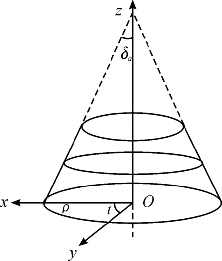
Fig.1 Calculation coordinate system of addendum conical surface equation
3 Model of spiral bevel gear tooth sur-face
As shown in Fig.2, in the process of cycloid spiral bevel gear, the thought of shape wheel is adopted. Cutter rotates and revolutes with the cradle at the same time, the motion trajectory of blades are the tooth profile of imaginary plane shape wheel, corresponding process of the concave and convex tooth surface for workpiece. The extended epicycloid tooth formation process along the long direction is shown in Fig.3 on the indexing plane of shape wheel. The machining process could be seen as two gear of imaginary shape wheel and the workpiece meshing process. Due to the actual process, the movement of shape wheel could be obtained by the cutting wheel rotation and the revolution of the cradle, and then, it is coupled with the rotation of workpiece, the cycloid bevel gear generating cutting is realized.
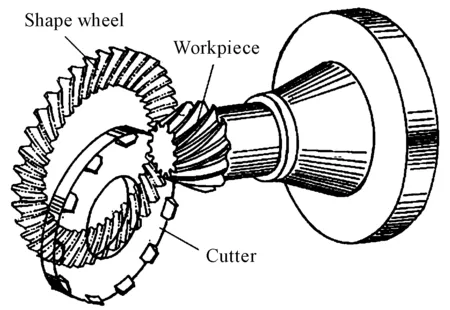
Fig.2 Machining principle of cycloid bevel gear
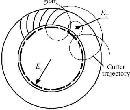
Fig.3 Generation of extended epicycloid
The generation of shape wheel tooth surface is shown in the Fig.4. The levorotation gear uses the levorotation cutter to machining, and the point is the intersection point between the cradle axis and the workpiece axis. Then, the cutter and workpiece rotate along the direction of anticlockwise, and the cradle rotates along the direction of clockwise. The motion trajectory of cutting edge is the dextral shape wheel tooth surface. According to the above analysis, the generation of dextral shape wheel tooth surface could be seen that the point on the cutter edge at the indexing plane of shape wheel generates the extended epicycloid when the cutter rotates around itself axis and revolute with the cradle at the same time, and the cutter edge generates the extended epicycloid ruled surface [3-5]. The ruled surface is the dextral shape wheel shape surface, and the equation can be expressed as in the reference [6]
(2)
Where,
x=r0cos(wC+Shδ0)+ShExsin[wC-
The Eq.(2) can be used for the levorotation and the dextral spiral bevel gear. When machining the levorotation gear,Sh=1, and when machining the dextral gear,Sh=-1,wc=Sh[90°-βm+(1+ibd·w)], the pressure angle of cutter isαk, the inner cutter is positive value and the outer cutter is negative value,uis the distance between the reference pointMto the pointQalong the direction cutter edge to the cutter top,wis the cutter rotation angle.
According to the motion condition of conjugate surface contiguous and meshing theory, the meshing condition equation of shape surface and tooth surface could be obtained. And the equation [7] of gear tooth surface at the workpiece coordinate system can be expressed as follows:
(3)
Where,Mis coordinate transformation matrix,φis the rotation angle of shape wheel,AandBare the meshing point coordinates through the meshing condition.
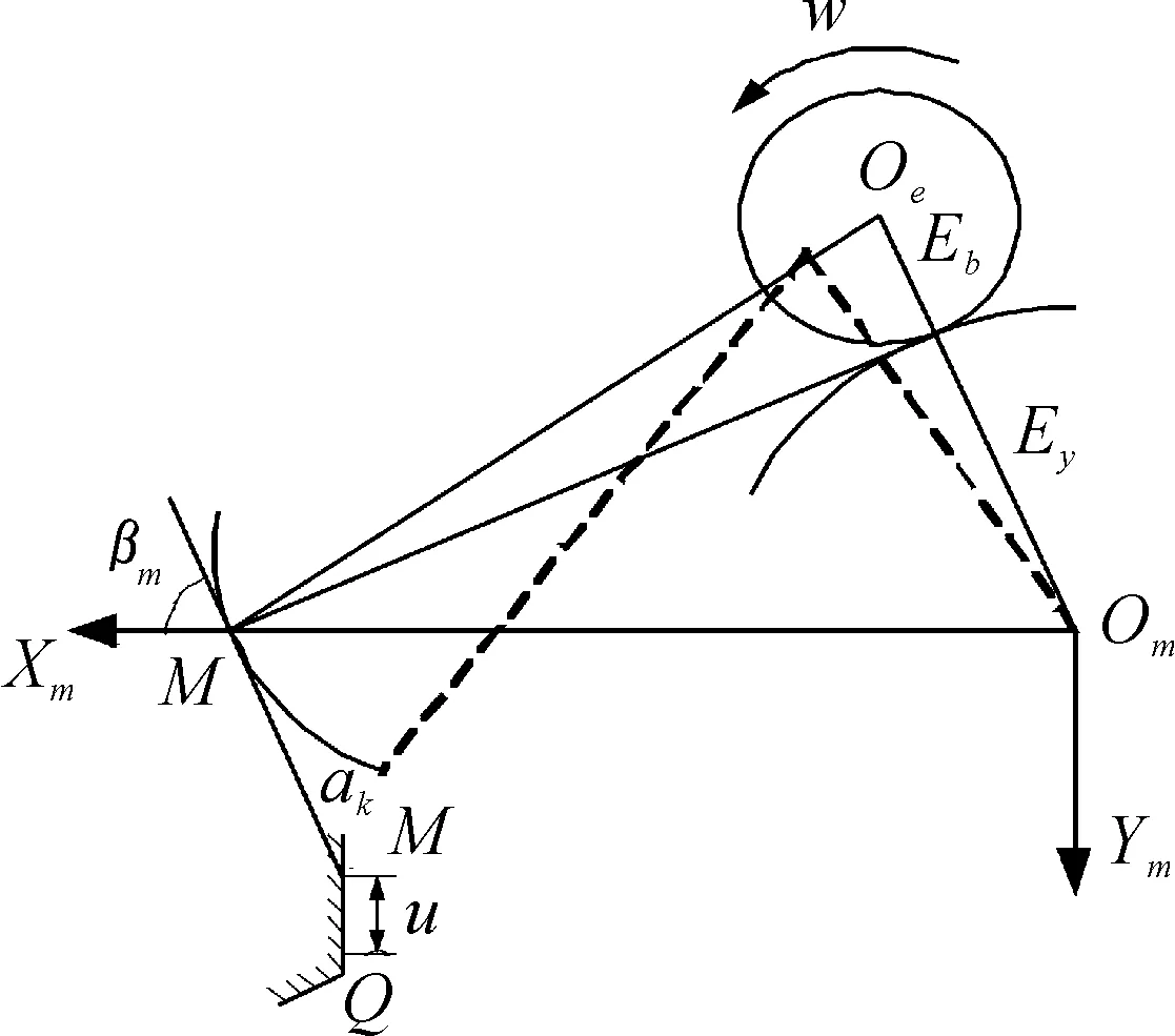
Fig.4 Generation process of shap wheel tooth
4 Calculation method of addendum line
Due to the complexity tooth surface equation, the intersection line of the two surfaces will be difficult to obtain if the analytical method is directly adopted. Thus, this paper will use the method of surface intersection to obtain the addendum line.
The surface intersection [8-9] is the key technology of CAD/CAM, and the technology is widely used in the process of surface design and surface machining. Since the expression forms of surface have the implicit expression and the parameter equation, the ordinary problems of surface intersection could be concluded by three conditions that they are the intersection problem between implicit expression and implicit expression, the intersection problem between implicit expression and parameter and the intersection problem between parameter and parameter.
The method for intersection between free parameters surface could roughly include the following several kinds: algebraic method, discrete grid method, discrete segmentation method, iterative method and tracking method. Where, algebraic method adopts the intersection of low-order surface. Discrete grid method is similar to the discrete segmentation method, and both of them use the patch to instead of the intersection line of curved surface. These methods have poor accuracy, and often are used in combination with other methods. The main idea of tracking method is that under the premise of known surface intersection point, this point is seen as the starting point, and the next intersection point is searched along the intersection line direction. The above process is repeated until all the intersection points are found. Iterative method has the advantage of fast speed and calculation precision. Under the condition of appropriate initial value selection, the calculation precision will be improved nearly ten thousand times through a couple of iterative times. And the essence is that the initial value of intersection line could be calculated by repeatedly iterative, and the precision intersection point is obtained. The low accuracy initial point is firstly obtained by the discrete grid method in this paper. Then, the higher accuracy starting point of addendum line is obtained by iterative method. Finally, the intersection line between the spiral bevel gear tooth surface and the conical surface of gear is obtained by the improved Euler method.
The addendum line is the intersection line between the spiral bevel gear tooth surface expressed by the Eq.(3) and the addendum conical surface expressed by the Eq.(1). For the convenience of expression, the tooth surface can be expressed as
(4)
The addendum conical surface can be expressed as
(5)
The addendum line meets the Eqs.(4) and the Eqs.(5), and it meets the following equation as well.

(6)
So, the equation can use the parameter form to express as:
(7)
The low accuracy initial point of addendum line is the pointGby the discrete grid method. The corresponding point of the pointGon the tooth surface and the addendum conical surface are respectivelyG1=P(u0,w0) andG2=Q(ρ0,t0). Due to the low accuracy of the pointG, thus,G1can not coincide withG2. Assumingρ0as the fixed parameters, the group of parametersu,w,tcould be obtained. The parameters have the following relationships:
(8)
The Eq.(8) is nonlinear equations, the parameter of intersection points of two surface are the solution of this equations. As shown in Fig. 5, the iterative method of Netwon is adopted. The iterative increment Δu, Δwand Δtare obtained by the Eq.(9).
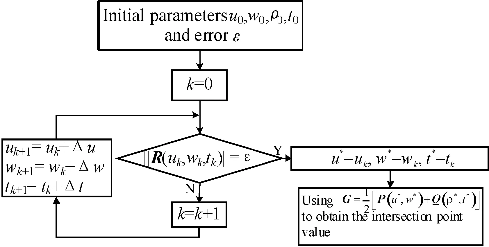
Fig.5 Process of iterative method
(9)
Where,J(uk,wk,tk) is Jacobia iterative matrix, and it can be expressed as
The starting point of addendum line is obtained by the above method. Then, the other points of addendum lines will be obtained by using the improved yura method, and the iterative process is as follows:
Prediction
(10)
Where,his iterative step, and it can be confirmed by the intersection precision.
Correction
(11)
Then, the coordinates of point on the addendum line can be expressed as
(12)
The numerical solutions of addendum line can be obtained through the above method of intersection surface. As shown in Fig.6, the addendum lines can be plotted according to the numerical solutions of addendum line.
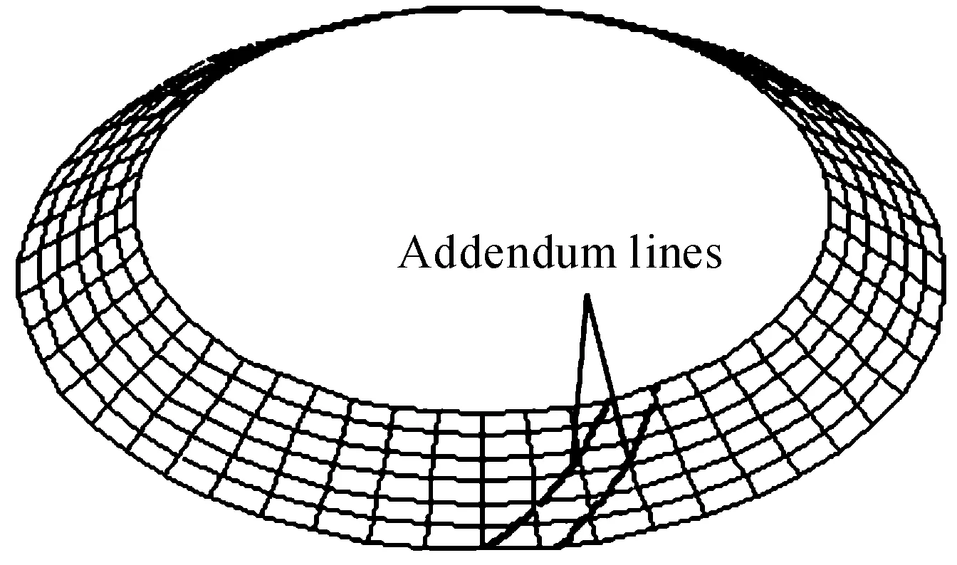
Fig.6 Addendum lines
5 Conclusions
This paper presents a mathematical modelling method of spiral bevel gear addendum line. From the machining principle of spiral bevel gear, the imaginary shape wheel tooth surface expressed by the motion trajectory could be seen as the equation of spiral bevel gear tooth surface. Then, the numerical solutions of addendum line are obtained by using the addendum conical surface according to the surface intersection method. The proposed method provides theoretical support for the addendum chamfering processing.
Acknowledgement
This paper is supported by National Natural Science Foundation of China (No.6144041).
[1]Zhang Ce. Mechanical Principle and Mechanical Design[M]. Beijing: China Machine Press, 2004.
[2]Han Weina. Research on the Method of Addendum Lines’ Chamfering for Driven Gear in Spiral Bevel Gear Pair[D].Tianjin: Tianjin University, 2007.
[3]Cai Guoliang, Li Yuxiu, Wang Shihuan. Property of Ruled Surface and Its Application in Engineering[J]. Mathematics in Practice and Theory,2008,38(8): 98-102.
[4]Sprott K, Ravani B. Kinematic Generation of Ruled Surfaces[J]. Advances in Computational Mathematics 2002, 17: 115-133.
[5]Schaaf J A, Ravani B. Geometric Continuity of Ruled Surfaces[J]. Computer Aided Geometric Design, 1998,15: 289-310.
[6]Li Wei, Li Jianfeng, Wang Qingyun. Tooth Face Equations and Graph Emulation of Klingelnberg Cyclo-palloid Spiral Beve Gears[J]. Mechanical Science and Technology, 2006, 25(12): 1462-1466.
[7]Gao Xiaoping. Foundational Process Technology Research on Milling Klingelnberg Cycloid Sprial Bevel Gear[D]. Tianjin: Tianjin University, 2009.
[8]Mo Rong, Chang Zhiyong. Computer aided geometric modeling technology[M]. Beijing: Science Press, 2009:122-132.
[9]Shi Fazhong. Computer aided geometric design and non-uniform rational b-spline (CAGD&NURBS)[M]. Beijing: Beijing University of Aeronautics and Astronautics Press, 1994.
(Continued from 25 page)
[8]Min Zuojian.Hydraulic and pneumatic transmission[M].Beijing: Mechanical industry press, 2009: 53-56.
[9]Pu Cengkun.The Pilot Stage Allocation and ControlStrategy Research of Large-Flow RateElectro-Hydraulic Cartridge Servo-Valve [D].Hangzhou: Zhejiang University, 2013.
[10]Peng Xiwei.Design of Comprehensive performance testing device for hydraulic cylinder [J].Chinese Hydraulics and Pneumatics, 2011(11): 93-94.
摘要:根据液压缸的试验标准和现有液压缸试验台的不足,针对大型液压缸试验台要求高压、大流量的特点,设计出基于插装阀的液压缸试验台,并考虑到设计方便及经济型要求,提出加载液压缸和被测液压缸采用同一个液压源、高压系统和大流量系统并联的方案,减少了电机以及液压泵的使用数量,减小了系统功率,设计出一套自动化程度高,制造成本低,节能的液压缸试验台系统。
关键词:液压缸试验台; 高压; 大流量; 插装阀; 自动化
螺旋锥齿轮齿顶线数学建模方法
吴晓强, 张春友*
内蒙古民族大学 机械工程学院, 内蒙古 通辽028000
在螺旋锥齿轮齿顶倒棱加工中,刀具按照一定的轨迹运动,首先要明确齿顶线的数学模型。从螺旋锥齿轮齿面的加工原理出发,得到了螺旋锥齿轮齿面的数学模型,然后与齿轮外圆锥面方程按照曲面求交的方法得到了齿顶线的数学模型,为螺旋锥齿轮齿顶倒棱加工提供理论支撑。
螺旋锥齿轮;齿顶线;曲面求交
基于插装阀的液压缸试验台设计
冯开林,马官国*,郭笑笑,左福涛,江守雷
山东科技大学,山东 青岛266590
8 January 2015; revised 26 April 2015;
Chun-you ZHANG,
E-mail: wangzai8402@163.com
10.3969/j.issn.1001-3881.2015.18.005 Document code: A
TH215
accepted 17 June 2015
Xiao-qiang WU, Ph.D., Lecture.
Hydromechatronics Engineering
http://jdy.qks.cqut.edu.cn
E-mail: jdygcyw@126.com
猜你喜欢
能源工程(2021年5期)2021-11-20
廉政瞭望(2018年15期)2018-09-17
中国市场(2016年36期)2016-10-19
科技视界(2016年20期)2016-09-29
科技视界(2016年20期)2016-09-29
专用汽车(2015年7期)2015-03-01
河南科技(2014年24期)2014-02-27
河南科技(2014年16期)2014-02-27
小哥白尼·趣味科学画报(2006年16期)2006-05-29

- 机床与液压的其它文章
- Design and simulation of the hardware in the loop simulation platform for vehicle ACC system
- A research on film thickness of a typical dynamic seal for hydraulic actuators
- Research on flexible manufacturing system real-time scheduling optimization
- The design of the hydraulic cylinder test bed based on cartridge valves
- Numerical simulation on the aerodynamic performance of ice coating airfoil of wind turbine blade
- Manufacturing of self-lubricating diamond tools with Ni-Cr alloy adding with Ni/C