
Vibration response analysis of a lathe spindle by using the ANSYS finite element method
2015-11-03 07:08ZexinZHOU
机床与液压 2015年3期
Ze-xin ZHOU
(School of Energy and Power Engineering, Wuhan University of Technology, Wuhan 430063, China)
Vibration response analysis of a lathe spindle by using the ANSYS finite element method
Ze-xin ZHOU*
(School of Energy and Power Engineering, Wuhan University of Technology, Wuhan 430063, China)
Making an analysis for vibration modal and frequency response of the lathe spindle, respectively by using finite element method based on ANSYS and experiment of CA6140 type lathe in machining, and the calculation results are compared and analyzed, which verified the accuracy of ANSYS method. Numerical simulation and experimental results show that: Spindle in the first order and fifth order are prone to resonance, but did not reach resonance, the low order natural frequency have more effect than the high order natural frequency of the spindle vibration; by the experiments can conclude that the maximum vibration of the main shaft in the working state is mainly concentrated in the vicinity of its two ends, therefore, the improved bearing is an important way to reduce the vibration of the main shaft and ensure the machining accuracy, and the research results can provide a theoretical reference for the structural optimization design of the lathe.
ANSYS FEM, Lathe spindle, Modal analysis, Harmonic response analysis, Resonance
1 Introduction
With the rapid development of mechanical processing in high speed, high precision and high flexibility, and in addition to the requirements for machine tool have features that light quality, low cost, easy to use and also has a good process performance, and calls for machine tools has become more and more high processing performance. We all know that the dynamic characteristic is the most important performance index of the evaluation of machine tools [1]. But most design of ordinary lathe follows the usual concept, the theory basis of machine tool design deficiencies [2]. In the component part of the whole machine tool, the spindle is an important part, which drives the rotation of the chuck and work piece, and in the process of turning processing, often have a strong vibration between work piece and tool, damage and interfere with the normal cutting processing, which is a very harmful phenomenon. When the lathe vibrates, the surface quality of work piece is deteriorated, and it has obvious surface marks, which increasing the roughness of the work piece, at this time must be reduced to the working efficiency of the lathe greatly. When the lathe Strong vibrates, can cause collapse edge phenomenon, and make the machining process cannot continue. Due to the vibration, will make the lathe and the tool wear and to shorten the lathe and the cutting tool service life. At the same time vibration is also accompanied by the noise, making harms to workers health of body and mind, and making work environment deterioration. Lathe vibrations can be classified into three kinds, which are free vibration, forced vibration and the Self system vibration, according to estimates that of vibration is respectively 5%, 30%, 65% [3-4]. Since the free vibration, which motor driving occupies a large part of the main shaft vibration, so the dynamic analysis of the main shaft is necessary. In this paper, we making an analysis for vibration modal and harmonic response of the lathe spindle based on ANSYS finite element method of CA6140 type lathe in machining and its technical parameters as shown in Table 1, through the research of the natural frequency, vibration mode, harmonic response and other dynamics research to provide a reference for optimization design of this type machine tool.
Table 1 Main technical parameters of CA6140 lathe
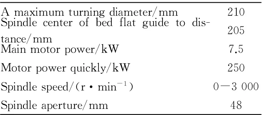
Amaximumturningdiameter/mm210Spindlecenterofbedflatguidetodis-tance/mm205Mainmotorpower/kW7.5Motorpowerquickly/kW250Spindlespeed/(r·min-1)0-3000Spindleaperture/mm48
2 Theoretical analysis
2.1 The foundation theory of modal analysis
Any deformable object has the inherent frequency and the vibration mode, and they are the important parameters in the structure design under the dynamic load. The main purpose of the modal analysis is to determine the vibration characteristics of the structure, i.e., the natural frequency, the vibration mode and the mode participation coefficient of vibration (the degree of vibration in a particular direction), importantly they are the frequency feature points of the structure that produce resonance. Calculating modal analysis based on the geometric features of the mechanical structure and material properties such as the original parameters, form the system of discrete mathematical model with finite element method-mass matrix and stiffness matrix, and then by solving eigenvalue problem to determine the modal parameters of the system [5]. Undamped modal analysis is a classical eigenvalue problem, the dynamics equations of motion can be described as:

(1)
Where:[M] is mass matrix;[K] is stiffness matrix.
The free vibration of Structural is harmonic vibration, the displacement of sine function can be described as:
(2)
Taking (2) into (1) :
(3)

Modalanalysisactuallyissolvingtheeigenvalueandeigenvector,andthroughthemodalanalysiscandeterminethemodelorthevibrationofthestructurecharacteristics,andcanalsogetthemodelofnaturalfrequencies,modeshapesandmodalparticipationfactor(inaparticulardirectionvibrationmodetheextenttowhichinvolvedinthevibration).
2.2Thefoundationtheoryofharmonicresponse
Anycontinuousperiodicloadwillgenerateacontinuousperiodicresponseinthesystem,i.e.,theharmonicresponse,harmonicresponseanalysisisalsoknownasthefrequencyresponse,whichismainlyanalysisthesteadystateresponseoflinearstructureinunderharmonicload(withtimeregularchangeinharmonicload).Themainpurposeoftheanalysisistogetthestructureresponsecurveinseveralfrequencies,undertheharmonicload,andfoundthepeakresponseofthestructure,sothestressresponseofthestructureisfurtherobserved[6].Theharmonicresponseanalysisislinearwhichonlycalculatestheresponseofthestructuretotheforcedvibration,withoutconsideringthetransientvibrationatthestartoftheexcitation.Harmonicresponseanalysisofthemainaimistoensurethatthedesignofthestructurecanwithstandavarietyofdifferentfrequencyharmonicload,detectingstructuralresonantresponse,andtoavoidresonancewhennecessary.
Theharmonicresponseanalysisisthevibrationresponseofthestructurewhentheexternalforceformistheharmonicfunction(i.e.thefunctionformissinorcos),theexpressionis[7]


(4)
Where:

Where:
Fmax—Load amplitude;ψ—Phase angle of load function;F1=Fmaxcosψ;F2=Fmaxsinψ;
Dmax—Displacement amplitude;D1=Dmaxcosψ;D2=Dmaxsinψ;
Taking (5)and (6)into(3)can get the equations of motion for harmonic analysis.
(7)
To solve the harmonic motion equation (7), there are two methods, one is a complete method, the other is a modal superposition method.
In ANSYS, using the complete method is a default method, using complete structural matrix, and allows the asymmetric matrix.
In the complete method, the matrix equation is directly solved in the nodal coordinate system, except for the use of the complex number, which is similar to the linear static analysis.
Order:
(8)
There is
(9)
3 The ANSYS finite element analysis
3.1 Modeling and material properties
In the environment of Solidworks, according to the similarity theory, the model of the lathe spindle is simplified as shown in Fig.1 (a), main shaft length is 870 mm, and the length is divided into eight parts, the diameter is 80-195 mm, central hole of spindle is 48 mm, Sectional view of the model is shown in Fig.1 (b).

Fig.1 3 d model of Main shaft
According to the actual lathe spindle material model entity set to 45 steel, the performance of the material parameters are shown in Table 2.
Figures are the density, Poisson’s ratio and Young’s modulus of 45 steel with temperature variation, we can find that it is not affected by temperature.
Table 2 Material parameters of 45 steel
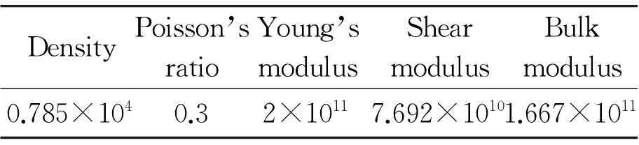
DensityPoisson’sratioYoung’smodulusShearmodulusBulkmodulus0.785×1040.32×10117.692×10101.667×1011
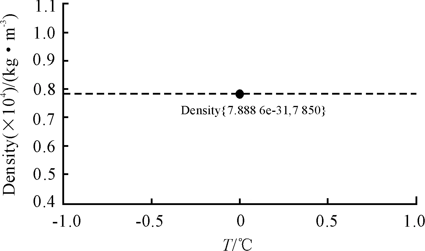
Fig.2 Density with the temperature variation
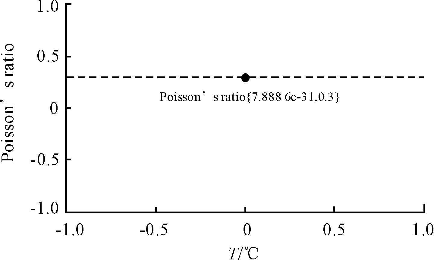
Fig.3 Poisson’s ratio with the temperature variation
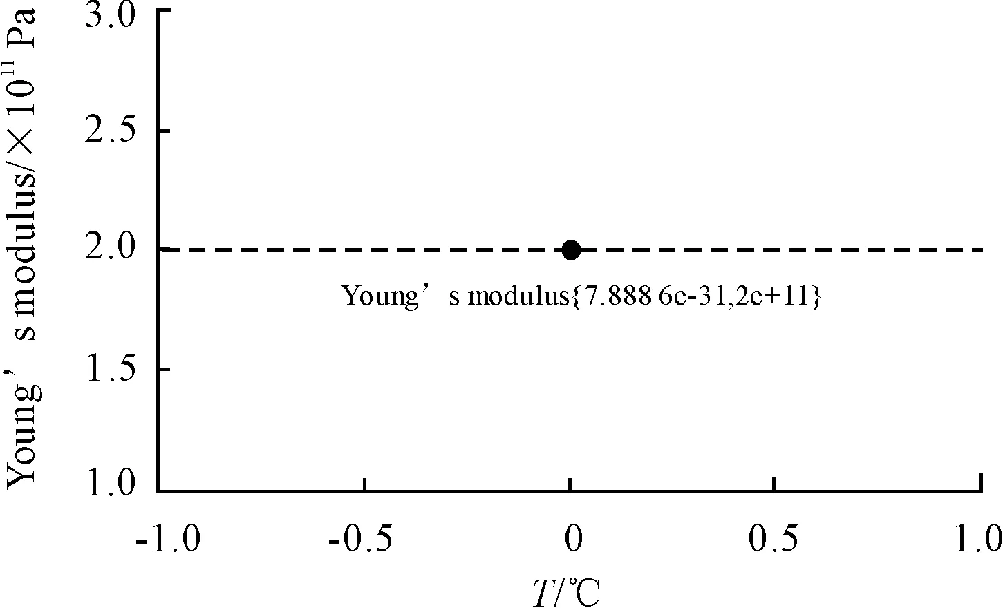
Fig.4 Young’s elastic modulus with temperature variation
3.2 The modal analysis
The material properties of the model are set up, in the meshing, mesh with the method is insert sizes, the size of the grid size is 0.005 m, a total of 515381 nodes, the cell number is 357554. To differentiate good model grid, as shown in Fig.5, we examined the grid quality which are good, and there was no big distortion phenomenon.
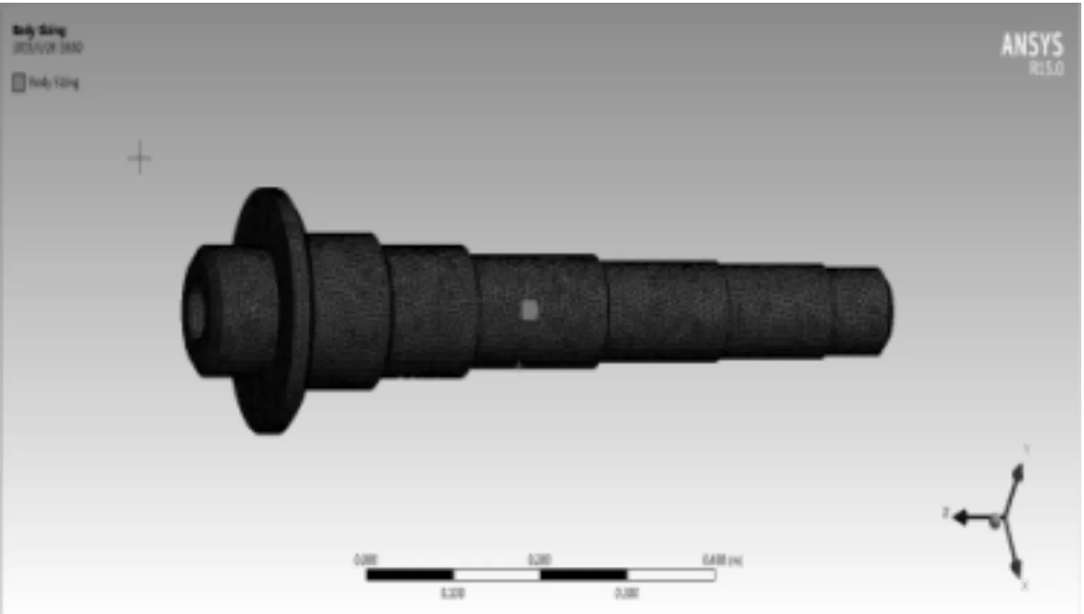
Fig.5 Meshing figure
For order selection, the study found that the vibration system with more than 1 000 degrees of freedom, to extract the first three order vibration mode, its precision can achieve 90% above, if extract of the first ten order modes, its accuracy can reach above 99% [8], so for the convenience of calculation, for some higher order modes can be neglected, mainly analyzes its low-order modes. In the process of calculation, extraction of the first six order vibration mode were analyzed, and modal analysis after the first six order natural frequency as shown in Table 3.
Table 3 Natural frequency of the first six order
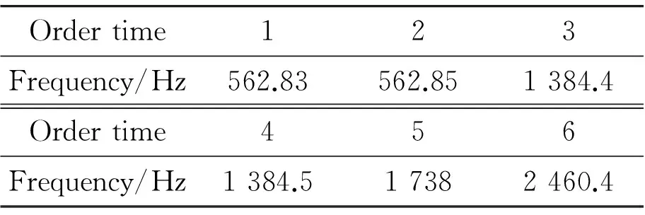
Ordertime123Frequency/Hz562.83562.851384.4Ordertime456Frequency/Hz1384.517382460.4
The first order frequency of main shaft is 562.83 Hz, and vibration mode is shown in Fig.6, as can be seen from its vibration mode: the torsional vibration of main shaft occurred along theXaxis, the biggest variable occurs in the central spindle. The second order frequency of main shaft is 562.85 Hz,and vibration mode is shown in Fig.7, as can be seen from its vibration mode: main shaft torsional vibration occurred along theYaxis, the biggest variable also occurs in the central spindle, and the main shaft of first and second order frequency is closed to. Third order frequency is 1 384.4 Hz, vibration mode is shown in Fig.8, as can be seen from its vibration mode: spindle happened along theXaxis bending vibration, the largest occurs in the central spindle shape variables on the right side. The forth order frequency is 1 384.5 Hz, and vibration mode is shown in Fig.9, as can be seen from its vibration mode: happened to the main shaft bending vibration along theYaxis, the biggest right form variables also occurs in the central spindle, and the main shaft of third-order and fourth-order frequency is closed to. The fifth order frequency is 1 738 Hz, vibration mode as shown in Fig.10, as can be seen from its vibration mode: spindle happened along theZaxis transverse compression vibration, maximize maximum shape variables in the main shaft diameter. The sixth order frequency is 2 460.4 Hz, and vibration mode is shown in Fig.11, as can be seen from its vibration mode: spindle happened along theXaxis bending vibration, the biggest variable occurs in the central spindle right. In the first six order modal, the maximum deformation is the sixth order.
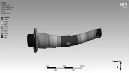
Fig.6 The first-order modal
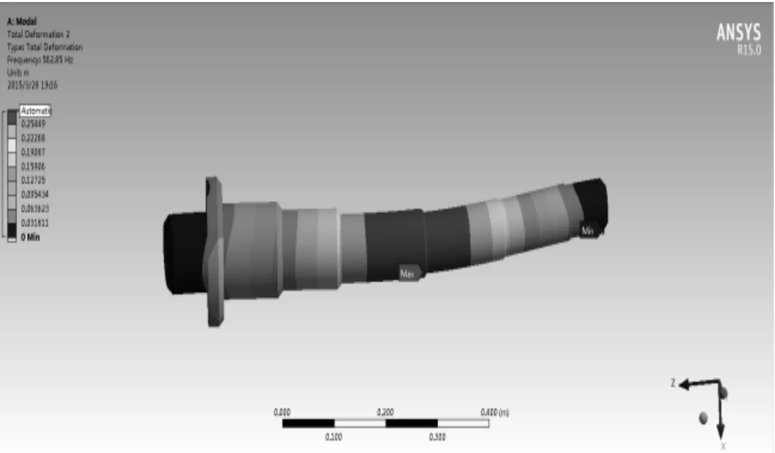
Fig.7 The second-order modal
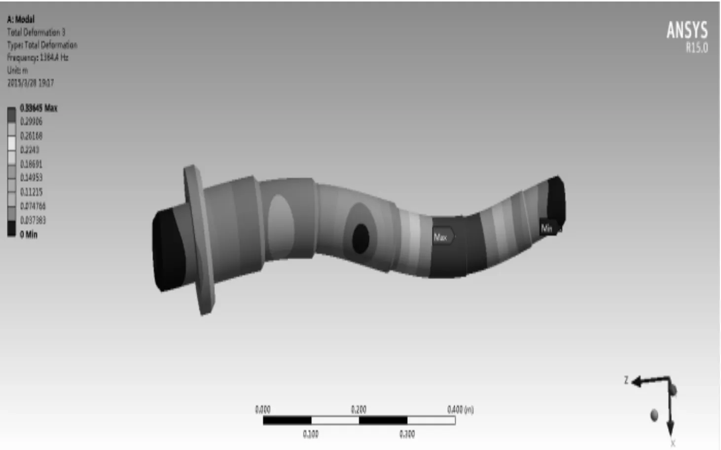
Fig.8 The third-order modal

Fig.9 The forth-order modal
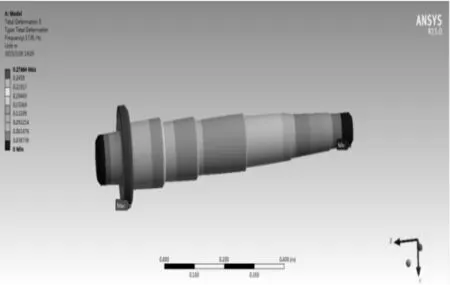
Fig.10 The fifth-order modal

Fig.11 The sixth-order modal
3.3 The harmonic response analysis
On the basis of the modal analysis and the harmonic response analysis was carried out on the spindle work condition by using ANSYS [9]. Because the spindle of the highest frequency is 2 460.4 Hz, here set the harmonic response frequency range is 0-1 640 Hz, harmonic response analysis need to impose a sine vibration force, here in the middle of the main force set 250 N, and the displacement response harmonic response curves analysis, as shown in Fig.12 and the normal stress response curve as shown in Fig.13, from curves we can see that harmonic response in the first order and second order is maximum, and deformation phase is 180 degrees, in the third and fourth order have the minimum deformation. So in the first and second order spindle are prone to resonance, and the low order natural frequency is higher than the natural frequency of the vibration of the spindle and the influence is large, the lower the frequency, the more violent vibration, the impact on the structure is large.
4 Experiments and analysis
4.1 Experiment systems
The modal experiment system is composed of 4 parts, which are the object, the excitation system, the data acquisition system and the data analysis system. In this experiment, the main shaft quality and the size are small, and the vibration device in the same number of magnitude, so the experimental use of non-stationary excitation system excitation device, which is exciting-hammer composed of hammer and sensor, and the input signal generated by excited vibration is pulse signal. Data acquisition system includes sensor, charge amplifier and signal acquisition system, in which the acceleration sensor will be collected signal by the charge amplifier, and the force on the force sensor to the signal collected together with the multi-channel data acquisition instrument for processing. Data acquisition instrument transfer data to a PC, using modal testing analysis software to estimate the frequency response function, to identify the measured object modal parameters and the modal change of structure. The modal test equipment of the spindle is shown in Table 4.

Fig.12 Displacement of the frequency response curve
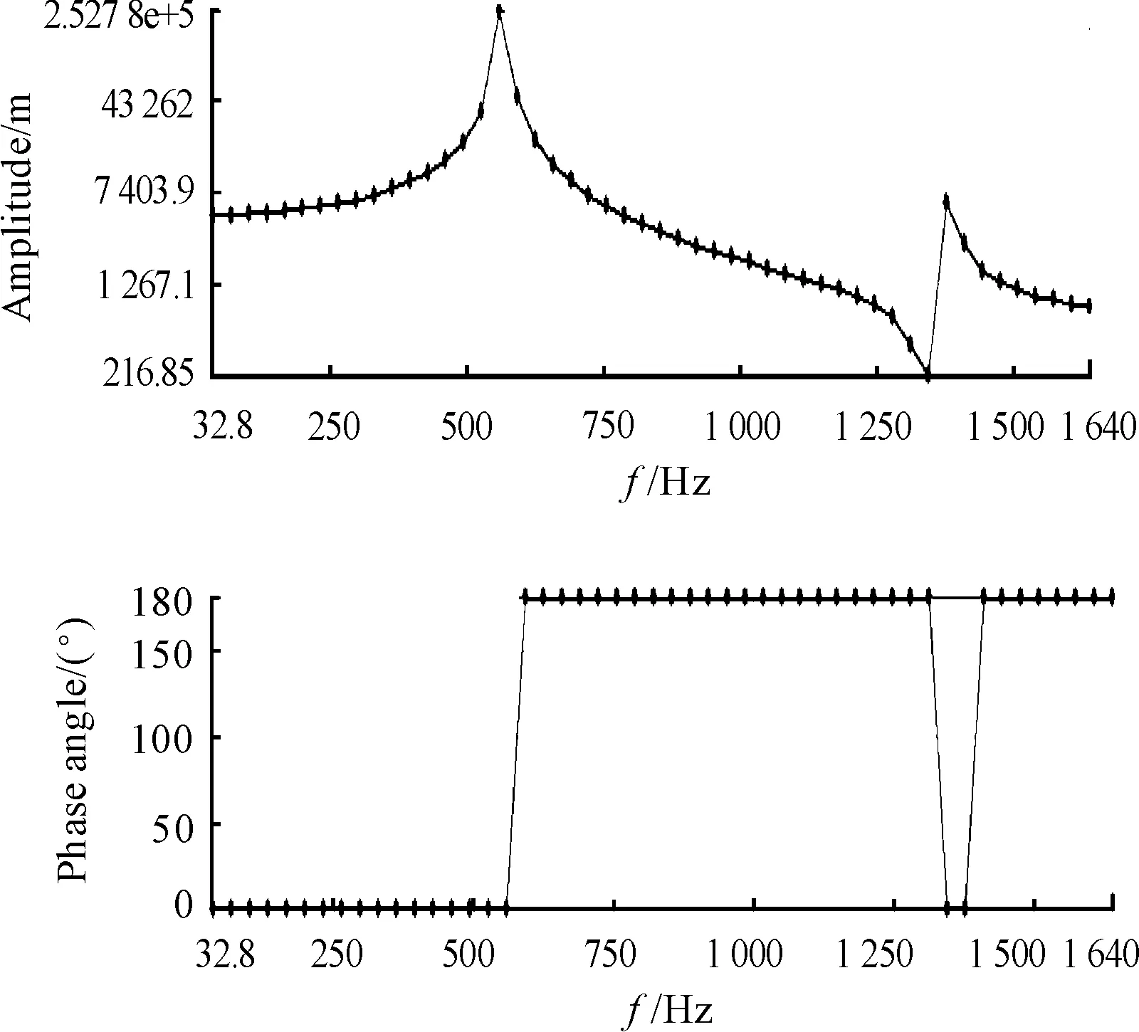
Fig.13 Under the action of normal stress response curve
Table 4 Modal test equipment of the spindle
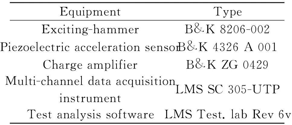
EquipmentTypeExciting-hammerB&K8206-002PiezoelectricaccelerationsensorB&K4326A001ChargeamplifierB&KZG0429Multi-channeldataacquisitioninstrumentLMSSC305-UTPTestanalysissoftwareLMSTest.labRev6v
4.2 Experiment analysis
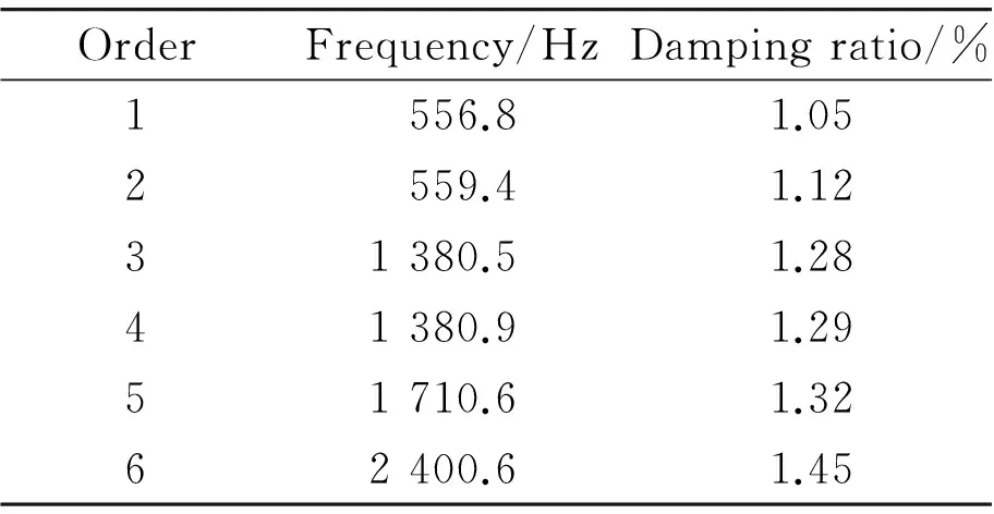
Modal experiment is the first to choose the correct object support, this experiment adopted free support and used with elastic rubber tube spindle hanging up, making the spindle in the free state approximation, with most of the degrees of freedom. In the process of the experiment, the hammer is used to knock on the main shaft, and a sensor is used for reference, and by moving the other sensors to measure the signal of each measurement point. In the experiment, the 3 measuring points are arranged in the vicinity of the front and back ends of the spindle and other 3 measuring points is arranged in the middle of the spindle, and a total of 9 measuring points are arranged in the total spindle. In the analysis of experimental results, the first response in two exciting point all the frequency response function of overall goodness of fit, which can show a spindle inherent resonance frequency more accurately, the modal of the spindle measured by experiment is shown in Table 5.
Table 5 Modal parameters of experiment
OrderFrequency/HzDampingratio/%1556.81.052559.41.1231380.51.2841380.91.2951710.61.3262400.61.45
Through the experiment that spindle modal as shown in Table 5, and Table 3 is calculated by the ANSYS finite element method, both error analysis as shown in Fig.14. Through the contrast analysis diagram can be seen the error is very small, and to verify the accuracy of the finite element method.
Because the vibration of the spindle changed with the motor variation speed, which belongs to the inherent characteristics, and has a smaller association with grinding state, therefore, the vibration experiment of the spindle with the variation rotating speed is also studied. In this paper, the measuring experiment is carried out with 360 r/min and 3000 r/min of two rotating speed, and the time domain signal of the maximum vibration displacement of the bearing area at both ends of the front and rear ends are shown in Fig.15 and Fig.16, and the frequency domain analysis of the bearing are shown in Fig.17, Fig.18.
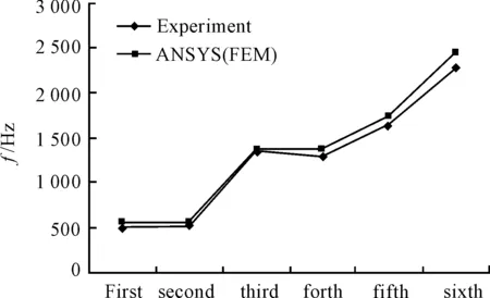
Fig.14 Error analysis chart

Fig.15 Time domain signal at 360 r/min

Fig.16 Time domain signal at 3 000 r/min
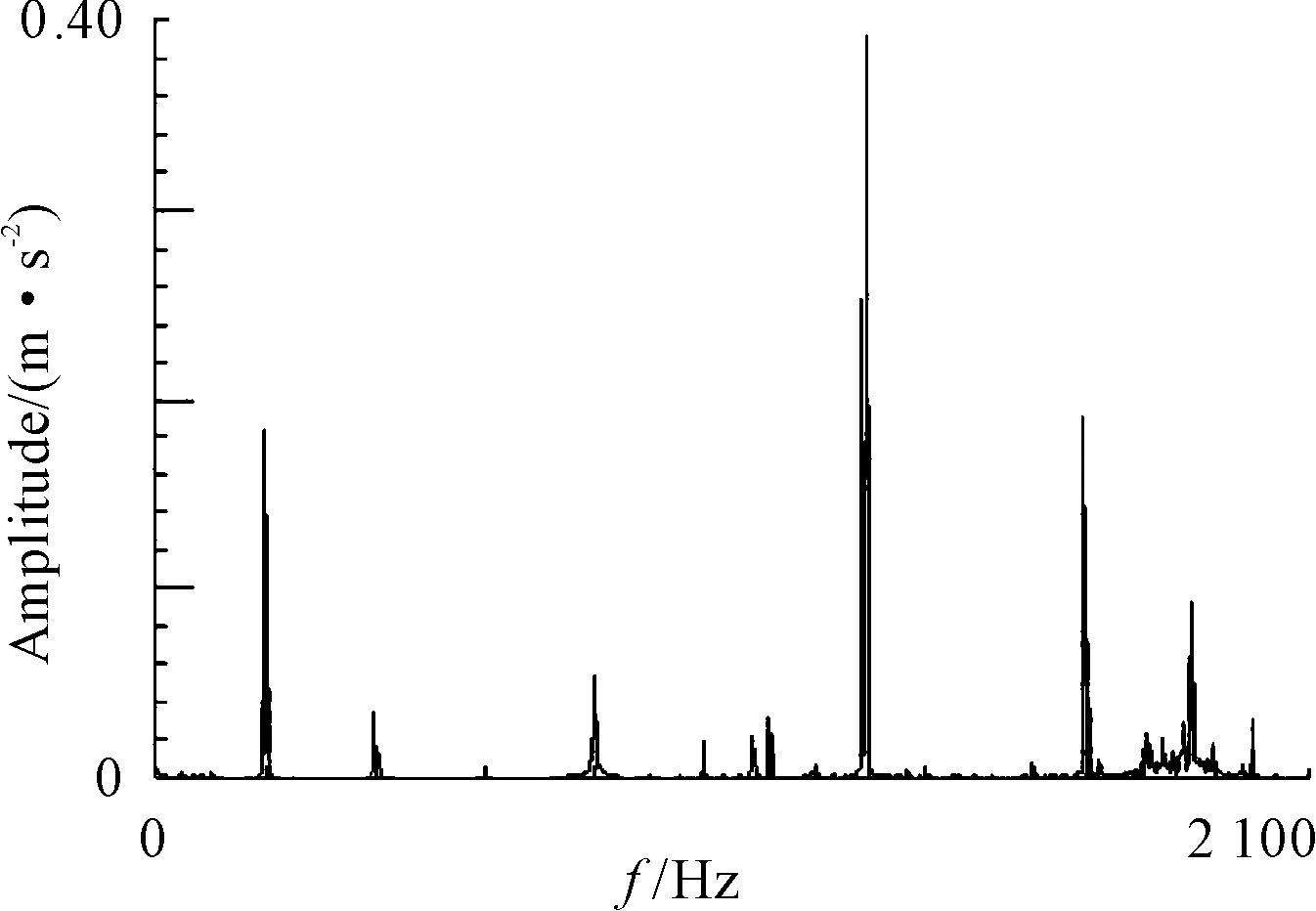
Fig.17 Frequency domain analysis at 360 r/min
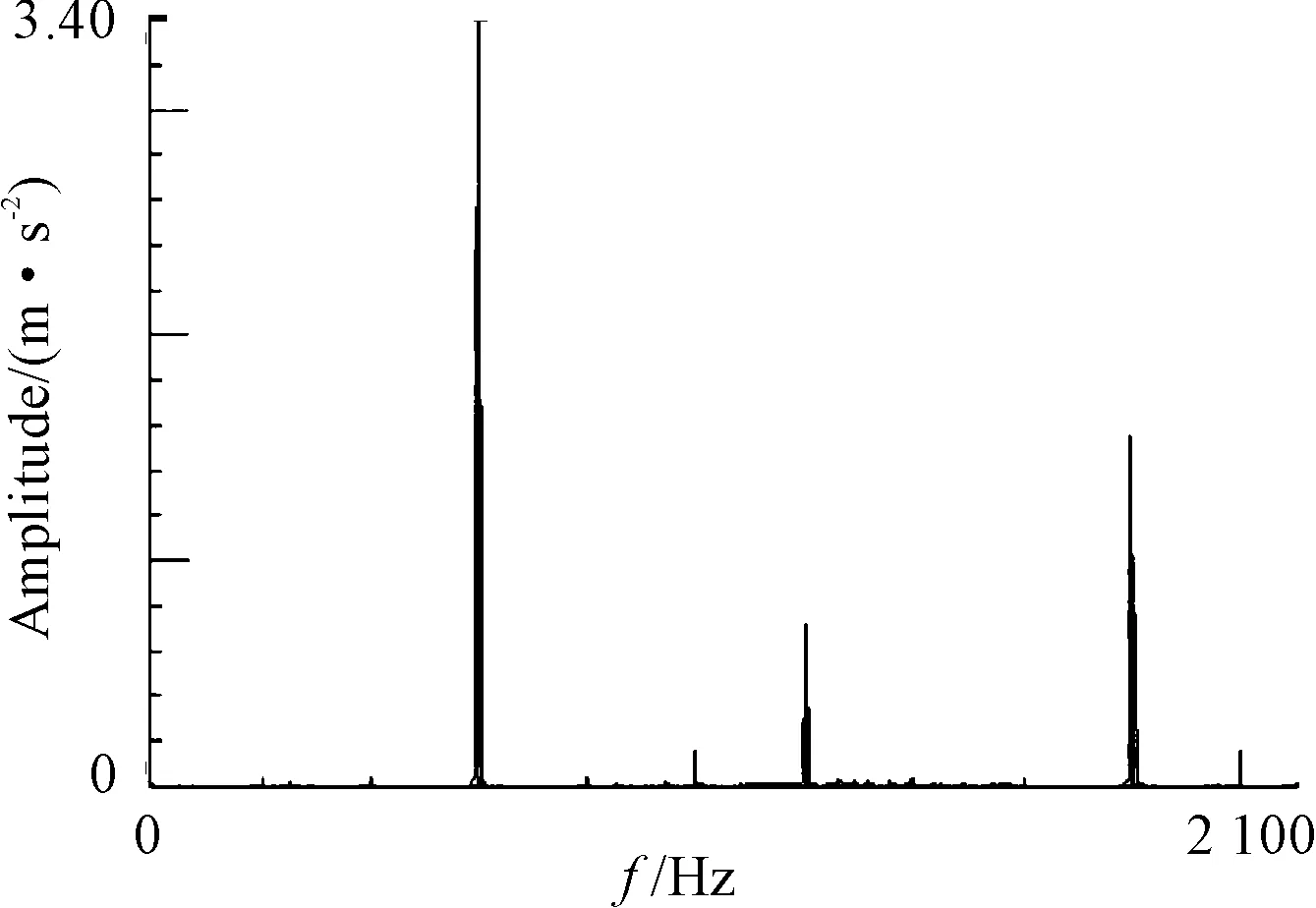
Fig.18 Frequency domain analysis at 3 000 r/min
As the accuracy and rigidity of the main shaft has not been unified the international standards, so the experimental reference to the German manufacturers of well-known manufacturers of GMN precision acceptance criteria as a reference. For the vibration of grinding spindle head with cutting tool and using ceramic ball bearing, the test standard of GMN company is less than 2 μm, but the main shaft used in this experiment did not install the tool, and the use of the ball bearing is still greater than 2 μm, from its spectrum also can be seen in the first and fifth order near the vibration. From the experimental data, the domestic production of precision spindle with foreign advanced level, there are still large compared to the gap, the main reason might be the spindle bearing, the manufacturing and assembly process and dynamic balance technology in three aspects.
5 Conclusions
This paper made an analysis for vibration modal and frequency response of the lathe spindle, by using finite element method based on ANSYS and the experiment respectively, through the research can get the following conclusion.
1) Through the modal analysis of the main shaft is obtained the 6 order natural frequency, the natural frequency of the first order and the second order is closed to, and the vibration is mainly torsional. The natural frequency of the third order and fourth order is also closed to, and the vibration is mainly bending.
2) Through the harmonic response analysis of the spindle can be obtained easily in one order and two order at the occurrence of resonance, and the low order natural frequency influence than the oscillation of high order natural frequencies of the spindle, the lower the frequency, the vibration is more intensive, which have large influence on the structure, So the work speed of the spindle system as far as possible to avoid first and second order critical speed, to improve reliability and service life of the spindle.
3) The experimental results show that the maximum vibration of the main shaft in the working state is mainly concentrated in the area near the ends of the bearing. So the improvement of bearing is an important way to reduce the vibration of the main spindle and ensure the machining accuracy.
Acknowledgement
This work is financially supported by Independent Innovation Research Fund of Wuhan University of Technology(No. 2014-ND-B1-09).
[1]FENG chengguo, CAO jujiang, ZHANG lei. Research on dynamic character of milling machining center worktable based on ANSYSWorkbench[J]. Hydromechatronics Engineering, 2013(4):175-177.
[2]YANG yongliang. The structural optimization of Lathe-Bed based on finite element [D]. Dalian: Dalian University of Technology, 2006.
[3]YANG hao, QIN ping, LI bolin, et al. Modle analysis of floor type boring and milling machine tool based on ANSYS[J]. Hydromechatronics Engineering, 2010(05):91-93.
[4]LI yaofang, LI duanneng, LIU zhi, et al. Modal analysis of cross platform on using hydrostatic guide-way hard turning machine tool[J]. Hydromechatronics Engineering, 2012(12): 21-24.
[5]YANG xiaowen. Modal Analysis of Vibration of Rolling Washing Machine[D].Shanghai: Shanghai Jiaotong University.
[6]Yang mingya, Yang yingjie. Dynamic performance analysis of high speed motorized spindle box[J]. Digital design, 2009(5): 68-70.
[7]Lv jianfa. Research on dynamic characteristics of NC boring and milling machine[D]. Chengdu: Xinan Jiaotong University, 2010.
[8]MAN jia, XU yanshen, ZHANG xueling. Modal analysis of vertical lathe beam based on ANSYS workbench[J]. Combination machine tools and automatic processing technology, 2006(6): 45-49.
[9]YAO Xiaobo, LIU deping, GAO Jianshe, et al. Dynamic analysis of machining center based on ANSYS Workbench[J]. Hydromechatronics Engineering, 2013(8):164-167.
(Continued on 69 page)
25 November 2014; revised 21 March 2015;
Ze-xin ZHOU, E-mail: 351268909@qq.com
10.3969/j.issn.1001-3881.2015.18.011 Document code: A
TB533+.1
accepted 2 July 2015
Hydromechatronics Engineering
http://jdy.qks.cqut.edu.cn
E-mail: jdygcyw@126.com

- 机床与液压的其它文章
- Design and simulation of the hardware in the loop simulation platform for vehicle ACC system
- A research on film thickness of a typical dynamic seal for hydraulic actuators
- The research on aero-engine gas path fault diagnosis by genetic algorithm-BP neural network
- The design of the hydraulic cylinder test bed based on cartridge valves
- Numerical simulation on the aerodynamic performance of ice coating airfoil of wind turbine blade
- Manufacturing of self-lubricating diamond tools with Ni-Cr alloy adding with Ni/C