
Wind Estimation for UAV Based on Multi-sensor Information Fusion
2015-11-21 07:08GaoYanhui高艳辉ZhuFeifei朱菲菲ZhangYong张勇HuShousong胡寿松
关键词:张勇
Gao Yanhui(高艳辉),Zhu Feifei(朱菲菲),Zhang Yong(张勇),Hu Shousong(胡寿松)
1.Research Institute of UAV,Nanjing University of Aeronautics and Astronautics,Nanjing 210016,P.R.China;
2.College of Automation Engineering,Nanjing University of Aeronautics and Astronautics,Nanjing 210016,P.R.China
Wind Estimation for UAV Based on Multi-sensor Information Fusion
Gao Yanhui(高艳辉)1*,Zhu Feifei(朱菲菲)2,Zhang Yong(张勇)1,Hu Shousong(胡寿松)2
1.Research Institute of UAV,Nanjing University of Aeronautics and Astronautics,Nanjing 210016,P.R.China;
2.College of Automation Engineering,Nanjing University of Aeronautics and Astronautics,Nanjing 210016,P.R.China
Aiming at the requirements of accurate target positioning and autonomous capability for adapting to the environmental changes of unmanned aerial vehicle(UAV),a new method for wind estimation and airspeed calibration is proposed.The method is implemented to obtain both wind speed and wind direction based on the information from a GPS receiver,an air data computer and a magnetic compass,combining with the velocity vector triangle relationships among ground speed,wind speed and air speed.Considering the installation error of Pitot tube,cubature Kalman filter(CKE)is applied to determine proportionality calibration coefficient of true airspeed,thus improving the accuracy of wind field information further.The entire autonomous flight simulation is performed in a constant 2-D wind using a digital simulation platform for UAV.Simulation results show that the wind speed and wind direction can be accurately estimated both in straight line and in turning segment during the path tracking by using the proposed method.The measurement accuracies of the wind speed and wind direction are 0.62 m/s and 2.57°,respectively.
wind estimation;airspeed calibration;unmanned aerial vehicle(UAV);cubature Kalman filter(CKE)
0 Introduction
Small and micro aerial vehicles are increasingly used to improve situational awareness by conducting surveillance,patrolling and convoy protection.Due to the inescapable fact that the low airspeed of unmanned aerial vehicles(UAVs)is comparable to the prevailing wind speed,constant wind and turbulence have a large impact on aircraft flight performance,energy consumption and aviation safety,specially for small and micro UAVs.Wise usage of wind information during navigation,such as thermal soaring and formation flight,can significantly increase the flight endurance of small UAVs.Sohn et al.[1]pointed out that such wind information could provide more accurate geo-location of a ground target. Additionally,the obtained crab-angle could help improve the control performance of a UAV in path following,landing tasks,etc.In fact,the wind estimation has become an important application of meteorological UAV[2].
Generally,the wind estimation for UAV can be roughly divided into three categories.The most widely used approach is graphical method based on the vector relationship among ground speed Vg,air speed Vaand wind speed Vw[3]as shown in Eig.1,where ground speed is measured by radar or GPS,and air speed by a pitot tube and air data computer.Ref.[3]employed this method to calculate wind speed directly,circulating flight repeatedly to perform measurement calibration gradually by fixed airspeed of UAV.The second category is the constant wind estimation method using nonlinear Kalman filtering[4-5],which adopts a nonlinear Kalman filter to conduct wind field estimation based on a constant windmodel without the reflection of abrupt change of wind velocity like wind gust.The third is the time-varying wind estimation method of non-Kalman filtering[6].Wind speed is estimated according to measurement corrections,nonlinear kinetic equation,nonlinear wind model,and time delayed moving average filter.But the method is limited to the numerous flight parameters,aerodynamic model and the case of a low speed aircraft such as a small UAV.
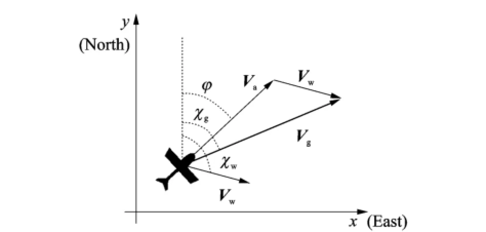
Eig.1 Wind triangle
This paper proposes a new method for estimating wind speed and direction,using the measurement information outputting from a GPS receiver,the air data computer and magnetic compass.The proposed method also calibrates the airspeed scale factor that simplifies its application to low-cost UAVs.The method differs from previously used techniques in that it does not require a specific UAV flight maneuvers and can accurately estimate in straight line and turning segment during the trajectory following.
The implementation of wind estimation and airspeed calibration algorithm is first elaborated here.Subsequently the digital simulation platform for UAV is introduced briefly,along with the simulation results of wind estimation algorithm.Einally several conclusions are drawn.
1 Algorithm for Wind Estimation and Its Implementation
1.1 Algorithm for wind estimation
UAV flight kinematics satisfies the velocity vector triangle in the wind field,as shown in Eig.1.Namely

The Earth-fixed reference frame(EE)is selected for calculation.GPS receivers output the information of the ground speed Vg,vertical velocity Vdand course angleχgin the EE.This paper mainly considers the 2-D constant wind model,which includes two parameters of wind speed and wind direction similarly using EE.The air data computer outputs airspeed in the flight-path reference frame(EW),therefore,the transformation from flight-path to body axes is required. Small UAV generally uses coordination turning flight,and the rudder is mainly used to eliminate sideslip angle,thus assumingβ≈0.When the UAV is in a flight at a stable level,the formula α≈θholds,thus
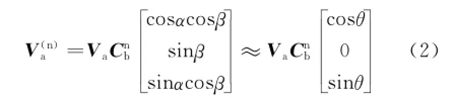
where the superscripts″n″and″b″denote the Earth-fixed and the body-fixed reference frames,respectively.Cnbis the transformation matrix from the body-fixed reference frame to the Earth-fixed reference frame[7],namely

Inserting the GPS information,wind condition,as well as Eqs.(2—3)into Eq.(1),an vector relationship can be yielded.
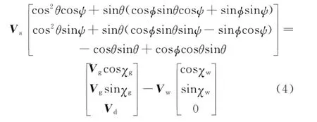
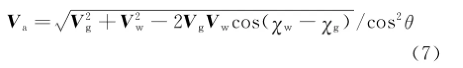
Generally speaking,the attack angle is small,for the sake of simplicity,assuming that sinθ≈0.In the 2-D horizontal plane,two equations can be obtained.
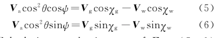
Calculating quadratic sum of Eqs.(5—6)yields
Airspeed V outputed from air data computer is calculated using the dynamic pressure and static pressure measured by a Pitot tube according to the Bernoulli′s equation[4].
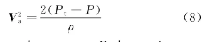
where Ptis the total pressure,P the static pressure,andρthe air density.
The pressure measured by the head of airspeed tube and static pressure orifice is not exactly the same with the true value.Assuming that the attack angle of a pitot tube is small,the total pressure error measured by a pitot tube will be miniature.However,the static pressure error will be large.This is because the airflow near the static pressure orifice is disturbed due to the pressure sensor itself and the aircraft structure. Meanwhile,for the low-cost UAVs,the mounting position and orientation of a pitot tube may differ for each flight test leading to installation error changing greatly.
Eor the angle of attack if sideslip angle exists,the relationship between UAV airspeed and Vpitotcan be expressed as follows

Therefore,the compensation factor sf is established aiming at the actual atmospheric environment,installation errors,attack and sideslip angle.
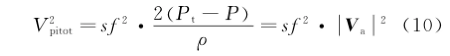
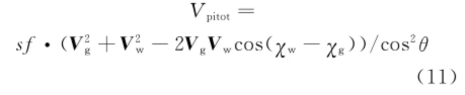
Substituting Eq.(7)into Eq.(9)gains
Dividing Eq.(6)by Eq.(5),we have

The heading angle is measured by magnetic compass.The measurement of magnetic compass is the magnetic azimuth where the magnetic north direction uses the UAV longitudinal axis as a reference.The magnetic azimuth should be modified by a correction value(magnetic declination)in order to obtain the true azimuth of UAV longitudinal axis using the north direction as a reference. Assuming that magnetic declination in UAV flight area changes slightly,as long as conducting magnetic declination correction before the flight according to the take-off direction,the influences of magnetic declination angle on the precision of wind speed measurement can be ignored.
1.2 CKF algorithm
Recently proposed cubature Kalman filter(CKE)is a Gaussian approximation to Bayesian filter that could be used to solve a wide range of nonlinear filtering problems.The heart of the CKE is the third-degree spherical-radial cubature rule which makes it possible to compute the integrals encountered in nonlinear filtering problems. According to the spherical-radial cubature criterion,CKE calculates points with the same weight and diffuses them directly using nonlinear equations to conduct state estimation.With no need for linearization of nonlinear model,the estimation accuracy can reach three order.CKE performs better in nonlinear function approximation,numerical accuracy,and stability of the filter.In addition,the implementation is simple too[8-9].
Considering the multidimensional weighted integration as Eq.(14),the integral analytical value generally cannot be obtained,therefore it is necessary to select a group pointswith the weight to approximate the integral as Eq.(15).

A CKE uses third-degree spherical-radial rule to generate the cubature-point setwith the same weight when the dimension of the random variable is n.
After calculating cubature point set{ξi,ωi},the CKE algorithm can be obtained based on time update and measurement update.
The time update step[10]
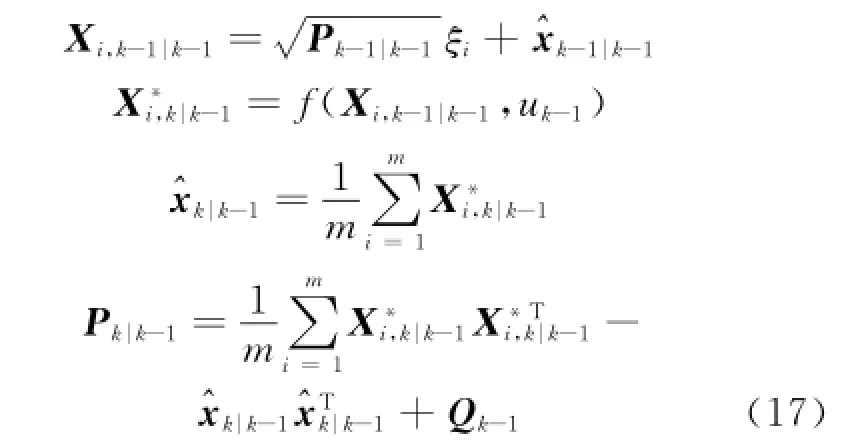
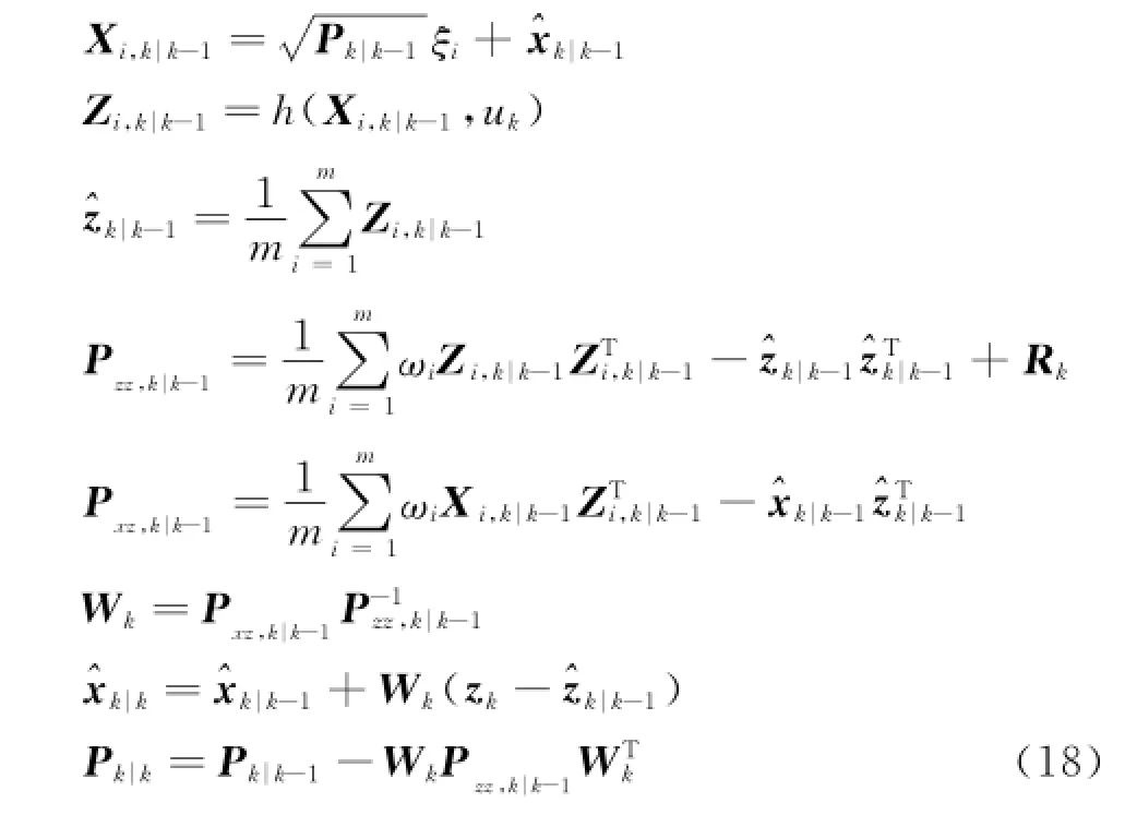
The measurement update step
1.3 Wind estimation algorithm implementation
With the assumption of a constant 2-D wind,a CKE method is suggested to estimate the wind speed,wind direction and airspeed calibration coefficient simultaneously.These variables can be regarded as constant approximately during some flight time.The states are modeled as a randomwalk process[4].

where F is the unit matrix and w~N(0,Q)k.
The ground velocity and the course angle,both of which are outputs of the GPS receiver,and the pitch angle measured from vertical gyroscope are accurate enough to be treated as known parameters in each epoch.With the measured variables zk=[Vaψ],the nonlinear observation equation is expressed as
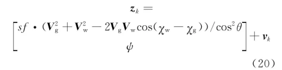
where vk~N(0,Rk),andψis described by Eq.(13).
In the simulations,the measurement and the process noise covariance are tuned using real flight test results.The initial guess at the wind vector is obtained by calculating the velocity vector triangle.
2 Simulation and Verification
2.1 Simulation platform
This section is devoted to the simulation analysis for characterizing the performance of the CKE developed in Section 1.The filter has been tested with the simulated flight data provided by a certain UAV digital simulation platform[11-12]. The controller of a certain UAV employs the method of classical proportional differential(PD)control,which comprises of an inner loop and an outer loop.The autonomous navigation algorithm uses lateral offset and the rate of lateral offset directly to calculate given roll angle for autonomous flight guidance.
2.2 Simulation results

The UAV conducted the entire autonomous flight simulation on a digital simulation platform. The vehicle was flying over a preplanned sequence of waypoints.The constant wind disturbance was created at the level flight.The angle between the directions of direct crosswind and airline in level flight segment was 90°.This was almost the worst case with respect to the initial value guesses.The CKE filter started to work after UAV achieved a steady flight.The estimation results of wind speed,wind azimuth,and scaling factor of airspeed calibration were shown in Eig.2.The associated estimation errors were shown in Eig.3.

Eig.2 Simulation results of wind speed,wind direction and calibration coefficient
Erom Eigs.2,3,the CKE estimation switched automatically in 300 s.The whole flight process can be divided into four phases:the phase of straight line(300—670 s),the phase of a half of round turn(670—900 s),the phase of straight line(900—1 130 s),and the phase of a round turn(1 130—1 400 s).In the UAV straight line autonomous flight process,the wind speed and calibration coefficient can be predicted rapidly. Erom Eig.2(a)and Eig.3(a),the wind speed residual is less than 0.5 m/s during the whole estimation process.Erom Eig.2(b)and Eig.3(b),the wind direction residual is less than 3°after a semicycle flight,and the wind direction residual is less than 1°after a round flight.Eurthermore,from Eig.2(c)and Eig.3(c),the calibration coefficient residual is less than 0.006.The estimation results of the wind speed,wind direction and calibration coefficient all satisfy the residual requirements of 3δbound.And it shows that the CKE estimation results are credible.
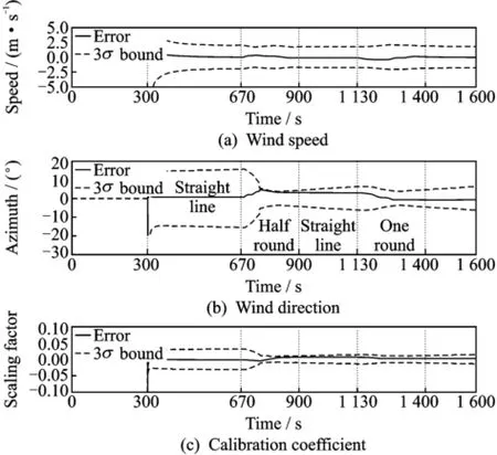
Eig.3 Simulation results of residuals with 3σbounds
As an objective measure of the CKE estimation method is preferable,the average of the root mean squared error(δ)is calculated for different flight segment
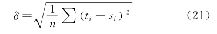
where t is the truth-value and s the value of simulation.
The results of the performed estimations in different flight segments are summarized in Table 1,where the unreported accuracies are left blank. Also,the CKE wind component observations are compared with accuracies of conventional atmospheric profiling systems such as atmospheric wind profiler,radiosondes and meteorological UAV.
In Table 1,the measuring precision of wind field information estimated by CKE method is superior to the traditional wind measurement equipments.The convergence time of filtering is the flight time of semicycle,and the measurement accuracies of wind speed and wind direction are 0.62 m/s and 2.57°,respectively.
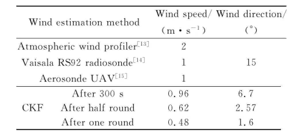
Table 1 Comparison of accuracies for wind component observations
3 Conclusions
A new method is presented for estimating wind speed and direction as well as for calibrating the airspeed using GPS receiver,air data computer,magnetic compass and vertical gyroscope. The proposed algorithm uses the geometrical relation of ground,wind speed and airspeed,which does not depend on aerodynamic model.The simulation results show that the recommended CKE estimation method can obtain reasonable wind speed,wind direction information only within a round of UAV autonomous turn flight.The estimated scaling factor also corrects the airspeed to a reasonable level.The wind speed and wind direction of UAV in current airspace can be acquired by the proposed method in real-time,which contributes to the more accurately location and time predication of task-performing for commanders. Therefore,the method is conducive to complete operational mission synergistically.Simultaneously,the method provides research foundation for the subsequent UAV real-time path planning in wind fields.
Acknowledgement
This work was supported by the Pre-research Eoundation of Chinese People′s Liberation Army General Equipment Department(No.51325010601).
[1] Sohn S,Lee B,Kim J,et al.Vision-based real-time target localization for single-antenna GPS-guided UAV[J].IEEE Transactions on Aerospace and Electronic Systems,2008,44(4):1391-1401.
[2] Buschmann M,Bange J,Vörsmann P.MMAV-A miniature unmanned aerial vehicle(MINI-UAV)for meteorological purposes[C]∥16th Symposium on Boundary Layers and Turbulence.Portland,United states:American Meteorological Society,2004:263-269.
[3] Hollister W M,Bradford E R,Welch J D.Using aircraft radar tracks to estimate winds aloft[J].MIT Lincoln Laboratory Journal,1989(2):555-565.
[4] Cho A,Kim J,Lee S,et al.Wind estimation and airspeed calibration using a UAV with a single-antenna GPS receiver and pitot tube[J].IEEE Transactions on Aerospace and Electronic Systems,2011,47(1):109-117.
[5] Pachter M,Ceccarelli N,Chandler P.Estimating MAV′s heading and the wind speed and direction using GPS,inertial,and air speed measurements[C]∥AIAA Guidance,Navigation and Control Conference and Exhibit.Honolulu,USA:AIAA,2008:1-25.
[6] Langelaan J W,Alley N,Neidhoefer J.Wind field estimation for small unmanned aerial vehicles[J]. Journal of Guidance,Control,and Dynamics,2011,34(4):1016-1030.
[7] Phillips W E.Mechanics of flight[M].2nd Ed. Hoboken,USA:John Wiley&Sons,Inc,2010.
[8] Gu Dongqing,Qin Yongyuan,Peng Rong,et al. Rapid transfer alignment using federated Kalman filter[J].Transactions of Nanjing University of Aeronautics and Astronautics,2005,22(2):139-143.
[9] Liu Lin,Li Hui,Dai Beiqian,et al.Speech enhancement method based on Kalman filtering and multipluse excitation[J].Journal of Data Acquisition and Processing,2009,24(1):100-104.
[10]Arasaratnam I,Haykin S.Cubature Kalman filters[J].Automatic Control,IEEE Transactions on,2009,54(6):1254-1269.
[11]Gao Yanhui,Xiao Qiangui,Hu Shousong,et al. Elight control system simulation platform for UAV based on integrating simulink with stateflow[J]. Telkomnika-Indonesian Journal of Electrical Engineering,2012,10(5):985-991.
[12]Liu Rong,Lu Yuping,Xiao Qiangui.Low-cost and super-applicability digital navigation and control system of super-size UAV[J].Journal of Nanjing University of Aeronautics&Astronautics,2009,41(S):19-23.
[13]Sun Xuying,Han Hui,Duan Haixia,et al.Comparative analysis on wind data from atmospheric wind profiler and balloon sounding[J].Arid Meteorology,2008,26(3):48-52.
[14]Li Wei,Xing Yi,Ma Shuqing.The analysis and comparison between GTSl radiosonde made in China and RS92 radiosonde of Vaisala Company[J].Meteorological Monthly,2009,32(10):97-102.
[15]Soddell J R,McGuffie K,Holland G J.Intercomparison of atmospheric soundings from the aerosonde and radiosonde[J].Journal of Applied Meteorology,2004,43(9):1260-1269.
(Executive editor:Zhang Tong)
O321 Document code:A Article ID:1005-1120(2015)01-0042-06
(Received 15 November 2014;revised 5 January 2015;accepted 12 January 2015)
*Corresponding author:Gao Yanhui,Associate Researcher,E-mail:gyh2005@nuaa.edu.cn.
How to cite this article:Gao Yanhui,Zhu Eeifei,Zhang Yong,et al.Wind estimation for UAV based on multi-sensor information fusion[J].Trans.Nanjing U.Aero.Astro.,2015,32(1):42-47.
http://dx.doi.org/10.16356/j.1005-1120.2015.01.042
猜你喜欢
Chinese Physics B(2022年11期)2022-11-21
Chinese Physics B(2022年7期)2022-08-01
Chinese Physics B(2022年7期)2022-08-01
做人与处世(2022年6期)2022-05-26
做人与处世(2022年4期)2022-05-26
科技风(2022年7期)2022-03-15
书香两岸(2020年3期)2020-06-29
小猕猴学习画刊·下半月(2019年8期)2019-09-16
故事会(2018年24期)2018-01-02
理科考试研究·初中(2017年4期)2017-11-04
 Transactions of Nanjing University of Aeronautics and Astronautics2015年1期
- Transactions of Nanjing University of Aeronautics and Astronautics的其它文章
- CRB for 2-D DOA Estimation in MIMO Radar with UCA
- Flight Dynamic Analysis of Hypersonic Vehicle Considering Liquid-Solid Coupling
- Tradeoff Analysis of Factors Affecting Longitudinal Carrier Landing Performance for Small UAV Based on Backstepping Controller
- Improved Shuffled Frog Leaping Algorithm Optimizing Integral Separated PID Control for Unmanned Hypersonic Vehicle
- Beamforming of Whole Airspace Phased Array TT&C System Based on Linear Subarrays
- Trim Drag Prediction for Blended-Wing-Body UAV Configuration