
Numerical Study on the Hydrodynamic Behaviors of a Ship Passing Through a Lock in Shallow Water
2015-12-12 08:52WANGHongzhiZOUZojin
船舶力学 2015年6期
WANG Hong-zhi,ZOU Zo-jin,b
(a.School of Naval Architecture,Ocean and Civil Engineering;b.State Key Laboratory of Ocean Engineering,Shanghai Jiao Tong University,Shanghai 200240,China)
0 Introduction
There are many kinds of restricted waters such as harbors,bays,canals,locks or inland waterways.In these restricted waters,the maneuvering performance of a ship is affected by shallow water effect or bank effect.Especially in locks,these effects are significant because of the restricted size of lock chamber.Many numerical studies on ship hydrodynamic behavior in restricted waters have been completed.Choi and Mei[1]and Chen and Sharma[2]solved the Kadomtsev-Petviashvili(KP)equation to investigate the upstream solitons in shallow water channels.Gu and Wu[3]used Computational Fluid Dynamics(CFD)to calculate the resistance of a ship moving near the critical speed in shallow water.Huang[4]calculated the viscous flow about a swirling ship in shallow water.But the hydrodynamic performance of ships moving in locks is quite complicated and not yet fully understood.Therefore,to gain a clear insight into the hydrodynamic performance of a ship passing through a lock,it is necessary to carry out study on this special case.
During the last twenty years,model test methods were used to investigate the hydrodynamic performance of a ship passing through a lock at Flanders Hydraulics Research and Ghent University,Belgium.Verwiligen and Richter[5]analyzed the entering maneuver of full form ships into the Terneuzen West Lock by means of model tests,full scale trials and realtime simulations.Delefortrie et al[6-7]assessed the navigation behavior of three different ship models in the third set of Panama locks and analyzed the influence of approach wall configurations,eccentricities,propeller rates,approach scenarios and under keel clearances.In the 1990s,a systematic captive model test was carried out in the Towing Tank for Manoeuvres in Shallow Water(Co-operation Flanders Hydraulics Research and Ghent University)[8]in Antwerp to study the feasibility for receiving bulk carriers with larger beam in the Pierre Vandamme Lock in Zeebrugge[9].
Besides model test methods,numerical methods are used to investigate navigation locks.Thorenz[10-11]gave an excellent overview of the state-of-the-art of CFD in lock design and used CFD to evaluate the filling and emptying systems for the new Panama Canal locks.De Mulder[12]gave an overview about the main features,progress and challenges of CFD modelling for lock design purpose.In the present paper,the CFD software FLUENT is used to simulate the unsteady viscous flow around a ship entering the Pierre Vandamme Lock.The numerical results are compared with experimental data to verify the numerical methods.The numerical computation is implemented at different ship speed,eccentricity and water depth to investigate the effects of these factors on the hydrodynamic behaviors of a ship passing through a lock in shallow water.
1 Problem formulation
As shown in Fig.1,a space-fixed right-handed coordinate system o-xyz is used for describing ship kinematics and dynamics.The longitudinal Ox-axis is pointing to the moving direction of the ship,the lateral Oy-axis is directed towards starboard.

Fig.1 Coordinate system
Under the assumption of low ship speed,the elevation of free surface is neglected.The unsteady viscous flow field is governed by the Navier-Stokes equations.Using Reynolds-Averaged method,the governing equations for this flow problem are:


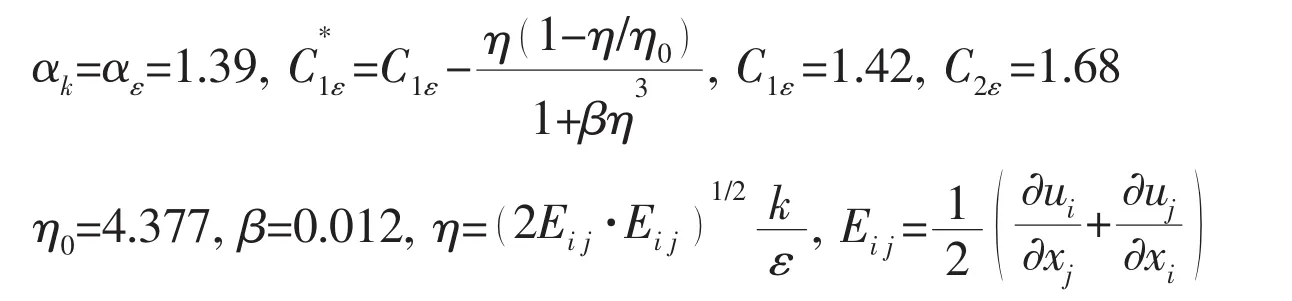
Turbulence model has to be used to closure the governing equations.In this paper,the RNG k-ε turbulence model is adopted.The transportation equations of turbulence kinetic energy k and its rate of dissipation ε are:

where μeff=μ+μt,μtis the turbulence viscosity;Gkrepresents the generation of turbulence kinetic energy due to the mean velocity gradients.They are expressed as:

The other terms have the following values and expressions:
2 Numerical computation
2.1 Ship and lock model
To compare with the available model test data,a bulk carrier ship passing through the Pierre Vandamme Lock is chosen for the numerical study.The model scale ratio is 1/75.The main dimensions of the ship and the model are listed in Tab.1.The Pierre Vandamme Lock has a length of 500 m,a width of 57 m and a depth of 18.5 m.Fig.2 shows the lock configuration in towing tank for model tests,where the dashed line stands for the center line of lock chamber.

Tab.1 Ship characteristics:bulk carrier

Fig.2 Lock configuration in towing tank for captive model tests
2.2 Computational domain and boundary conditions
It is assumed that the ship speed is so small that the wave-making effect can be neglected;therefore,the free surface can be replaced by a horizontal plane and is modeled by means of a frictionless rigid lid.Fig.3 shows the computational domain.On the ship hull,the water bottom,the lock gate,the channel bank and lock chamber bank,a no-slip wall boundary condition is set.On the outflow boundary,a pressure outlet boundary condition is imposed.

Fig.3 Computational domain
2.3 Dynamic mesh method and grid generation
In this paper,the layering method is used to simulate the relative motion between the ship and the lock.When using the layering method,boundary conditions on the interfaces between moving zone and stationary zone are set as interface.It uses interpolation method to calculate the flux cross two interfaces.As shown in Fig.4,the zone containing the ship is set as moving zone which moves with the ship speed,and the dashed line indicates the interface.Boundaries indicated by solid ellipse and dashed ellipse are places where grids split and collapse.

Fig.4 Definition of moving zone
As shown in Fig.5,a combination of mixed tetrahedral mesh and hexahedral mesh grid is adopted.The hexahedral grid is used in mid-ship part and adaptable tetrahedral grid is used in bow and stern parts where geometric hull is complex.In the rest of fluid field,the hexahedral grid is used.
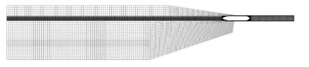

Fig.5 Sketch of grid distribution
2.4 Solution settings
UDF(User-defined function)is a function programmed by the user that can be dynamically linked with the FLUENT solver to enhance the standard features of the code.In this paper,UDF is used to set the speed of ship,to define the gravity center of the ship and to calculate the force and moment acting on the ship.UDF is also used to output the results as text file to edit.
The unsteady part in governing equations is discretized by the first-order implicit scheme.The algorithm SIMPLE is chosen to solve the velocity-pressure coupling problem.Momentum,turbulent kinetic energy,turbulent dissipation rate are discretized by second-order upwind scheme.Wall function is used to reduce computational burden for near-wall flow simulation.Time step is set as 0.1s to make sure that the product of the time step times velocity is smaller than the mesh size in moving zone.
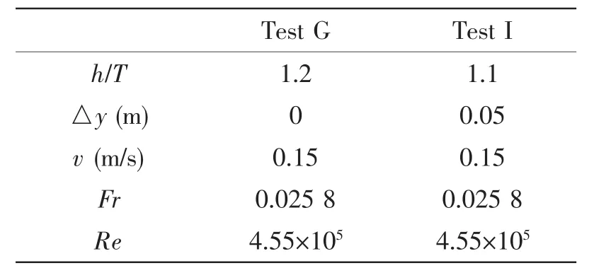
Tab.2 Overview of tests G and I
Test G and Test I in the model tests are selected for numerical simulation.The main parameters of two model tests are listed in Tab.2,where△y is the eccentricity.
The hydrodynamic force and moment acting on the hull are obtained by the numerical method.The mean sinkage σ,trim τ and heel angle φ are determined from the calculated sinking force Z,trim moment M and heel moment K by the following formulae:
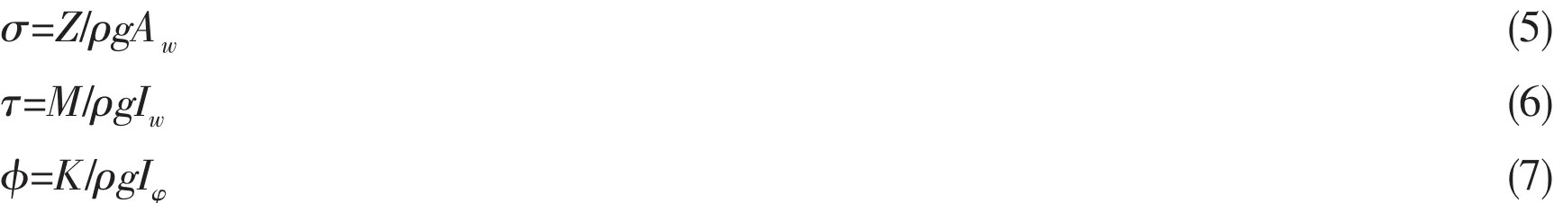
where Awrepresents the waterplane area,Iwand Iφdenote the longitudinal and lateral moment of inertia of the waterplane area about the centre of floatation.
The vertical displacements of the fore and aft perpendiculars zFP and zAP can be obtained by

3 Numerical results and discussion

3.1 Grid sensitivity study
In order to study the grid sensitivity,three systematically varied grids are generated with a uniform grid refinement ratiowhere hi+1and hiare the grid spacing of two successively refined grids.Tab.3 gives the dimensions of the three grids,taking the simulation of test G as an example.The results of grid sensitivity study are shown in Fig.6.As it can be seen,the difference of the calculated results between Grid 2 and Grid 3 is very little.The Grid 2 is finally adopted in the simulation.

Tab.3 Mesh number of grid series in the simulation of test G

Fig.6 Effect of the mesh number of grids in the simulation of test G
3.2 Comparison between numerical and test results
Figs.7 and 8 show the time histories of the calculated hydrodynamic forces and corresponding vertical displacements of the fore and aft perpendiculars compared with the results of model test.All results are plotted as a function of the longitudinal position of the model’s mid-ship section.The maximum value of results of test I is larger than that of test G.We could deduce that the water depth and eccentricity have a major effect on the hydrodynamic forces.In general,the present prediction results of hydrodynamic lateral force and yaw moment are in good agreement with the experimental data,while the longitudinal force is underestimated because of increasing blockage in navigation lock under test conditions.Because the shape of the lock is asymmetrical,the values of lateral force and yaw moment are remarkable.

Fig.7 Calculated results compared with experimental data of test G
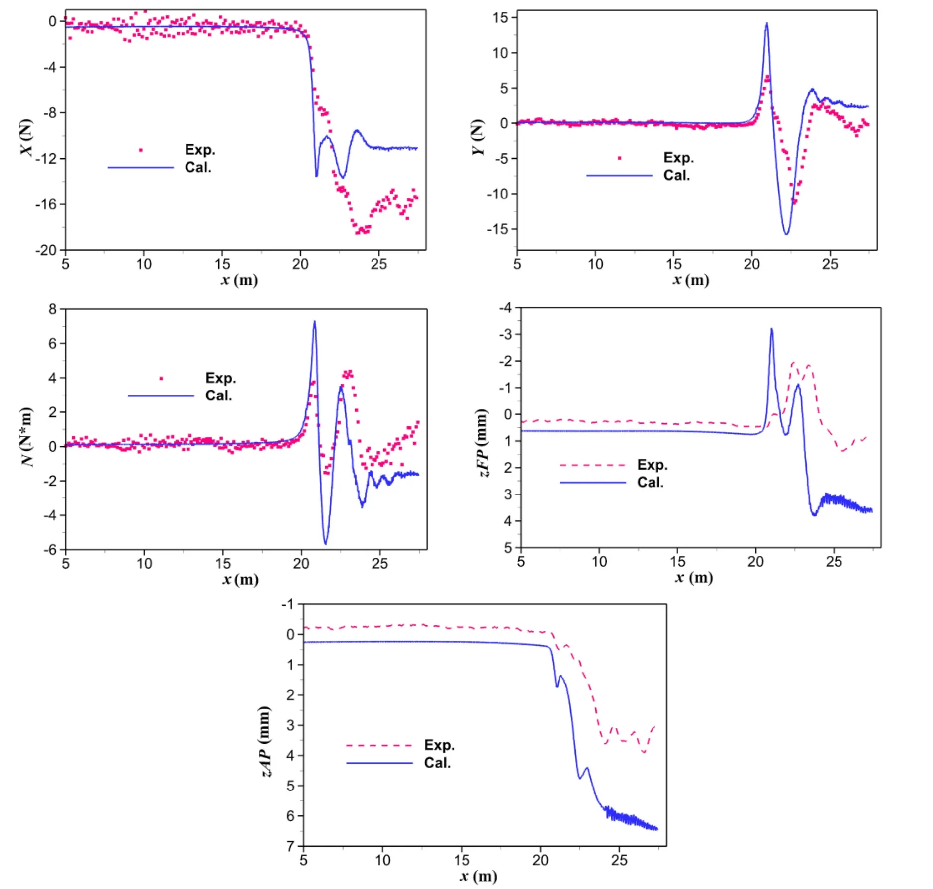
Fig.8 Calculated results compared with experimental data of test I
3.3 Effect of eccentricity in shallow water
From the numerical results of Tests G and I,we can see that the calculated values are different.So it can be deduced that both water depth and eccentricity have a significant effect on the hydrodynamic behaviors of ships passing through a lock.Numerical results under different h/T and eccentricity△y are obtained and analyzed to investigate the effects of water depth and eccentricity.The ship speed v is 0.15 m/s in all numerical calculation.As shown in Fig.9,water depth has a much larger effect on the hydrodynamic quantities than eccentricity,and eccentricity has a large effect on the hydrodynamic quantities when the bow of the ship model reaches the lock entrance.Besides,eccentricity yields a remarkably larger lateral force and yaw moment.As the ratio of water depth to draft decreases,the magnitudes of hydrodynamic forces and the vertical displacements of fore and aft perpendiculars increase.When the stern enters the lock,the trim angle decreases again to zero at h/T=1.2,but the ship remains a trim of bow up at h/T=1.1 and 1.05.

Fig.9 Effects of water depth and eccentricity on the hydrodynamic quantities
3.4 Effect of ship speed in shallow water
Numerical results at different h/T and v are calculated and analyzed to investigate the effect of ship speed in shallow water.As shown in Fig.10,both ship speed and water depth have a major effect on longitudinal force,lateral force and heel.Water depth has a significant effect on yaw moment and trim,while ship speed has a larger effect on sinkage.

Fig.10 Effects of water depth and ship speed on the hydrodynamic quantities
4 Conclusions
A numerical study on the hydrodynamic interaction between ship and lock is carried out by using an unsteady RANS solver.Hydrodynamic forces acting on a ship passing a lock in shallow water are calculated.The lateral force and yaw moment are evaluated with good accuracy in comparison with the experimental data.The effects of water depth,ship speed and eccentricity on the hydrodynamic force and moment and vertical displacements of fore and aft perpendiculars are investigated.Both the water depth and ship speed have a major influence on the hydrodynamic quantities and the eccentricity also has a significant influence when the bow of ship model just begins to enter the lock.The magnitudes of hydrodynamic forces and ship squat increase as water depth decreases and ship speed increases.When the stern enters the lock,the ship remains a trim of bow up in the condition of h/T=1.05 and 1.1.Meanwhile,water depth has a major effect on trim and ship speed has a major effect on sinkage.The present numerical method can qualitatively estimate the ship behaviors in a lock in shallow water.This study can provide some guidance on safe maneuvering and control of ships passing through a lock.
The authors would like to express their sincere thanks to the Knowledge Centre Manoeuvring in Shallow and Confined Water(Flanders Hydraulics Research&Ghent University)for providing the model test data.
[1]Choi H S,Mei C C.Wave resistance and squat of a slender ship moving near the critical speed in restricted water[C]//Proceedings of the 5th International Conference on Numerical Ship Hydrodynamics.Hiroshima,Japan,1989:439-454.
[2]Chen X N,Sharma S D.A slender ship moving at a near-critical speed in a shallow channel[J].Journal of Fluid Mechanics,1995,291:263-285.
[3]Gu Min,Wu Chengsheng.CFD calculation for resistance of a ship moving near the critical speed in shallow water[J].Journal of Ship Mechanics,2005,9(6):40-47.
[4]Huang Chengtao.Numerical calculate for viscous flow about a swirling ship in shallow water[D].Master thesis,Huazhong University of Science and Technology,Wuhan,China,2007.
[5]Verwiligen J,Richter J.Analysis of full ship types in high-blockage lock configurations[C]//Proceedings of International Conference on Marine Simulation and Ship Maneuverability(MARSIM’12).Singapore,2012.
[6]Delefortrie G,Willems M,Laforce E,Vantorre M,De Mulder T,De Regge J,Wong J.Tank test of vessel entry and exit for third set of Panama locks[C]//Proceedings of the International Navigation Seminar following PIANC AGA 2008.Beijing,China,2008:517-523.
[7]Delefortrie G,Willems M,Vantorre M,Laforce E.Behavior of post panama vessels in the Third Set of Panama locks[C]//Proceedings of International Conference on Marine Simulation and Ship Maneuverability(MARSIM’09).Panama City,Panama,2009.
[8]Van Kerkhove G,Vantorre M,Delefortrie G.Advanced model testing techniques for ship behaviour in shallow and confined water[C]//Proceedings of 1st International Conference on Advanced Model Measurement Technology for the EU Maritime Industry(AMT’09).Nantes,France,2009:158-172.
[9]Vantorre M,Delefortrie G,Mostaert F.Behaviour of ships approaching and leaving locks:Open model test data for validation purposes[R].Version 2.0.WL Rapporten,WL2012R815_08e.Flanders Hydraulics Research and Ghent University-Division of Maritime Technology:Antwerp,Belgium,2012.
[10]Thorenz C.Computational Fluid Dynamics in lock design-State of the art[C]//Proceedings of International Workshop on Innovations in Navigation Lock Design,PIANC.Brussels,Belgium,2009:10.
[11]Thorenz C.Numerical evaluation of filling and emptying systems for the new Panama Canal locks[C]//Proceedings of PIANC MMX Congress.Liverpool-UK,2010:77.
[12]De Mulder T.Computational Fluid Dynamics(CFD)in lock design:Progress and challenges[C]//Proceedings of International Workshop on‘What’s new in the design of navigation locks’,PIANC.New-Orleans,USA,2011:3-1.

- 船舶力学的其它文章
- DES Simulation of Flow Field of Propeller Tip Vortex
- Characteristics of Tendon Vortex Induced Vibrations Influenced by Platform Motion
- Mechanical Behavior of Flexible Jumper Installation in 3D Space
- Load-Compression Relationship of Incompressible Circular Rubber Pad Bonded between Rigid Plates
- Two-dimensional Eulerian-Lagrangian Modeling of Shocks on an Electronic Package Embedded in a Projectile with Ultra-high Acceleration
- Influence of Excitation Location on Sound Radiation of a Simple Duct Excited by Sound Source