
Numerical analysis of cavitation cloud shedding in a submerged water jet*
2016-12-26 06:51GuoyiPENGCongxinYANG杨从新YasuyukiOGUMASeijiSHIMIZU
水动力学研究与进展 B辑 2016年6期
Guoyi PENG, Congxin YANG (杨从新), Yasuyuki OGUMA, Seiji SHIMIZU
1. Department of Mechanical Engineering, College of Engineering, Nihon University, Koriyama, Fukushima 963-8642, Japan, E-mail: peng@mech.ce.nihon-u.ac.jp
2. School of Energy and Power Engineering, Lanzhou University of Technology, Lanzhou 730050, China
Numerical analysis of cavitation cloud shedding in a submerged water jet*
Guoyi PENG1, Congxin YANG (杨从新)2, Yasuyuki OGUMA1, Seiji SHIMIZU1
1. Department of Mechanical Engineering, College of Engineering, Nihon University, Koriyama, Fukushima 963-8642, Japan, E-mail: peng@mech.ce.nihon-u.ac.jp
2. School of Energy and Power Engineering, Lanzhou University of Technology, Lanzhou 730050, China
Focused on the unsteady behavior of high-speed water jets with intensive cavitation a numerical analysis is performed by applying a practical compressible mixture flow bubble cavitation model with a simplified estimation of bubble radius. The mean flow of two-phase mixture is calculated by unsteady Reynolds averaged Navier-Stokes (URANS) for compressible flow and the intensity of cavitation in a local field is evaluated by the volume fraction of gas bubbles whose radius is estimated with a simplified Rayleigh-Plesset equation according to pressure variation of the mean flow field. High-speed submerged water jet issuing from a sheathed sharp-edge orifice nozzle is treated. The periodically shedding of cavitation clouds is captured in a certain reliability compared to experiment data of visualization observation and the capability to capture the unsteadily shedding of cavitation clouds is demonstrated. The results demonstrate that cavitation takes place near the entrance of nozzle throat and cavitation cloud expands consequentially while flowing downstream. Developed bubble clouds break up near the nozzle exit and shed downstream periodically along the shear layer. Under the effect of cavitation bubbles the decay of core velocity is delayed compared to the case of no-cavitation jet.
cavitation, bubble dynamics, submerged water jet, two-phase flow, turbulent flow
Introduction
High-speed water jet injected into still water, which is called submerged water jet, has received much attention for its capacity of generating very high cavitation impact pressure in the collapse of cavitation bubbles and widely applied to such as peening of metal materials, decomposition of toxic substances and purification of sewages. Until now, many experimental studies have been made concerning jet driven pressure, shape and size of a nozzle, cavitation number etc. However, the structure of cavitating jet and the behavior of unsteady cavitation clouds are still unclear for the difficulty to observe the interior of cavitating flow[1,2]. For the purpose of performance prediction and optimum design of water jet devices numerical simulation of high-speed water jets with intensive cavitation becomes a task of more challenges[3].
Cavitation usually takes place in low-pressure re-gions of relative high velocity and cavitating flows in most industrial applications are turbulent ones. The flow dynamics at the interface formed between liquid and gas phases involves complex bubble-bubble and bubble-liquid interactions. These interactions are still not well understood in the closure region of cavities, where a distinct interface may not exist in the case of travelling cavitation cloud. Also, the near field of cavities reveals to be highly compressible due to the growth and collapse of bubbles while the far-field away from cavities is essentially incompressible. For the difficulty to consider all these different characteristics numerical simulations of cavitating flow have been conventionally performed by introducing certain simplifications on a special flow field concerned[4-8]. Most of numerical simulations of turbulent cavitating flow are based on unsteady Reynolds averaged Navier-Stokes (URANS) equations and cavitation models applied may be mainly classified into two-fluid and two-phase mixture flow method. Differing to the twofluid method, the pseudo one-fluid mixture flow method treats the cavitating fluid media as a locally homogeneous fluid mixture by neglecting the velocity slip between the liquid and gas phases. The physicalproperty of two-phase mixture is dependent on the volume fraction of gas phase, which varies greatly with oscillation of cavitation cloud. For evaluating the variation of gas volume fraction a supplementary equation estimating such as mass transfer between the two phases is usually introduced by employing a certain cavitation model. Thus, the computation of two-phase mixture models is much cheap since there is no need to treat the motion of a mass of bubbles separately. These methods are becoming more popular because they can be easily applied to turbulent flows encountered in most industrial applications[9,10].
Focused on the unsteady behavior of high-speed water jets with intensive cavitation a numerical analysis is performed by applying a compressible mixture flow bubble cavitation model in consideration of the effect of compressibility. The fluid media of cavitating flows are treated as a two-phase mixture of liquid and gas bubbles dispersing uniformly. The mean flow of two-phase mixture is calculated by URANS for compressible flow and the intensity of cavitation in a local field is evaluated by the volume fraction of gas bubbles whose radius is estimated with a simplified Rayleigh-Plesset equation. High-speed submerged water jet issuing from a sheathed sharp-edge orifice nozzle is treated and temporal variations of cavitating jet are investigated. The cavitation area predicted approximately agrees to experiment data of visualization observation and the unsteady behavior of periodical shedding of cavitation clouds is approximately captured.
1. Compressible mixture flow bubble cavitation model
Experimental observations show that cavitation occurred in high speed submerged water jets usually appears in the form of bubble clouds, and cavitation bubbles expand and contract rapidly corresponding to the variation of flow driving pressure. Thus, pressure transportation in cavitating fluid media become much different to that in homogeneous two-phase media for the effect of bubble oscillation. So, it becomes essential to evaluate the variation of fluid compressibility in intensive cavitating flows.
1.1 Compressibility of bubbly cavitation mixture
The fluid media of cavitating flow are taken as a two-phase mixture of working liquid and cavitation bubbles. The gas bubbles are supposed to disperse in the liquid phase uniformly and its volume faction is denoted as aG. The liquid volume fraction is written to be aL. Then, the density of two-phase mixture can be defined as follows by volume averaging.
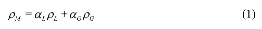
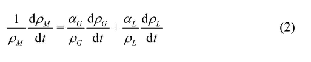
whereρdenotes fluid densities and the subscripts L, G andMrespectively do the liquid phase, the gas phase and the two-phase mixture. The temporal variation of mixture density can be obtained by taking the differential of above equation and it is then arranged to the following form.
Then, the compressibility of bubble-liquid mixture is defined as follows
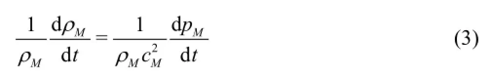
where
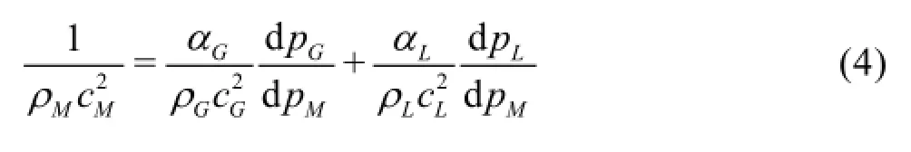
Herec denotes the mean sonic speed andpthe static pressure. Of course, the liquid pressure, the gas pressure and the mean mixture pressure vary complexly corresponding to the oscillation of a mass of bubbles in a local filed. Aiming to capture the general appearance of cavitation flow here we assume that liquid and gas pressures in a local field vary at the same order by neglecting the effect of surface tension. Then we reach that. In this way, Eq.(4) is simplified greatly and the compressibility of the bubbly mixture can be estimated directly by Eq.(4) according to the compressibility of liquid and gas phases.
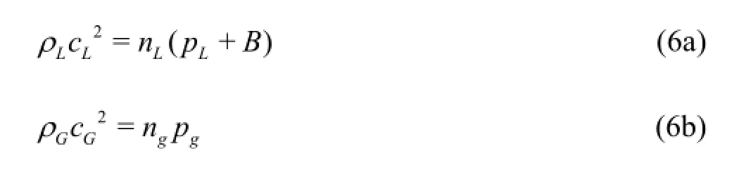
For determining the mean sonic speed in the mixture media both the liquid and the gas phases are supposed to work exponentially and the following state equations are applied.

where the superscriptn denote the specific heat ratio and the subscript 0 does a reference state which is taken to be the atmospheric one.B is a constant given to be 3.049×10⁸Pa. The gas phase included in a bubble is assumed to consist of non-condensation gas and vapor which are denoted by subscripted gandv, respectively. That is,pG=pg+pv. Then sonic speedsin liquid and gas phases are given as follows:
The pressure of non-condensation gas in a bubble is determined by the bubble radius Rb. That is to say,
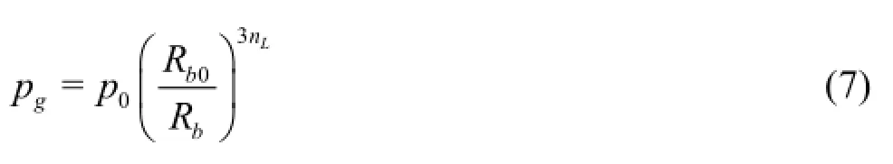
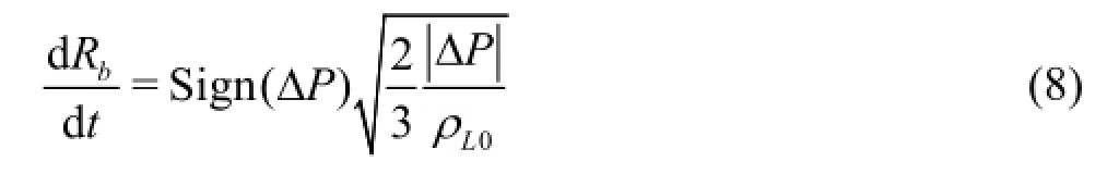
where Rb0denotes the initial bubble radius at the reference state. Of course, the bubble radius varies rapidly when cavitation occurs corresponding to a sharp decrease of surrounding liquid pressure. It may be solved by the Rayleigh-Plesset equation or similar ones[4]. But the calculation of these equations is time consuming for the high frequency of bubble oscillation. For the purpose of engineering applications the high frequency component of bubble oscillation is neglected in this work and the cavitation bubbles are treated as quasi-still one. Under the assumption ofthe Rayleigh-Plesset equation can be reduced greatly and the radius of cavitation may be estimated by solving the following simplified Rayleigh-Plesset equation.
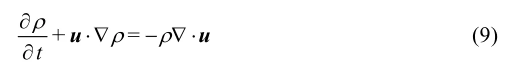
1.2 Governing equations for turbulent cavitating flow In consideration of the compressibility of activeting fluid mixture the URANS equations for compressible fluid are adopted as main flow governing equations. The variation of temperature caused by cavitation is thought to be very small in the whole flow field and the conservation equation of energy is omitted. Conservation equations of mass and momentum are given as follows in vector form. For convenience the subscriptM denoting the two-phase mixture is omitted hereafter.
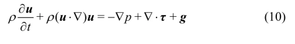
where g denotes the gravity, and τdenotes the stress tensor whose components are given as follows
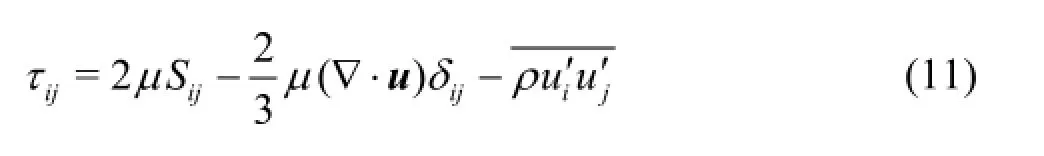
In this work the RNG k-εturbulence model[11,12]for high Reynolds number flow is adopted to take account of the turbulence effect and the Reynolds stress is given as follows
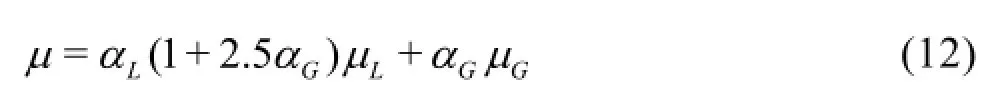
The eddy viscosity µtis defined by the turbulence energyk and the turbulence dissipation rateε, whose governing equations are omitted here. In intensive cavitation flow such as high speed water jets bubble clouds oscillates intensively and the eddy viscosity in a local area of bubble cloud may be greatly absorbed. In order to capture the unsteadily shedding of bubble clouds a density modification is introduced and then the eddy viscosity is evaluated by the following formula.
where χis an eddy viscosity modification coefficient considering theeffectofcavitation bubble cloud oscillation on theflow turbulent eddy viscosity[13].
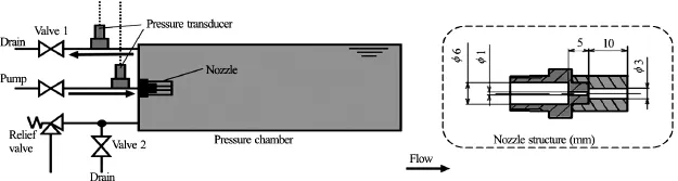
Fig.1 Scheme of cavitating water jet experiment device
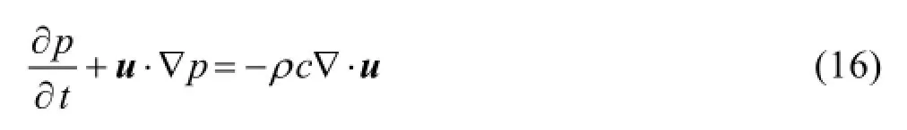
For closing Eq.(9) and Eq.(10) the mixture density is treated as a function of pressure and Eq.(3) relating the mixture density and pressure is used and then the following transport equation of the mixture pressure is derived.
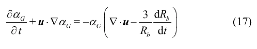
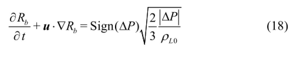
Furthermore, in order to estimate the variation of gas volume fraction, which determines the physic property of mixture media, the mass conversation of gas phase is employed and the following transport equation of aGis derived by considering the oscillation of bubble radius. As stated in proceed section cavitation bubbles oscillate while travel together with surrounding liquid flow. Thus, Eq.(8) governing the bubble radius is rewritten to the following form in consideration of the flow transportation.
1.3 Pressure-based CIP-CUP computation procedure
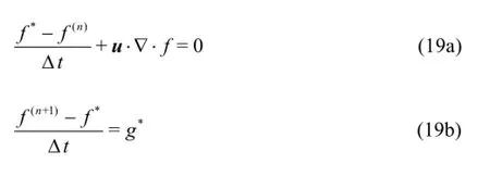
Equations (9), (10), (16)-(18) compose a set of main equations governing bubbly cavitating flow where the density of fluid mixture may vary sharply corresponding to expanding and contracting of cavitation bubbles. Considering the coexistence of strong compressible bubbly flow region and weak compressible liquid flow region in cavitating flow field these equations are solved simultaneously by applying the Cubic-Interpolated Propagation/Combined Unified Procedure (CIP-CUP) method[14,15]based on the time splitting technique.


2. Computational results and discussions
Water jet issuing from a submerged sharp-edged orifice nozzle was treated. Figure 1 shows the schematic diagram of water jet device where pressured clear water supplied by a plunger pump is injected into a closed cylindrical chamber to generate a submerged water jet. The pressure within the chamber can be adjusted to a given level up to 2.0 MPa and the output pressure of the plunger pump can be adjusted within its maximum pressure of 21.0 MPa according to the requirement of experiments. The throat diameter of the nozzle d =1.0 mmand the length of nozzlethroat is5d . A sheath to the nozzle is mounted at the exit of throat as shown in the scheme of nozzle structure. The inner diameter and the length of the sheath are3dand10d , respectively.
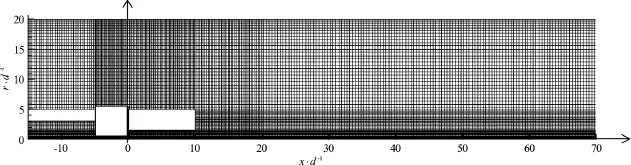
Fig.2 Domain and grids for numerical simulation
Figure 2 shows the computational domain taken for flow simulation. Focused on the axisymmetric structure at the upstream with in the sheath the simplification of axisymmetric flow was adopted and the computational domain was discretized with quadrilateral structure grid. The computation domain was taken from15d upstream of the nozzle entrance to70d downstream of the nozzle exit. The width of computational domain was taken to be25d in the radial direction. Concerning the boundary conditions a pressure condition was imposed at the inlet according to the given total pressure and the intensity of turbulence was given to be 1.0% of the inflow velocity. At the outlet a given static pressure was imposed and the Neumann condition was applied to other flow variables such as velocity etc. The wall boundaries of the cylindrical chamber, the nozzle as well as the sheath geometries were treated as no-slip walls by applying the wall function.
Figure 3 shows, as an example, the pattern of cavitation cloud shedding in a submerged water jet where the injection pressure Pi=1.1MPaand the chamber pressurePO=0.1MPa. The cavitation number is calculated to be 0.1 and the Reynolds number is about 5.0×10⁴for the concerned case. Figure 3(a) shows a sample of computational results when the jet flow gets to be well-developed, where the distribution of gas volume fraction aGis arranged in the form of contour map in a time sequence. In the pictures the local areas of highaGvalue denoted by red and dark green colors demonstrate axial sections of cavitation cloud including a mass of cavitation bubbles and the other areas of lower aGvalue (less than 0.005) denoted by blue color indicates the liquid phase (the initial gas volume fraction is set to be 0.001). The dark vectors denote the mean velocity in local flow field. According to the results we understand that a circular cavity consists of expanding bubbles is formed around the wall near the entrance nozzle throat. As shown in the pictures No. 2 and No. 3 the circular cavity expands streamwise and bubble clouds shed downstream along the shear layer. When the cavity reaches to its maximum as shown in the picture No. 3 it turns to contracts consequentially as shown in pictures No. 4 and No. 5. Pictures Nos. 5-9 show one more period of cavitation cloud shedding, and the dashed line does the periodical property of cavitation cloud shedding. The result demonstrates that cavitation clouds expand in the nozzle throat and then split into small blocks periodically while flow into the sheath. Brocken bubble clouds (aG=0.01-0.05)shed downstream along the shear layer around the jet.
Figure 3(b) shows an experimental result of visualization observation by high-speed video camera, where a sequence of pictures was taken at the imaging speed of 27 000 fps under the same flow condition as above[19]. Here a high lux light source was set at the opposite side of the camera and the pictures were taken under penetrating light condition. So, the area full of clear water is observed to be bright but the cloud of cavitation bubbles is observed to be dark areas since the cavitation cloud is almost impermeable to light. For the difficulty to observe the interior of the narrow nozzle throat visualization observation was focused on the flows in the sheath and the area of photograph was taken from the nozzle exit (x/ d =0) to the downstream of sheath exit (x/ d =14). As shown in the figure, cavitation clouds at the moment demonstrated by the first picture reach its minimum length in the axial direction. Then they expand gradually and shed downstream. As shown by the dashed line cavitation clouds caused by jet flow develop in the sheath and then shed downstream periodically[20]. Although a further detailed comparison is required the possibility to capture the unsteady behavior of bubble cloud shedding by the present computation model is demonstrated.
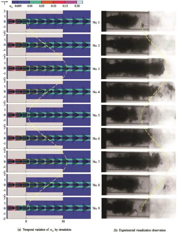
Fig.3 Shedding of cavitation cloud in a time sequence
Concerning the inner structure of cavitating jet, Figs.4(a) to 4(d) respectively show instantaneous distributions of gas volume fraction aG, dimensionless pressureflow turbulence kinetic energy k/and relative bubble radiusat the same moment by contour maps, where the vectors demonstrate the velocity profiles along the radial direction. As shown in Fig.4(a) a ring-like cavity appears near the wall boundary behind the nozzle throat entrance and it expands near to the sheath outlet as denoted by red and pink colors. Developed bubble clouds breaks up and shed downstream consequentially along the shear layer as denoted by the green color. Figure 4(b) demonstrates that pressure decreases sharply at the entrance of nozzle throat and its minimum reaches to 0.02 MPa in absolute pressure. Of course, pressure distribution is closely related to the distribution of aG,namely the breaking and sheading of bubble clouds in water jet. Comparing Fig.4(a) and 4(c) we understand that the turbulence energy is relatively low in the upstream shear layer within the nozzle where the value of aGis high (>0.05). Figure 4(d) shows that large bubbles appear mainly within the nozzle as well as the shear layer within the sheath, where developed bubble clouds break up and shed downstream periodically.
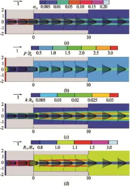
Fig.4 Flow distributions of cavitating water jet
According to Figs.4(a) and 4(d) we see that velocities at the upstream within the nozzle and the sheath vary sharply through the shear layer where the value of gas volume fraction is relatively high (>0.05). The reason can be concluded to the effect of cavitation bubbles, where the flow turbulence is absorbed by bubble oscillation and then the vortex viscosity decreases greatly in the shear layer containing numerous cavitation bubbles. Thus, the decay of core velocity may be delayed compared to the case of no-cavitation jet and it is advantageous to mechanically machining under submerged circumference.
Figure 5 shows the temporal variation of pressure at the position of x/ d =0.5and r/ d =0.49, which is located at the shear layer just behind the nozzle exit, by dashed blue line where p0denotes the atmospheric pressure. The result shows that pressure at the nozzle exit varies periodically at a relative low frequency and it may be considered as the effect of shear vortices formed at the nozzle exit and inlet. The timely averaged pressure decreased below to the atmospheric one and thus cavitation clouds often appear in this area. The dark solid line shows the temporal variation of mass flowrateq normalized by the mass flowrate at the condition of no-cavitation flow. The timely averaged mean value of the flowrate coefficient equals to 0.728 approximately and it is slightly smaller than the experimental result (approximately equals to 0.78) measured by weight method[19]. Compared to the probed pressure the flowrate fluctuates at a much high frequency but the amplitude of flowrate fluctuation is very small (<0.1%). It may be concluded to the influence of acoustic pressure wave which is dealt with in the present numerical simulation.
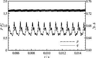
Fig.5 Temporal variation of flowrate coefficient and reference pressure
3. Conclusions
In consideration of the effect of flow compressibility caused by cavitation a practical compressible mixture flow bubble cavitation model is developed for the computation of turbulent cavitating flow by coupling a compressible mixture flow computation based on URANS with a simplified estimation of bubble radius. High-speed submerged water jet issuing from a sheathed orifice nozzle has been treated and the unsteady behavior of cavitation clouds is captured approximately in a certain reliability compared to experiment data of visualization observation.
Computational results show that: (1) Cavitation takes place mainly near the entrance of nozzle throat and cavitation cloud expands consequentially while flowing downstream. Expanded large bubbles appear within the nozzle and the shear layer in the sheath, where developed bubble clouds break up and shed downstream periodically along the shear layer. (2) Under the effect of cavitation bubbles the vortex viscosity decreases in shear layer containing bubble clouds and the decay of core velocity may be delayed compared to the case of no-cavitation jet.
Acknowledgements
This work was partly supported by JSPS, Grantin-Aid for Scientific Research (C) (Grant No. 26420124). The authors would like also to thank Mr. T. Ito et al., graduate students in our laboratory, for their assistance in experiments.
[1] Sato K., Taguchi Y., Hayashi S. High speed observation of periodic cavity behavior in a convergent-divergent nozzle for cavitating water jet [J]. Journal of Flow Control Measurement and Visualization, 2013, 1(3): 102-107.
[2] Li Y., Xu W. L., Zhang Y. L. et al. Cavitation bubbles collapse characteristics behind a convex body [J]. Journal of Hydrodynamics, 2013, 25(6): 886-894.
[3] Peng G., Shimizu S. Progress in numerical simulation of cavitating water jets [J]. Journal of Hydrodynamics, 2013, 25(4): 502-509.
[4] Qin Z., Bremhorst K., Alehossein H. Simulation of cavitation bubbles in a convergent-divergent nozzle water jet [J]. Journal of Fluid Mechanics, 2007, 573: 1-25.
[5] Iga Y., Konno T. Numerical analysis of the influence of acceleration on cavitation instabilities that arise in cascade [J]. International Journal of Fluid Machinery and Systems, 2012, 5(1): 1-9.
[6] Peng G., Shimizu, S., Fujikawa S. Numerical simulation of cavitating water jet by a compressible mixture flow method [J]. Journal of Fluid Science and Technology, 2011, 6(6): 499-509.
[7] Liu Z. H., Wang B. L., Peng X. X. et al. Calculation of tip vortex cavitation flows around three-dimensional hydrofoils and propellers using a nonlinear k-εturbulence model [J]. Journal of Hydrodynamics, 2016, 28(2): 227-237.
[8] Koukouvinis P., Bergeles G., Gavaises M. A cavitation aggressiveness index within the Reynolds averaged Navier Stokes methodology for cavitating flows [J]. Journal of Hydrodynamics, 2015, 27(4): 579-586.
[9] Tran T. D., Nennemann B., Vu T. C. et al. Investigation of cavitation models for steady and unsteady cavitating flow simulation [J]. International Journal of Fluid Machinery and Systems, 2015, 8(4): 240-253.
[10] Peng G., Okada K., Yang C. et al. Numerical simulation of unsteady cavitation in a high-speed water jet [J]. International Journal of Fluid Machinery and Systems, 2016, 9(1): 66-74.
[11] Yakhot V., Orszag S. A., Thangam S. et al. Development of turbulence models for shear flows by a double expansion technique [J]. Physics Fluids, 1992, 4(7): 1510-1520.
[12] Wilcox D. C. Turbulence modeling for CFD [M]. Sherman Oaks, California, USA: DCW Industries, 2002, 123-217.
[13] Peng G., Shimizu S., Fujikawa S. Numerical simulation of cavitating water jet by a compressible mixture flow method [J]. Journal of Fluid Science and Technology, 2011, 6(4): 499-509.
[14] Yabe T. Wang P. Y. Unified numerical procedure for compressible and incompressible fluid [J]. Journal of Physical Society of Japan, 1991, 60(7): 2105-2108.
[15] Ida M. An improved unified solver for compressible and incompressible fluids involving free surfaces: Part I. Convection [J]. Computer Physics Communications, 2000, 132(1): 44-65.
[16] Peng G., Ishizuka M., Hayama S. An improved CIP-CUP method for submerged water jet flow simulation [J]. JSME International Journal Series B: Fluids and Thermal Engineering, 2001, 44(4): 497-504.
[17] Peng G., Ito H., Shimizu S. Numerical simulation of highspeed cavitating water-jet issuing from a submerged nozzle [C]. Proceedings of the ASME Fluids Engineering Summer Meeting. Puerto Rico, USA, 2012, FEDSM2012-72438.
[18] Zhang L. X., Zhao W. G., Shao X. M. A pressure-based algorithm for cavitating flow computations [J]. Journal of Hydrodynamics, 2011, 23(1): 42-47.
[19] Peng G., Masuda K., Shimizu S. Characteristics of cavitating water jet issuing from a sheathed orifice nozzle [C]. Proceedings of FLUCOME 2013. Nara, Japan, 2013, OS7-01-3, 1-8.
[20] Zima P., Frst T., Sedl M. et al. Determination of frequencies of oscillations of cloud cavitation on a 2-D hydrofoil from high-speed camera observations [J]. Jornal of Hydrodynamics, 2016, 28(3): 369-378.
(Received June 22, 2016, Revised October 12, 2016)
* Biography:Guoyi PENG (1964-), Male, Ph. D., Professor

- 水动力学研究与进展 B辑的其它文章
- Development of an adaptive Kalman filter-based storm tide forecasting model*
- Numerical study on the effects of progressive gravity waves on turbulence*
- Experimental tomographic methods for analysing flow dynamics of gas-oilwater flows in horizontal pipeline*
- Energy saving by using asymmetric aftbodies for merchant ships-design methodology, numerical simulation and validation*
- Coupling of the flow field and the purification efficiency in root system region of ecological floating bed under different hydrodynamic conditions*
- Modelling hydrodynamic processes in tidal stream energy extraction*