液压驱动下肢助力外骨骼机器人膝关节结构设计及试验
2017-06-05 15:00靳兴来朱世强张学群朱笑丛潘忠强
农业工程学报 2017年5期
靳兴来,朱世强,张学群,朱笑丛,潘忠强
·农业装备工程与机械化·
液压驱动下肢助力外骨骼机器人膝关节结构设计及试验
靳兴来,朱世强※,张学群,朱笑丛,潘忠强
(浙江大学机械工程学院,杭州 310027)
液压驱动下肢助力外骨骼是一种典型的人机交互类机器人,在跟随人体行进的同时,可提高人的负重能力。为实现最优化的结构设计以降低对系统压强、液压缸尺寸的要求,通过仿生学分析人类正常步行时的步态数据,依据准拟人化设计准则,采用CAD设计软件、数值计算等方法,给出了液压驱动膝关节的设计过程,并通过MATLAB等仿真软件进行了验证。基于确定的模型参数,进行了结构设计及平台搭建,并进行了穿戴试验。仿真及试验结果表明,该方法设计的外骨骼膝关节可以满足步行及负重需求。在负重由10增加为20 kg时,即负重增加一倍时,膝关节的轨迹平均跟踪误差减小了0.05%,跟踪误差最大值增加了20.7%,但是相对于整个膝关节的活动范围,该误差仅占总活动范围的1.2%。该研究为优化液压驱动下肢助力外骨骼提供了参考方法,并可为直线执行器驱动外骨骼其他关节的优化设计提供参考。关键词:机器人;设计;优化;计算机仿真;液压驱动;膝关节;外骨骼;准拟人化
0 引 言
外骨骼机器人是指将人的智能、路径规划、自身平衡等能力与机器人的可负重、耐力强等优势相结合的一类机器人[1-2]。外骨骼技术最早出现于20世纪60年代,但自从美国加州大学伯克利分校研制成功第一款能源可携带的可穿戴式下肢助力外骨骼之后,作为一种典型的人机交互机器人[3-5],外骨骼机器人再次得到了国内外高校、研究院所乃至企业的重视。
Zoss等[6]在美国军方支持下研制成功了第一款下肢助力外骨骼BLEEX,该外骨骼旨在增强士兵背负重物的能力,之后相继推出了民用版的eLegs等型号;Kawamoto等[7-9]研发了HAL系列外骨骼,该系列的下肢版既可以用于增强穿戴者的负重能力,也可以用于瘫痪病人的康复训练;Toyama等[10]研制了农用版外骨骼,减轻农民劳动强度;电子科技大学于2015年成功研制出一款下肢外骨骼,该外骨骼主要是对瘫痪患者的助力,实现患者的站立行走[11-12]。Dollar等[13-14]则研制了膝关节被动助力外骨骼,由于没有动力元件,因此助力效果受到了限制。下肢外骨骼作为全身外骨骼的基础,其结构设计对系统性能有着显著影响。为了能达到较大的助力幅值,下肢助力外骨骼多采用液压驱动,其结构设计多采用仿生学设计方法[15-19]。外骨骼作为较新的机器人类别,日本首次将其应用于农业领域,外骨骼的发展及应用将推动农业的变革,显著降低农民劳作时的负担,增强农民的体力。
BLEEX通过对膝关节的机构建模,得出膝关节液压缸力臂与关节转角及安装位置的关系,根据临床步态数据(clinical gait analysis,CGA)数据得出的膝关节力矩-角度图,采用迭代法确定液压缸的安装位置,进而确定了膝关节的结构[20];赵彦峻等[21]着重分析了外骨骼机构确定之后的动力学仿真分析,并没有提出膝关节液压缸安装位置确定的方法;蒋靖[22]从机构静力学的角度分析了外骨骼机构,也未提及膝关节液压缸的设计方法。由于下肢助力外骨骼与穿戴者连接为一体,因此结构设计,尤其是液压执行器的安装位置的最优化设计非常重要,它会影响关节助力的幅值以及穿戴者的穿戴体验[23-24]。
本文将分析下肢助力外骨骼,优化膝关节的结构设计,通过仿真分析验证设计方法,并且在搭建的下肢助力外骨骼膝关节平台上进行穿戴试验。
1 仿生学设计
下肢外骨骼的机构设计可以被分为3类[2]:1)拟人化设计,下肢外骨骼的各关节与人体下肢关节一一对应,能够实现人体下肢相同的动作;2)准拟人化设计,下肢外骨骼的各关节从功能上与人体下肢各关节类似,能够实现与人体下肢类似的动作;3)非拟人化设计,下肢外骨骼的结构设计并不参考人体下肢关节。
为了在保证下肢外骨骼最大的灵活性同时又能降低整个系统的质量,本文采用了准拟人化的设计准则。需要参考人的下肢结构及运动信息,因此作如下假设:外骨骼的体积、质量及惯性等参数与人是类似的;外骨骼的步态能够满足人体运动步态的需求;外骨骼可以支撑自身的质量及一定的负载[25]。设计的下肢外骨骼单腿包含7个自由度,其中髋关节3个自由度、膝关节1个自由度、踝关节3个自由度,设计的三维结构如图1所示。
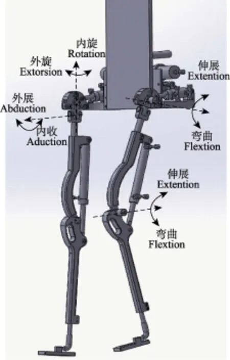
图1 液压驱动下肢助力外骨骼结构示意图Fig.1 Structural representation of hydraulic driven lower-limb power-assistance exoskeleton
统计数据指出人体下肢各关节的活动范围,结合图1的关节角度示意,定义膝关节或髋关节伸展角度为正,弯曲角度为负,设计的角度活动范围为:膝关节-10°~159°,髋关节-40°~110°。然而人体正常行走时的活动范围与上述数据并不一致,参考临床步态数据(75 kg,1.4 m/s),人体正常步行时的关节角度,如图2所示。常见的下肢助力外骨骼系统在设计时通常只考虑髋关节及膝关节的主动自由度,考虑到负载经由外骨骼传导至地面,增加膝关节在其他方向运动的驱动给整个系统质量及能耗带来的额外增加,本文所述的外骨骼只有髋关节和膝关节在矢状面内的自由度由液压缸驱动,其与自由度是被动自由度。因此图2只包含矢状面内的运动信息。
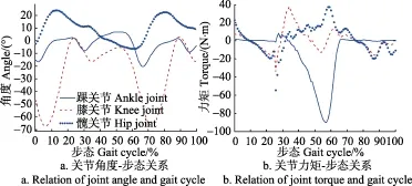
图2 临床步态数据Fig.2 Clinical gait data
通过对CGA曲线进行分析,可以得到图2所示的膝关节角度、力矩曲线。图2横坐标表示人体正常行走时,以一侧下肢从脚趾离地开始到该侧脚趾再次离地的一个完整步态周期。质量75 kg的人在以1.4 m/s的速度正常步行时,膝关节的活动范围大约在-5°~70°,考虑到膝关节其他弯曲状况的存在以及为了避免角度过大造成穿戴者的关节不舒服甚至受伤,本文设计的膝关节矢状面内的活动范围为0º~120º。
1.1 结构设计
膝关节的结构设计主要是液压执行器及其安装位置的设计。本文采用了准拟人化的设计准则,并且参考CGA数据进行结构设计,故膝关节的液压执行器需要产生比CGA力矩值更大的力矩以驱动外骨骼。由于液压缸是线性执行器,采用类似于人体肌肉分布的方法,将液压缸两端分别安装在大腿和小腿上[26-28]。
1.1.1 膝关节建模
图3是膝关节的几合模型。液压缸无杆腔在A端,有杆腔在B端。

图3 膝关节几何模型Fig.3 Geometric model of knee joint
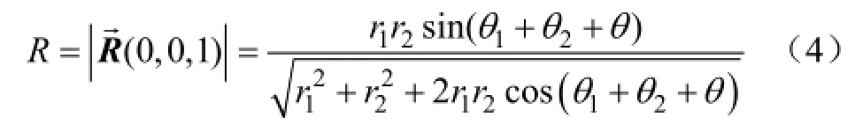
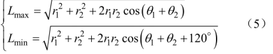
O代表膝关节旋转中心,x、y是建立的直角坐标系,定义图3中液压缸安装点的坐标A(x1,y1),B(x2,y2),并且定义OA=r1,OB=r2。可得
式中θ1、θ2表示液压缸在大腿杆、小腿杆上的安装角,(º);θ表示膝关节旋转角,(°)。
液压缸坐标向量为

根据膝关节角度的设计范围,满足θ∈(0°,120°),在该条件下,则有θ1+θ2≤60°。膝关节活动角度的弯曲角最大及伸展角最大时,分别对应了液压缸的最短长度及最长长度。
1.1.2 力矩分析
液压缸输出力矩由液压力以及力臂所决定,而力臂又受液压缸安装位置的影响,因此优化液压缸安装位置,将降低对系统压强的要求,有利于液压缸的选型和设计。假定液压缸尺寸已经确定,需要分析液压缸的安装位置,结合CAD软件对此进行定性分析,如图4所示。

图4 液压缸安装位置效果Fig.4 Effects of different mounting locations of cylinder
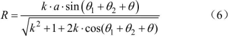
图4 中的坐标标号与图3含义相同。虚线AB表示膝关节伸展时,即θ=0°,液压缸的最大长度;虚线AB'表示膝关节弯曲最大角度时,即θ=120°,液压缸的最小长度。由图4可知,图4c中液压缸完全伸展及最大收缩时的方向变化较小,考虑到力的方向稳定性,选取图4c的布置方式,即r1>r2。基于以上分析,定义r1/r2=k,并且,k>1。结合图3,令r2=a cm,则有r1=k·a cm,代入式(4),得到力臂值如式(6)。
由式(6)借助MATLAB可以得到力臂值R与膝关节角度 (θ1+θ2+θ)和系数k的关系,如图5a所示。由于下肢外骨骼采用准拟人化设计准则,可以参考75 kg体质量人群的CGA数据,通过图2b中的力矩曲线,可知在膝关节弯曲约20°时,即θ=20°,力矩最大,由于外骨骼膝关节的最大活动范围120°可知,力矩最大点位于图5a中的平滑区域C,在该区域,k≥5后,力臂值R近似于直线,考虑到实际安装尺寸的限制,因此得k=5。接下来需要确定θ1及θ2,结合k=5和式(6)并借助MATLAB可得(θ1+θ2+θ)与力臂的对应关系,如图5b所示,力臂值R随着角度(θ1+θ2+θ)的增大先增大后减小,类似于开口向下的抛物线。
当θ1+θ2+θ=103°时,力臂值最大,最理想的情况是当θ=20°时,力臂值最大,然而此时θ1+θ2=80°,与θ1+ θ2≤60°相矛盾,因此,可知无法实现力臂值最大值与膝关节力矩最大值在同一弯曲角下存在。结合图5可知,(θ1+θ2)越大,在θ=20°时越接近于力臂值最大值,因此可得出θ1+θ2=60°。
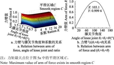
图5 力臂曲线分析Fig.5 Graphic analysis of arm of force
1.1.3 液压缸倾角分析
为了分析θ1及θ2取值的影响,再次借助CAD软件进行定性分析,图6a表示θ2>θ1,图6b表示θ2≤θ1。

图6 液压缸不同安装角的效果Fig.6 Effects of different mounting angles of hydraulic cylinder
不同的θ1取值,影响液压缸的倾斜角,比较图6可得出:液压缸在大腿杆上的安装倾角不应比在小腿杆上的安装角大,否则不仅液压缸存在较大的倾斜角,而且导致液压缸大腿处的安装→位置与大腿相距较远,穿戴不方便。为此,定义向量,可得出液压缸的倾角方程

结合式(7),借助MATLAB可得图7。由图7可知,在θ1>10°后,随着膝关节的弯曲,液压缸的倾角逐渐变大方向一致,同时随着θ1变大,在相同膝关节弯曲角度下,液压缸倾角的变化也更加剧烈,因此,基于图7,选取:θ1=15°,θ2=45°。
由式(6)可知,a取值越大,力臂越大,但同样液压缸的长度也会越大,同时a的取值还受下肢长度的限制。统计数据表明人体下肢的尺寸关系如式 (8)。例如当人体身高H为175 cm时,L大腿为43 cm,L小腿为43 cm。
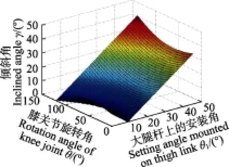
图7 液压缸倾角图Fig.7 Pitch angle of hydraulic cylinder
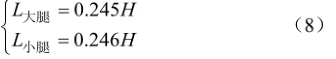
式中L大腿和L小腿分别为大腿和小腿的长度,cm;H为人体身高,cm。
由式(8),结合图3有:r1cosθ1<41,a<8.5,选取a=5 cm,根据图3,可列出液压缸的最大推力及最大拉力公式,如式(9)所示。
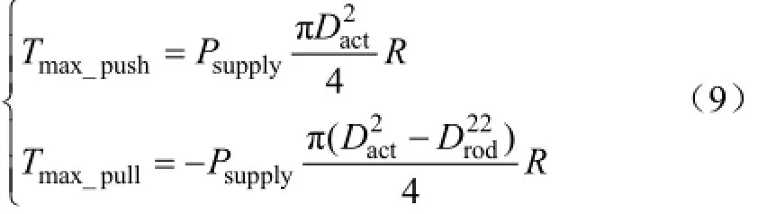
式中Tmax_push代表液压缸所产生的最大推力,Tmax_push代表液压缸所产生的最大拉力,Psupply代表系统压力,Dact代表无杆腔的杆径,Drod代表活塞杆杆径。
1.1.4 参数确定
选取常用液压压强6.5 MPa,并将图2中得到的
θ =20°时Tmax=60 N·m代入式(9),可得缸径Dact=1.94 cm,取整为:Dact=2 cm。同理根据图2弯曲时的最大力矩:θ=0°,Tmax=40 N·m代入式(9),可得活塞杆杆径Drod= 0.988 7 cm,取整为Drod=0.9 cm。
1.2 结构仿真
为了确保液压缸的尺寸及安装位置能够在人体步行时提供足够的力矩,借助MATLAB进行仿真验证。图8中显示CGA曲线统计的人体膝关节所需力矩曲线被本文设计的膝关节所提供的弯曲力矩和伸展力矩曲线包围。
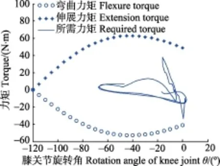
图8 设计机构产生的力矩与所需力矩对比Fig.8 Comparison of torque produced by designed knee joint and desired torque
2 试验与分析
基于上述分析确定的液压缸尺寸及安装位置,搭建了可穿戴式下肢助力外骨骼平台,设计加工的膝关节结构如图9所示。并设计了滑模控制器进行了膝关节位置跟踪的穿戴试验[29-33],穿戴者分别在外骨骼背板质量约为10 kg(工况一)及再加额外质量10 kg(工况二)2种工况下进行试验。为了使试验具有可对比性,穿戴者尽量做2次相同的运动,图10a为膝关节位置曲线,图10b为2次的轨迹跟踪误差曲线。
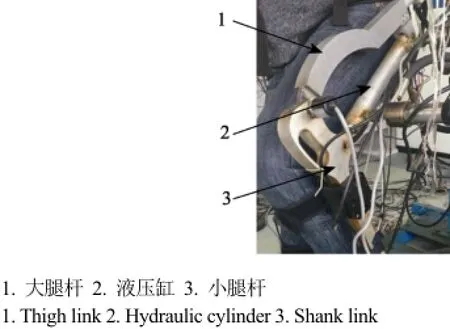
图9 膝关节结构图Fig.9 Structure block of knee joint

图10 膝关节位置跟踪试验Fig.10 Position tracking experiments of knee joint
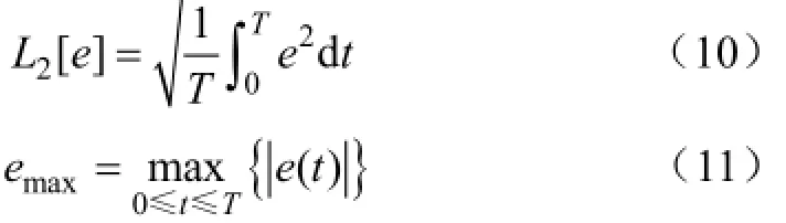
分析上述试验数据,并定义2个评价指标[34],如式(10)与式(11)。式中L2[e]表示轨迹平均跟踪误差,(°);emax表示最大跟踪误差,(°);T为运行时间,(s);e(t) 为位置跟踪误差。
穿戴下肢外骨骼后,在负重由10变为20 kg时,膝关节的轨迹平均跟踪误差并没有增加,却由0.330 7°降低到0.329 2°,缩小了0.05%;最大误差由0.514 8°增加到0.621 4°,增加了20.7%,但是相对于整个膝关节的活动范围,该误差仅占总活动范围的1.2%,且与负载增加了100%相比,也可忽略。从侧面反映了机械结构的有效性。
3 结 论
本文主要研究了液压驱动下肢助力外骨骼膝关节的结构优化,通过理论分析和图形仿真提出了一套液压助力膝关节结构设计、优化的方法。
1)从分析人体正常步行时的步态数据入手,采用准拟人化方法指导下肢外骨骼设计,明确了下肢外骨骼的主被动关节布置及相应的活动范围。
2)搭建了液压驱动膝关节的示意图,并运用CAD软件、数值分析及仿真软件等方法详细探讨了液压驱动下肢外骨骼膝关节的设计依据,得出参数优化的方法,最终得出优化的膝关节布局,降低了对液压系统的要求。
3)进行了仿真和穿戴试验,仿真表明所设计的液压助力膝关节能够满足人体膝关节的力矩需求,试验则表明在负载增加一倍的情况下,膝关节穿戴后跟踪误差最大值增加了约20.7%,但平均跟踪误差减小了0.05%,说明优化后的膝关节在关节穿戴试验时跟随效果基本不受负载的影响。
4)基于所设计的下肢助力外骨骼的膝关节,仿真和试验均表明本文所提方法能够有效指导液压驱动下肢助力外骨骼膝关节的最优设计,并且该方法可拓展至直线执行器驱动的外骨骼其他主动关节设计中。
[1] Kazerooni H, Steger R. The Berkeley lower extremity exoskeleton[J]. Journal of Dynamic Systems, Measurement, and Control, 2006, 128(1): 14-25.
[2] Lee H, Kim W, Han J, et al. The technical trend of the exoskeleton robot system for human power assistance[J]. International Journal of Precision Engineering and Manufacturing, 2012, 13(8): 1491-1497.
[3] Chen B, Ma H, Qin L Y, et al. Recent developments and challenges of lower extremity exoskeletons[J]. Journal of Orthopaedic Translation, 2016(5): 26-37.
[4] Kazerooni H. A review of the exoskeleton and human augmentation technology[C]//ASME 2008 Dynamic Systems and Control Conference, 2008, 1539-1547.
[5] Yang C J, Zhang J F, Chen Y, et al. A review of exoskeletontype systems and their key technologies[J]. Proceedings of the Institution of Mechanical Engineers, Part C: Journal of Mechanical Engineering Science, 2008, 222(8): 1599-1612.
[6] Zoss A. Actuation Design and Implementation for Lower Extremity Human Exoskeletons[D]. Berkeley: University of California, 2006.
[7] Kawamoto H, Taal S, Niniss H, et al. Voluntary motion support control of robot suit HAL triggered by bioelectrical signal for hemiplegia[C]//Engineering in Medicine and Biology Society (EMBC), 2010 Annual International Conference of the IEEE, 2010: 462-466.
[8] Kawamoto H, Sankai Y. Power assist method based on phase sequence and muscle force condition for HAL[J]. Advanced Robotics, 2005, 19(7): 717-734.
[9] Kawamoto H, Sankai Y. Power assist method based on phase sequence driven by interaction between human and robot suit[C]//13th IEEE International Workshop on Robot and Human Interactive Communication, 2004: 491-496.
[10] Toyama S, Yamamoto G. Development of Wearable-agrirobot mechanism for agricultural work[C]//2009 IEEE/RSJ International Conference on Intelligent Robots and Systems, 2009: 5801-5806.
[11] 张倩. 下肢外骨骼康复机器人的机构设计与分析[D]. 成都:电子科技大学,2013.
Zhang Qian. Mechanism Design and Analysis of the Lower Limb Exoskeleton Rehabilitation Robot[D]. Chengdu: University of Electronic Science and Technology of China, 2013.
[12] 王强. 可穿戴下肢外骨骼康复机器人机械设计与研究[D].成都:电子科技大学,2014.
Wang Qiang. Mechanism Design and Research of the Wearable Lower Limb Exoskeleton Rehabilitation Robot[D]. Chengdu: University of Electronic Science and Technology of China, 2014.
[13] Dollar A M, Herr H. Design of a quasi-passive knee exoskeleton to assist running[C]//IEEE/RSJ International Conference on Intelligent Robots and Systems, 2008: 747-754.
[14] Lambrecht B G, Kazerooni H. Design of a semi-active knee prosthesis[C]//IEEE International Conference on Robotics and Automation, 2009: 639-645.
[15] 杨巍,张秀峰,杨灿军,等. 基于人机5杆模型的下肢外骨骼系统设计[J]. 浙江大学学报,2014,48(3):430-435,444.
Yang Wei, Zhang Xiufeng, Yang Canjun, et al. Design of a lower extremity exoskeleton based on 5-bar human machine model[J]. Journal of Zhejiang University, 2014, 48(3): 430-435, 444. (in Chinese with English abstract)
[16] 王善杰. 下肢可穿戴外骨骼机器人仿人机构设计与运动控制研究[D]. 合肥:合肥工业大学,2015.
Wang Shanjie. Humanoid Mechanism Design and Motion Control of Lower Extremity Wearable Exoskeleton Robot[D]. Hefei: Hefei University of Technology, 2015.
[17] Huo W G, Mohammed S, Moreno J C, et al. Lower limb wearable robots for assistance and rehabilitation: A state of the art[J]. IEEE Systems Journal, 2016, 10(3): 1068-1081.
[18] Chu A. Design of the Berkeley Lower Extremity Exoskeleton[D]. Berkeley: University of California, 2005.
[19] 荣誉,金振林,崔冰艳. 六足农业机器人并联腿构型分析与结构参数设计[J]. 农业工程学报,2012,28(15):9-14.
Rong Yu, Jin Zhenlin, Cui Bingyan. Configuration analysis and structure parameter design of six-leg agricultural robot with parallel-leg mechanism[J]. Transactions of the Chinese Society of Agricultural Engineering (Transactions of the CSAE), 2012, 28(15): 9-14. (in Chinese with English abstract)
[20] 李研彪,刘毅,赵章风,等. 基于空间模型技术的拟人机械腿的运动学传递性能分析[J]. 农业工程学报,2013,29(2):17-23.
Li Yanbiao, Liu Yi, Zhao Zhangfeng, et al. Kinematics transmission analysis on anthropopathic mechanical leg based on spatial model technique[J]. Transactions of the Chinese Society of Agricultural Engineering (Transactions of the CSAE), 2013, 29(2): 17-23. (in Chinese with English abstract)
[21] 赵彦峻,徐诚. 人体下肢外骨骼设计与仿真分析[J]. 系统仿真学报,2008,20(17):4756-4759,4766.
Zhao Yanjun, Xu Cheng. Design and simulation of human lower extremity exoskeleton[J]. Journal of System Simulation, 2008, 20(17): 4756-4759, 4766. (in Chinese with English abstract)
[22] 蒋靖. 下肢助力外骨骼机构设计与研究[D]. 哈尔滨:哈尔滨工业大学,2012.
Jiang Jing. Research and Mechanism Design of Lower Limb Power Exoskeletons[D]. Harbin: Harbin Institue of Technology, 2012.
[23] 严华,杨灿军,陈杰. 上肢运动康复外骨骼肩关节优化设计与系统应用[J]. 浙江大学学报,2014,48(6):1086-1094.
Yan Hua, Yang Canjun, Chen Jie. Optimal design on shoulder joint of upper limb exoskeleton robot for motor rehabilitation and system application[J]. Journal of Zhejiang University, 2014, 48(6): 1086-1094. (in Chinese with English abstract)
[24] 贾山,韩亚丽,路新亮,等. 基于人体特殊步态分析的下肢外骨骼机构设计[J]. 机器人,2014,36(4):392-401,410.
Jia Shan, Han Yali, Lu Xinliang, et al. Design of lower extremity exoskeleton based on analysis on special human gaits[J]. Robot, 2014, 36(4): 392-401, 410. (in Chinese with English abstract)
[25] Kim W, Lee H, Kim D, et al. Mechanical design of the Hanyang exoskeleton assistive robot (HEXAR)[C]//14thInternational Conference on Control, Automation and Systems (ICCAS), 2014: 479-484.
[26] Zoss A, Kazerooni H, Chu A. On the mechanical design of the berkeley lower extremity exoskeleton (BLEEX)[J]. IEEE/ASME Transactions on Mechatronics, 2005, 11(2): 128-138.
[27] Chu A, Kazerooni H, Zoss A. On the biomimetic design of the berkeley lower extremity exoskeleton[C]//IEEE International Conference on Robotics and Automation, 2005: 4345-4352.
[28] Miao Y J, Gao F, Pan D L. Mechanical design of a hybrid leg exoskeleton to augment load-carrying for walking[J]. International Journal of Advanced Robot Systems, 2013(10): 1-11.
[29] 陈庆诚,朱世强,Mittal R,等. 基于POE的动力学建模与快速非奇异终端滑模控制[J]. 农业机械学报,2015,46(6):310-318.
Chen Qingcheng, Zhu Shiqiang, Mittal R, et al. Dynamic modeling based on poe and non-singular terminal sliding mode control[J]. Transactions of the Chinese Society of Agricultural Machinery, 2015, 46(6): 310-318. (in Chinese with English abstract)
[30] 焦俊,孔文,王强,等. 基于输入模糊化的农用履带机器人自适应滑模控制[J]. 农业机械学报,2015,46(6):14-19,23.
Jiao Jun, Kong Wen, Wang Qiang, et al. Self-adaptive sliding mode control based on input fuzzy for agricultural tracked robot[J]. Transactions of the Chinese Society of Agricultural Machinery, 2015, 46(6): 14-19, 23. (in Chinese with English abstract)
[31] Eker I, Akinal S A. Sliding mode control with integral augmented sliding surface: Design and experimental application to an electromechanical system[J]. Electrical Engineering , 2008, 90(3): 189-197.
[32] Eker I. Sliding mode control with PID sliding surface and experimental application to an electromechanical plant[J]. Isa Transactions, 2006, 45(1): 109-118.
[33] 陈志伟,金波,朱世强,等. 液压驱动仿生多足机器人单腿设计与试验[J]. 农业工程学报,2016,32(5):36-42.
Chen Zhiwei, Jin bo, Zhu Shiqiang, et al. Design and experiment of single leg of hydraulically actuated bionic multi-legged robot[J]. Transactions of the Chinese Society of Agricultural Engineering (Transactions of the CSAE), 2016, 32(5): 36—42.(in Chinese with English abstract)
[34] 潘忠强. 助力外骨骼下肢控制技术研究[D]. 杭州:浙江大学,2015.
Pan Zhongqiang. Control Technique Research on Power-Assistance Exoskeleton's Lower Extremity[D]. Hangzhou: Zhejiang University, 2015.
Structure design and experiment of knee joint of hydraulic driven lower-limb power-assistance exoskeleton robot
Jin Xinglai, Zhu Shiqiang※, Zhang Xuequn, Zhu Xiaocong, Pan Zhongqiang
(College of Mechanical Engineering, Zhejiang University, Hangzhou 310027, China)
As a kind of typical human-machine interaction robot, the powered lower-limb exoskeleton driven by hydraulics can augment wearer’s power while following wearer. This kind of exoskeleton has a broad application in military field, rescue occasions, and so on, however, there are still many technical difficulties which need to be studied, such as structure optimization. There are 3 kinds of design concepts among the exoskeleton structure design. To guarantee the flexibility and decrease the dead weight of exoskeleton, quasi-anthropomorphic design was adopted, which means the lower-limb exoskeleton is similar to leg but does not need one-to-one match. According to quasi-anthropomorphic design rule, 7 degrees of freedom for single leg were set to satisfy the freedom need of wearer. Among these 7 degrees of freedom, only 2 degrees are active which are located in sagittal plane of knee joint and hip joint. During designing the active freedom of knee joint, the core parameters are the size of hydraulic cylinder and the torque which can be produced. So it is significant to study a method which can lead to a minor size of hydraulic cylinder while producing the same torque. To optimize the structure of knee joint and its hydraulic system, the computer aided design (CAD) method and the numerical calculation method were adopted to design the structure of the hydraulic cylinder and its installation position. According to the schematic diagram of structure, the relationship of torque, arm of force, and installation position was built. Design indicators were obtained through analyzing the clinical gait analysis (CGA) data, which was widely used in lower-limb exoskeleton research. To find out the optimized parameter, MATLAB was used to present graphics which depicted the nonlinear relationship which was built before. According to the optimization method, the hydraulic driven knee joint of the lower limb exoskeleton was designed and assembled. During the normal walking phase, there are 2 kinds of torques in knee joint, which contain flexure torque and extension torque. Flexure torque is used to bend shank to avoid the collision of foot and floor while extension torque is used to extend shank to drive the body forward. The both kinds of torques are also important for a person to walk. So simulations were designed to compare the torque produced by hydraulic driven knee joint and the torque needed in normal walking which was got through CGA data. The simulation found that the designed hydraulic driven knee joint could meet the torque demand. Meanwhile, the comparison experiments were also designed and implemented. Hydraulic driven knee joint was driven to follow the motion of wearer in 2 conditions. In the first condition, the wearer just needed to bear the exoskeleton’s own weight, which was about 10 kg. In the second condition, another 10 kg load was added on the exoskeleton. It should be noted that all load was transferred to the ground through lower-limb exoskeleton, which meant the added load wouldn’t add other burden to wearer. This is the work mechanism of powered lower-limb exoskeleton. In the comparison experiments, the wearer was demanded to move a similar trajectory while it was impossible to move the same trajectory. Experiments showed that the average error was decreased by 0.05% while the maximum error was increased by 20.7%. Considering the load was increased by 100% and the motion range was large, these results clear demonstrated how the designed hydraulic driven knee joint satisfied the demand of walking with load. In conclusion, a method is proposed to fulfill the optimization of the knee joint structure of the hydraulic driven lower-limb exoskeleton, and it can obviously instruct other joint design of exoskeleton which is driven by linear actuator such as linear motor and electric cylinder.
robots; design; optimization; computer simulation; hydraulic driven; knee joint; exoskeleton; quasi- anthropomorphic
10.11975/j.issn.1002-6819.2017.05.004
TH137
A
1002-6819(2017)-05-0026-06
靳兴来,朱世强,张学群,朱笑丛,潘忠强. 液压驱动下肢助力外骨骼机器人膝关节结构设计及试验[J]. 农业工程学报,2017,33(5):26-31.
10.11975/j.issn.1002-6819.2017.05.004 http://www.tcsae.org
Jin Xinglai, Zhu Shiqiang, Zhang Xuequn, Zhu Xiaocong, Pan Zhongqiang. Structure design and experiment of knee joint of hydraulic driven lower-limb power-assistance exoskeleton robot[J]. Transactions of the Chinese Society of Agricultural Engineering (Transactions of the CSAE), 2017, 33(5): 26-31. (in Chinese with English abstract)
doi:10.11975/j.issn.1002-6819.2017.05.004 http://www.tcsae.org
2016-10-24
2016-12-16
国家自然科学基金创新研究群体资助项目(51521064);浙江省自然科学基金资助项目(LY13E050001);杭州市重大科技创新资助项目(20132111A04)
靳兴来,男,山东泰安人,博士生,主要从事外骨骼机器人的系统开发及控制系统研究。杭州 浙江大学机械工程学院,310027。
Email:21125069@zju.edu.cn
※通信作者:朱世强,男,浙江义乌人,教授,博士,主要从事机器人技术研究。杭州 浙江大学机械工程学院,310027。Email:sqzhu@zju.edu.cn
猜你喜欢
农业装备与车辆工程(2022年4期)2022-10-31
现代仪器与医疗(2022年4期)2022-10-08
小哥白尼(野生动物)(2021年12期)2021-03-29
重型机械(2020年2期)2020-07-24
轻兵器(2019年5期)2019-06-21
制造技术与机床(2017年5期)2018-01-19
大众健康(2016年3期)2016-05-31
筑路机械与施工机械化(2014年2期)2014-03-01
组合机床与自动化加工技术(2014年10期)2014-03-01