
Reduced technique for modeling electromagnetic immunity on braid shielding cable bundles∗
2017-08-30 08:25PeiXiao肖培PingAnDu杜平安BaoLinNie聂宝林andDanRen任丹
Chinese Physics B 2017年9期
关键词:宝林
Pei Xiao(肖培),Ping-An Du(杜平安),Bao-Lin Nie(聂宝林),and Dan Ren(任丹)
Department of Mechatronics Engineering,University of Electronic Science and Technology of China,Chengdu 611731,China
Reduced technique for modeling electromagnetic immunity on braid shielding cable bundles∗
Pei Xiao(肖培),Ping-An Du(杜平安)†,Bao-Lin Nie(聂宝林),and Dan Ren(任丹)
Department of Mechatronics Engineering,University of Electronic Science and Technology of China,Chengdu 611731,China
In this paper,an efficient multi-conductor simplification technique is proposed to model the electromagnetic immunity on cable bundles within a braid shielding structure over a large frequency range.By grouping together the conductors based on the knowledge of Z-Smith chart,the required computation time is markedly reduced and the complexity of modeling the completely shielding cable bundles is significantly simplified with a good accuracy.After a brief description of the immunity problems in shielding structure,a six-phase procedure is detailed to generate the geometrical characteristics of the reduced cable bundles.Numerical simulation is carried out by using a commercial software CST to validate the efficiency and advantages of the proposed approach.The research addressed in this paper is considered as a simplified modeling technique for the electromagnetic immunity within a shielding structure.
cable bundles,electromagnetic immunity,braid shielding structure,numerical simulation
1.Introduction
In modern industrial domains such as the automotive industry and aviation industry,reliably and efficiently generating a full numerical model of complex real systems has become a difficult task for the designers.[1,2]Numerical modeling method and simulation have been widely used in the electromagnetic compatibility(EMC)analysis.[3–5]It requires a reliable model of the target electrical structure,in particular the model of the cable harness.[6,7]In order to simplify the structural modeling and improve the analytic efficiency,this paper focuses on the reduction technique of braid shielding cable bundles.
The electromagnetic(EM)coupling mechanism on cable harnesses in a real system has been widely studied based on the theory of multiconductor transmission line networks (MTLN).[8–13]Compared with numerical simulation in calculating EM fields,the MTLN formalism performs better accuracy and needs less computation time.Unfortunately,the MTLN model behaves inefficiently at high frequencies due to the appearance of nonquasi-TEM modes.Hence,many researchers put forward hybrid methods to handle the EM coupling situations on cable harnesses.[14,15]In addition,some researchers adopted measurement approaches to deal with their modeling.[16]However,despite the rapid improvement in computer performance,it is still impossible to perform an accurate computation on the complete model of the whole realistic cable harnesses.
Previous work on elaborating an EMC model for the cable harness with so called“equivalent cable bundle method (ECBM)”has been reported.On the assumption that the common-mode(CM)response is more critical than the differential-mode response for the EM coupling problems, the ECBM for modeling CM currents on cable bundles at high frequency for automotive applications is proposed for the first time.[17]Then,this technique is extended to model EM emissions of complex cable bundles.[18]Recently,the ECBM has been adopted to model the crosstalk of complex cable bundles[19,20]and calculate the conducted rear-door disturbances at a vehicle level with a huge number of wires.[21,22]
In this paper,an efficient reduced technique is proposed to handle the modeling of the EM immunity prediction of complex cable bundles within a braid shielding structure.For this new kind of application,the main assumption is the same as that addressed in Ref.[17].The rest of this paper is organized as follows.Section 2 presents the equivalent process of the simplification technique in detail,which contains conductor grouping and equivalent geometrical characteristics.In Section 3,we validate the proposed method with a model of braid shielding 14-conductors by using CST Cable Studio and the FSV technique is used to analyze the comparison between the results from the complete model and those from the reduced model.Finally,some comments on the proposed simplification technique are given in Section 4.
2.Theory
2.1.Immunity problems on shielding cable bundles
Figure 1 illustrates a model of n-conductor bounded in a braid shielding structure and irradiated by an incident EM field.The radiation field excites the induced current along each conductor.For the immunity problems,the huge com-plexity of the whole cable bundles seems to be unreasonable to model when considering the required computer resources. Though previous“ECBM”puts forward a solution to the immunity case that all the equivalent unshielded conductors are located above the infinite ideal conducting plane,it cannot be directly used to simplify the modeling of the coupling prediction of the conductors within the shielding screen.Thus, this paper focuses on a multi conductor reduction technique for modeling immunity problem on shielding cable bundles.The presented technique overcomes the limit to the MTL formalism at high frequency by using three-dimensional(3D)computation codes.
The generation of the equivalent cross-section geometrical characteristic parameters in the braid shielding structure is quite different from that in the half-free space.As the analytical expressions of self and mutual inductance of the braid shielding mul-ticonductors are difficult to obtain,an approximate model of mul-ticonductors within an ideal conducting cylindrical shield is adopted to compute the electrical parameters.In this paper,we define a central distance d and central angle θ to determine the relative position parameters of the reduced bundles.It should be noted that the shield transfer impedance associated with inductance is not discussed in the simplification technique because the approximate method is used in computing the inductance of braid shielding mul-ticonductors.We do not need to analyze the coupling mechanism by using the shield transfer impedance,because it is considered in the CST simulation.
The purpose of the approach is to lower the computation time and simplify the modeling process by reducing the mul-ticonductor cable bundles model into four groups shown in Fig.2.For the immunity problems,the provided modeling technique presents a modified six-phase procedure to generate the electrical and geometrical characteristic parameters of the reduced cable bundles,which contains conductor grouping,cable bundle matrices reduction,cross-section geometry modeling and equivalent loads determination.The creation of groups of conductors is based on the knowledge of Z-Smith chart,which provides a convenient way to describe the relationship between load impedance and reflection coefficient. The whole problem is calculated over a large frequency range. Based on the assumption in Ref.[17],the proposed simplification technique provides a way of modeling the CM current induced at the extremity of inner conductors.
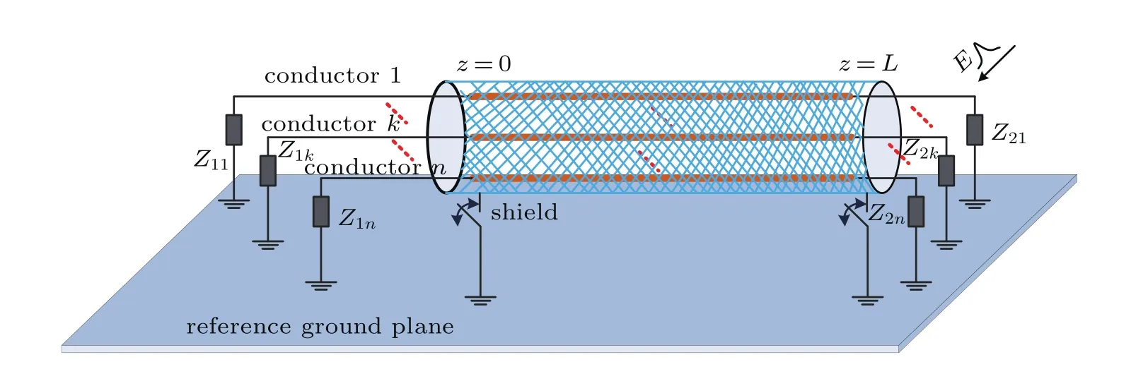
Fig.1.(color online)Illustration of the electromagnetic immunity on braid shielding mul-ticonductor cable bundles model.

Fig.2.(color online)Cross-section geometries of the complete and reduced cable bundle.
2.2.Presentation of the procedure
a)Step 1:Creation of groups of conductors based on ZS mith chart
In the first step,all the conductors of the complete cable bundle are classified as four groups with respect to the location of normalized terminal loadin Z-Smith chart,whererepresents the terminal impedance and ZCthe equivalent CM characteristic impedance of all conductors,i corresponds to the terminal number(“1”represents the near end terminal and“2”the far end terminal)and j the conductor number as illustrated in Table 1.It should be noted that the management of the cable harness grouping is just to simplify the coupling CM current calculation and the classification method will not affect the overall performance.
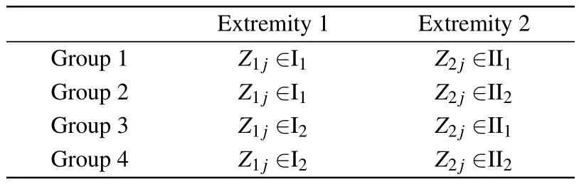
Table 1.Conductor classification table.
Figure 3 demonstrates the classification of groups of 9-conductor model.The dots in the Z-Smith chart represent near end normalized loads of each conductor,while the asterisks represent far end normalized loads.All the dots and asterisks are included in four sections denoted by I1,I2,II1,and II2.From the characteristic of Z-Smith chart,the terminal load has similar reflective properties in an adjacent area.Here,letwhereare the arbitrary terminal impedances connected to the near ends.Then we can obtain the following inequality:
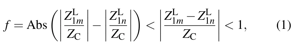
wherefis described as the distance between arbitraryandThe criterion of cable bundle grouping can be established by f.Then,we define I1as the area of f<1 with a set of a maximum number points on the graph which satisfy the condition,which means the absolute distance value of the two arbitrary normalized near end terminal loads is less than 1.Then I2the rest normalized near end loads.The II1and II2can be defined in the same manner,which means f<1 in II1and the rest in II2.Thus the 9 conductors can be sorted into 4 groups.
b)Step 2:Reduced cable bundle matrices
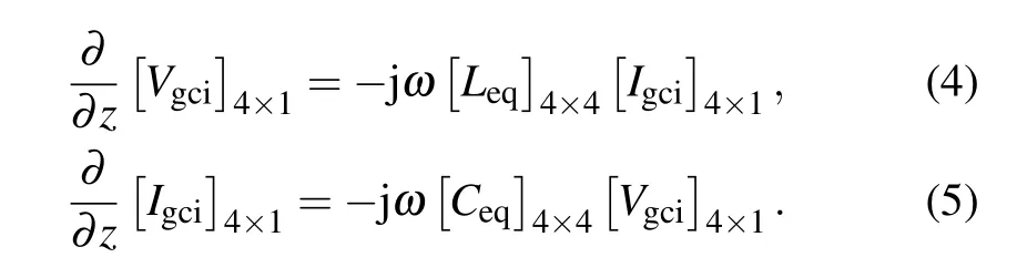
The second step aims to determine the reduced cable bundle inductance[Leq]and capacitance matrix[Ceq].According to the general MTLN theory,the equations of N-conductor cable bundle can be written as
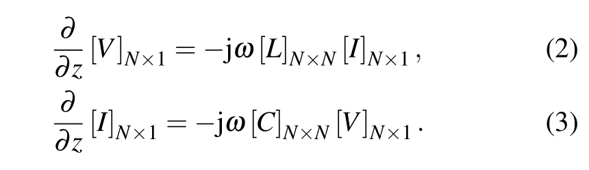
On the assumption that the same group CM current Igciequals the sum of the currents induced on each conductor of the group and all the conductors in groupihave the same group voltage Vgci,the reduced cable bundle containing four conductors is established and the equivalent MTLN equations can be modified as
From Eqs.(1)–(4),the reduced inductance matrix[Leq] and capacitance matrix[Ceq]can be obtained as follows:[23]
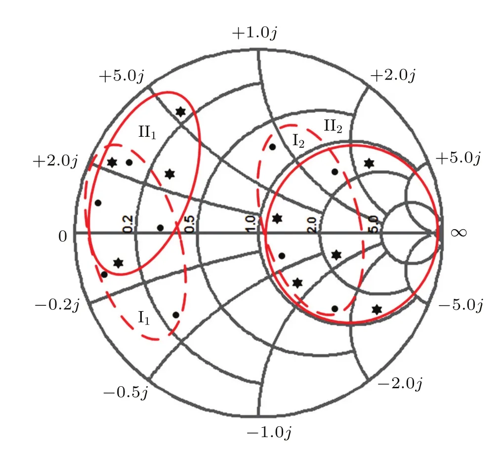
Fig.3.(color online)Criterion of cable bundle grouping based on the Z-Smith chart.
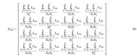

where group 1 contains conductor 1−α with the total number N1,group 2 conductor(α+1)−β with the total number N2, group 3 conductor(β+1)−ξ with the total number N3,group 4 conductor(ξ+1)−N with the total number N4.
c)Step 3:Reduced cable bundle cross-section geometry
The third step is to generate the cross-section of the reduced cable bundle,which consists of six phases.As the inductance parameters of the shielding multiconductor are associated with the structural factors,such as the distance between the analytical conductor and screen,the relative distance among conductors,the calculation of the cross-sectional geometry parameters of equivalent model are obtained thanks to study made in Ref.[24]and the knowledge of the[Leq]and [Ceq]matrices.
1)Phase 1:Estimate the central distance dibetween each equivalent conductor and the central axis of the braid shielding structure.Distance diof each equivalent conductor corresponds to the average of the distance of all the conductors of the group.
2)Phase 2:Estimate the radius riof the braid shielding structure.The analytical formula for self-inductance liiof a wire in an ideal perfectly conducting shield is equal toThus,the radius riof each equivalent conductor can be approximated by

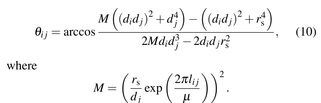
3)Phase 3:The analytical formula of mutual inductance lijbetween two conductors in an ideal perfectly conducting shield can be written as
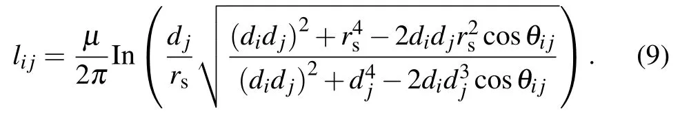
Thus,the central angle between two conductors can be approximated by
4)Phase 4:Optimize the reduced cross-section geometrical parameter di,ri,and θijbased on the dichotomic optimization and exact electrostatic calculations.
5)Phase 5:Determine the thickness of the dielectric coating surrounding each equivalent conductor while avoiding dielectric coating overlapping.
6)Phase 6:Calculate and optimize the relative permittivity εrof each wire dielectric coating,which is in accordance with the[Ceq]matrix using an electrostatic calculation.
Figure 4 shows the corresponding computational process of the proposed simplification technique used to build the cross-section geometry.Computational process for modeling the cross-section geometry of a reduced cable bundle in braid shielding structure.
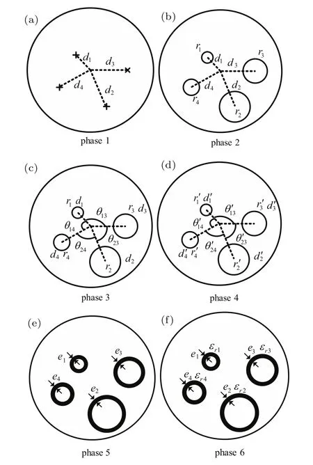
Fig.4.Computational process for modeling the cross-section geometry of a reduced cable bundle in braid shielding structure.(a)–(f)Phases 1–6.
d)Step 4:Reduced cable bundle equivalent terminal loads
The fourth and the last step consists in computing the terminal loads of the reduced model connected to each equivalent conductor end.Here,the equivalent CM loads are defined as the loads that connect conductor ends to the shield screen. The terminal load connected to an equivalent conductor end is equal to the loads at the same end of all the conductors of the group connected in parallel.
It should be noted that the previous four-step procedure is used for a simple point-to-point connected shielding cable bundle.Nevertheless,due to the calculation methods of the self and mutual inductance of shielding multiconductor,there are two important restrictions on their applicability.These are that the wires must be widely separated and the dielectric medium surrounding the wires must be homogeneous. The charge distributions around closely spaced wires will be nonuniform around their peripheries but will be approximately uniform for ratios of wire separation to wire-radius 4 and higher.
3.Validations of reduction technique by numerical models
In this section,a model of braid shielding 14-conductor is constructed to validate the proposed reduced technique with a commercial tool CST.Please note that in the following simulations the number of the same group conductors is chosen arbitrarily in order to demonstrate the universality of the presented approach to immunity prediction problems.
3.1.Complete and reduced braid shielding cable bundle description
As illustrated in Fig.2,a 14-conductor point-to-point connected cable bundle,1-meter long,located in a copper braid shielding structure with a radius of 12 mm and a thickness of 0.5 mm is modeled.Each conductor has a radius of 0.5 mm and is surrounded by dielectric coating with a thickness of 0.2 mm and dielectric constant of εr=2.5 andµr=1. The conductors with a serial number“2,3,4,5,6”are evenly distributed on the circle with a radius of 2 mm,while the conductors with a serial number“6,7,8,9,10,11,12,13,14”on the circle with a radius of 4 mm.The central coordinate of each conductor is presented in Table 2.By using modal analysis,[19]the analytical 14-conductor cable bundle characteristic impedance ZCequals 244.4 Ω.The terminal loads connected to the ends of each conductor are described in Table 3. According to the classification method proposed in the first equivalent step,the 14-conductor can be sorted into the following four groups:
1)group 1:conductors 1,2,12;
2)group 2:conductors 3,6,14;
3)group 3:conductors 4,5,7,8;
4)group 4:conductors 9,10,11,13.
The p.u.1.inductance matrix[L]and capacitance matrix [C]of the complete model in Fig.5 are
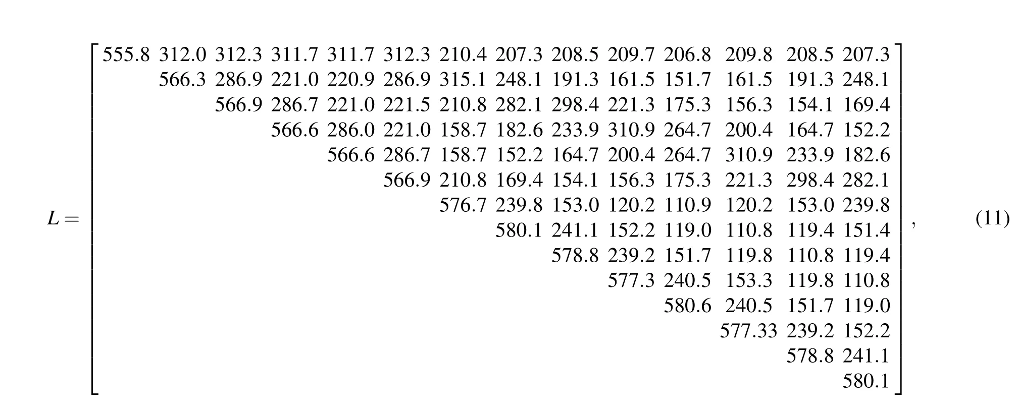
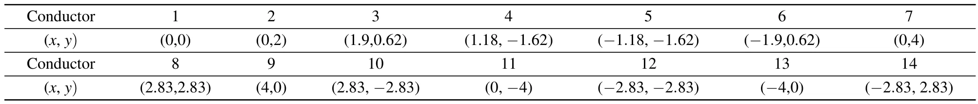
Table 2.Coordinates of each conductor of the 14-conductor shielding cable bundle(unit:mm).
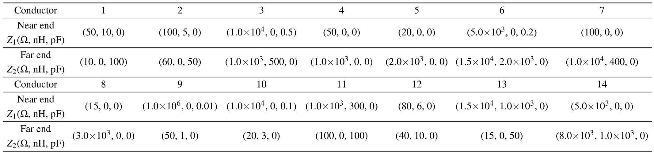
Table 3.Terminal loads of the 14-conductor shielding cable bundle.

Hereafter,inserting Eqs.(11)and(12)into Eqs.(6)and(7),the reduced p.u.1.inductance matrix[Leq]and capacitance matrix [Ceq]can be written as follows:
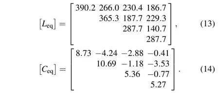
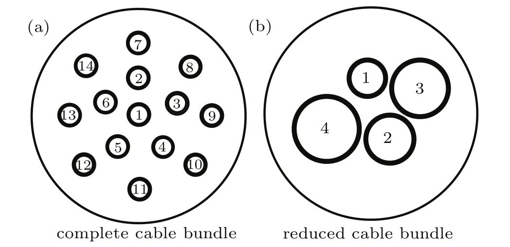
Fig.5.(a)Cross-sectional geometry of the 14-conductor complete shielding cable bundle model and(b)the corresponding 4-equivalent conductor reduced shielding cable bundle model.
After applying the six-phase procedure described in the third step in Section 2,the cross-section geometry of 4-equivalent-conductor model is obtained and illustrated in Fig.5.The equivalent CM terminal loads are calculated and the results are listed in Table 4.In addition,the relevant central distance,radius and central coordinate are listed in Table 5.
Cross-sectional geometry of the 14-conductor complete shielding cable bundle model and the corresponding 4-equivalent-conductor reduced shielding cable bundle model.
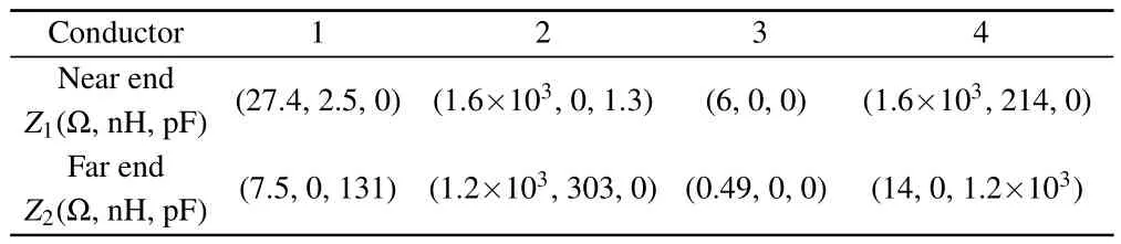
Table 4.Terminal loads of each conductor of the reduced shielding bundle.

Table 5.Central coordinate of each conductor of the reduced shielding cable bundle(unit:mm).
3.2.Comparing results
The induced CM current at the near and far ends of each cable in frequency domain are calculated by using CST Cable Studio.Based on the co-simulation technique,the adopted numerical approach uses the TLM technique to analyze the electric field around the conductors and then use AC result solver to compute the coupling to terminal loads.These computations correspond to the case of a plane wave illumination with a 1 V/m magnitude,the propagation direction 45°with respect to the reference conducting ground plane and the electric field direction parallel to the conductor.Figures 6–9 illustrate the comparison between the CM currents obtained at the ends of the complete cable bundle and the reduced cable bundle.
Using the feature selective validation(FSV)technique, it provides a way to validate computational electro magnetics(CEM)and predict the assessment of EMC data.[25,26]The FSV technique is used to evaluate the results between the complete model and the simplified model.The FSV technique shows a measure of the“quality”of the correlation between the two sets of data according to specific criteria.Among those measure indicators,we mainly focus on the total amplitude difference measure(ADMtot),the total feature difference measure(FDMtot),and the total global difference measure(GDMtot).These are available as numerical values and can be converted into a natural language descriptor on a sixlevel scale:excellent(0–0.1),very good(0.1–0.2),good(0.2–0.4),fair(0.4–0.8),poor(0.8–1.6),and very poor(>1.6).
The FSV evaluation results of Figs.6–9 are listed in Table 6.From the visual evaluation,it is obviously found that the agreement between the reduced and complete model results is still satisfactory.Thus,it is demonstrated that the proposed simplification technique can be successfully used to model the CM currents on braid shielding multiconductor cable bundles.
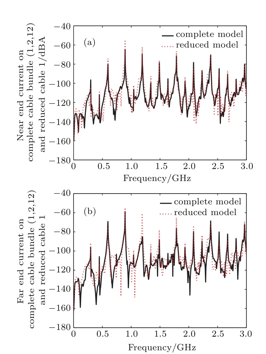
Fig.6.(color online)Comparison of the CM current in frequency domain on cable 1 between the complete(conductors 1,2,12)and reduced cable bundle model:(a)near end;(b)far end.
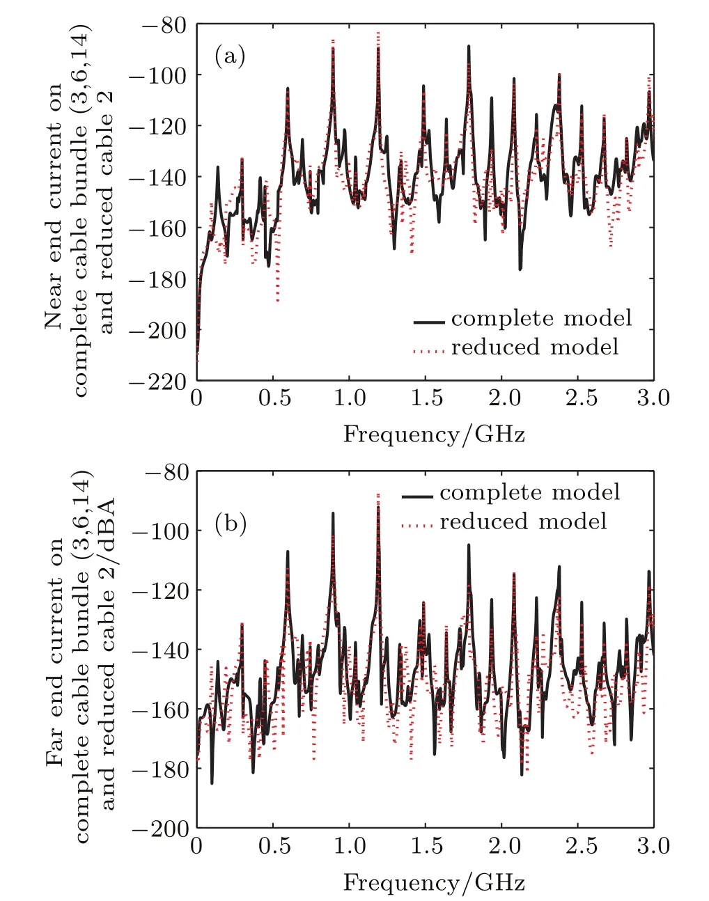
Fig.7.(color online)Comparison of the CM current in frequency domain on cable 2 between the complete(conductors 3,6,14)and reduced cable bundle model:(a)near end;(b)far end.
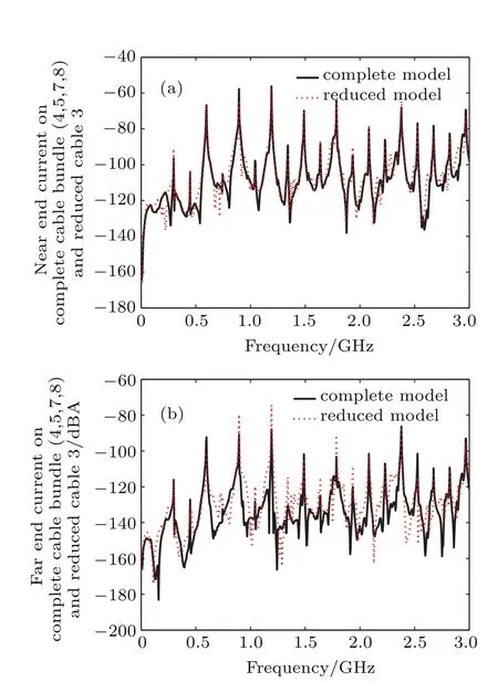
Fig.8.(color online)Comparison of the CM current in frequency domain on cable 3 between the complete(conductor4,5,7,8)and reduced cable bundle model:(a)near end;(b)far end.
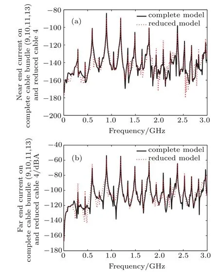
Fig.9.(color online)Comparison of the CM current in frequency domain on cable 4 between the complete(conductor 9,10,11,13)and reduced cable bundle model:(a)near end;(b)far end.
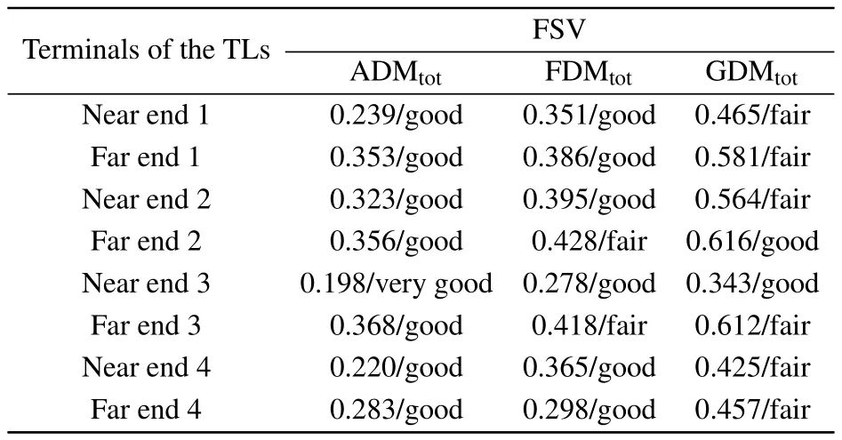
Table 6.FSV evaluation of results in Figs.6–9.
Several reasons are identified to explain the degradation of the agreement at some frequency points.In particular,we suspect the modeling of the cross-section geometry,which is determined by an approximated method.As the terminal loads involve inductance and capacitance,the impedance value is associated with frequency.In this paper,we use the mean value over frequency(0–3 GHz)of the terminal loads of the complete model to represent the equivalent loads.
3.3.Comparison of analysis time
Table 7 shows the computation times for both types of cable bundle models,calculated by CST Cable Studio.The CST simulation configuration is set to satisfy a convergence criterion and all of the computations are completed by a desktop computer with Intel(R)Xeon(R)CPUE3-1231 v3@3.40 GHz and 32 G RAM under Windows 7.From the table,it is obviously found that the reduced model behaves better in efficiency.Furthermore,it greatly simplifies the modeling process at the expense of certain calculation accuracy.
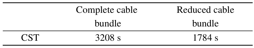
Table 7.Analysis time of the simplified and complete model.
4.Conclusions
In this paper,we propose a simplification technique to model the EM immunity problem on braid shielding multi-conductor cable bundles.In order to conveniently describe the relationship between load impedance and reflection coefficient,a new method of conductors grouping based on the knowledge of Z-Smith chart is presented.Then,a modified six-phase equivalent process is detailed.For the generation of the equivalent cross-section geometrical characteristic parameters,a central distance d and central angle θ are defined and calculated by an approximate method to determine the relative position parameters of the reduced bundle.After that,a coated 14-conductor model is proposed to validate the addressed approach by using the CST.
On the assumption that the CM current response is more critical than the differential-mode response for the EM coupling problems,our technique mainly focuses on the CM currents induced at the terminals of cable bundle.The purpose of the approach is to lower the computation time and simplify the modeling process.The simulation results confirm the possibility to model braid shielding cable bundle.From the analytical process,it can be expected that the bigger.
[1]Egot-Lemaire S,Klingler M,Lafon F,Koné L and Baranowski S 2012 IEEE Trans.Electromag.Compat.54 1222
[2]Ren D,Du P A,Nie B N,Cao Z and Liu W K 2014 Acta Phys.Sin.63 120701(in Chinese)
[3]Jiao C Q and Li Y Y 2015 Chin.Phys.B 24 104101
[4]Luo J W,Du P A,Ren D and Nie B L 2015 Acta Phys.Sin.64 010701 (in Chinese)
[5]Cao Z,Du P A,Nie B L,Ren D and Zhang Q D 2014 Acta Phys.Sin. 63 124102(in Chinese)
[6]Arianos S,Francavilla M A,Righero M and Vipiana 2014 IEEE Trans. Electromag.Compat.56 844
[7]Ridel M and Parmantier J P 2014 International Symposium on Electromagnetic Compatibility,May 12–16,2014,Tokyo,Japan,p.21
[8]Xie H Y,Li Y,Qiao H L and Wang J G 2015 Chin.Phys.B 24 060501
[9]Jobava R G,Gheonjian A L,Hippeli J and Chiqovani G 2014 IEEE Trans.Electromag.Compat.56 1420
[10]Baum C E,Liu T K and Tesche F M 1978 Interaction Note 350 467547
[11]Wu Z J,Wang L F and Liao C L 2009 Acta Phys.Sin.58 6146(in Chinese)
[12]Wan J R,Liu Y P and Zhou H L 2010 Acta Phys.Sin.59 2948(in Chinese)
[13]Sun Y X,Zhuo Q K,Jiang Q H and Li Q 2015 Acta Phys.Sin.64 44102 (in Chinese)
[14]Ferrieres X,Parmantier J P,Bertuol S and Ruddle A R 2004 IEEE Trans.Electromag.Compat.46 624
[15]Bautista M A E,Francavilla M A,Vipiana F and Vecchi G 2014 IEEE Trans.Antennas Propag.62 1523
[16]Li G,Hess G,Hoeckele R and Davidson 2015 IEEE Trans.Electromag. Compat.57 827
[17]Andrieu G,Koné L,Bocquet F and Démoulin B 2008 IEEE Trans. Electromag.Compat.50 175
[18]Andrieu G,Reineix A,Bunlon X and Parmantier J P 2009 IEEE Trans. Electromag.Compat.51 108
[19]Li Z,Shao Z J,Ding J and Niu Z Y 2011 IEEE Trans.Electromag. Compat.53 1040
[20]Li Z,Liu L L,Yan J and Xu A W 2013 IEEE Trans.Electromag.Compat.55 975
[21]Belkhelfa S,Lefouili M and Drissi K E K 2015 IEEE Trans.Magn.51 1
[22]Ridel M and Parmantier J P 2012 Proceedings ESA Workshop on Aerospace EMC,May 21–23,2012,Venice,Italy,p.1
[23]Zheng Y L 2011 Analysis of Automotive Wiring Harness Equivalent Modeland Its Application in Electromagnetic Compatibility Simulation (Ph.D.Dissertation)(Chongqing:Chongqing University)(in Chinese)
[24]Paul C R 2008 Analysis of Multiconductor Transmission Lines(New Jersey:John Wileyamp;Sons)p.196
[25]Duffy A P,Martin A J M,Orlandi A and Antonini G 2006 IEEE Trans. Electromag.Compat.48 449
[26]Orlandi A,Duffy A P,Archambeault B and Antonini G 2006 IEEE Trans.Electromag.Compat.48 460
17 February 2017;revised manuscript
31 March 2017;published online 27 July 2017)
10.1088/1674-1056/26/9/094102
∗Project supported by the National Natural Science Foundation of China(Grant No.51675086)and the National Defense Pre-Research Foundation of China (Grant No.6140758010116DZ02002).
†Corresponding author.E-mail:dupingan@uestc.edu.cn
©2017 Chinese Physical Society and IOP Publishing Ltd http://iopscience.iop.org/cpb http://cpb.iphy.ac.cn
猜你喜欢
Chinese Physics B(2022年11期)2022-11-21
广东教学报·教育综合(2022年49期)2022-04-27
连云港文学(2022年6期)2022-02-01
农机质量与监督(2020年7期)2020-12-14
北方人(2017年10期)2017-07-03
都市(2016年9期)2016-11-22
连环画报(2015年4期)2015-04-19
东南大学学报(医学版)(2015年1期)2015-03-22
中国音乐教育(2014年10期)2014-05-20
文化学刊(2014年2期)2014-01-23

- Chinese Physics B的其它文章
- Improved control for distributed parameter systems with time-dependent spatial domains utilizing mobile sensor actuator networks∗
- Geometry and thermodynamics of smeared Reissner–Nordström black holes in d-dimensional AdS spacetime
- Stochastic responses of tumor immune system with periodic treatment∗
- Invariants-based shortcuts for fast generating Greenberger-Horne-Zeilinger state among three superconducting qubits∗
- Cancelable remote quantum fingerprint templates protection scheme∗
- A high-fidelity memory scheme for quantum data buses∗