
Numerical simulation of hydraulic force on the impeller of reversible pump turbines in generating mode*
2017-09-15 13:55JinweiLi李金伟YuningZhang张宇宁KaihuaLiu刘凯华HaizhenXian冼海珍JixingYu于纪幸
水动力学研究与进展 B辑 2017年4期
Jin-wei Li (李金伟), Yu-ning Zhang (张宇宁), Kai-hua Liu (刘凯华), Hai-zhen Xian (冼海珍), Ji-xing Yu (于纪幸)
1.China Institute of Water Resources and Hydropower Research, Beijing 100048, China, E-mail: lijinw@iwhr.com
2.Key Laboratory of Condition Monitoring and Control for Power Plant Equipment, Ministry of Education, North China Electric Power University, Beijing 102206, China
3.Beijing Key Laboratory of Emission Surveillance and Control for Thermal Power Generation, School of Energy, Power and Mechanical Engineering, North China Electric Power University, Beijing 102206, China
Numerical simulation of hydraulic force on the impeller of reversible pump turbines in generating mode*
Jin-wei Li (李金伟)1, Yu-ning Zhang (张宇宁)2,3, Kai-hua Liu (刘凯华)2, Hai-zhen Xian (冼海珍)2, Ji-xing Yu (于纪幸)1
1.China Institute of Water Resources and Hydropower Research, Beijing 100048, China, E-mail: lijinw@iwhr.com
2.Key Laboratory of Condition Monitoring and Control for Power Plant Equipment, Ministry of Education, North China Electric Power University, Beijing 102206, China
3.Beijing Key Laboratory of Emission Surveillance and Control for Thermal Power Generation, School of Energy, Power and Mechanical Engineering, North China Electric Power University, Beijing 102206, China
The hydraulic force on the reversible pump turbine might cause serious problems (e.g., the abnormal stops due to large vibrations of the machine), affecting the safe operations of the pumped energy storage power plants. In the present paper, the hydraulic force on the impeller of a model reversible pump turbine is quantitatively investigated through numerical simulations. It is found that both the amplitude of the force and its dominant components strongly depend on the operating conditions (e.g., the turbine mode, the runaway mode and the turbine brake mode) and the guide vane openings. For example, the axial force parallel with the shaft is prominent in the turbine mode while the force perpendicular to the shaft is the dominant near the runaway and the turbine brake modes. The physical origins of the hydraulic force are further revealed by the analysis of the fluid states inside the impeller.
Pump turbine, hydraulic force, numerical simulation, generating mode, vortex, backflow
Introduction
The pumped energy storage power plant involves an important large-scale energy storage technology, which can enhance the stability of the electric grid and relieve the fluctuations of the output power caused by the renewable energies[1,2](e.g., the wind[3], solar and tidal[4]energies). In the pumped energy storage power plant, the reversible pump turbine (RPT) is generally adopted due to its high efficiency, flexibility and economical benefits. For recent reviews of the reversible pump turbine, readers are referred to Zhang et al.[5,6]. One of the complexities of the reversible pump turbine technologies is its frequent starts and stops, switching between different working states (e.g., theload rejection or increment, the switches between the pumping mode and the generating mode) to meet the demand of the electric grid, leading to the generations of the vortex in the turbines[5]. Zhang et al.[6]clearly defined the various kinds of the aforementioned working conditions of the reversible pump turbines.
Currently, the reversible pump turbines are being challenged by unstable flow-induced phenomenon. Zhang et al.[7]experimentally investigated the large pressure fluctuation in the prototype RPT. We found that the pressure fluctuation of the RPT could be categorized into three regions based on the load conditions and characteristics of the fluctuation. Such kind of operations could lead to serious problems for the turbine components (e.g., the mechanical fatigue of the impeller) due to the large pressure fluctuations and vibrations[8-10].
Among the forces on the reversible pump turbine systems, there are three kinds of excitation forces according to their physical origins[8]: the hydraulic forces, the mechanical forces and the electromagnetic forces. The present paper focuses on the hydraulicforces. As compared with the conventional hydraulic turbines (e.g., the Francis turbine[11]), the reversible pump turbine has many unique features (e.g., fewer blades and higher rotating speed), as well as different operating parameters (e.g., the high water head), leading to a much larger hydraulic forces generated within the reversible pump turbines. Hence, in most cases, there exist prominent hydraulic forces on the fluid passing components of the reversible pump turbine (especially the impeller).
The abnormal hydraulic force affects the safe operations of the pumped energy storage power plant seriously. The hydraulic force on the impeller can be decomposed into two components: the axial force (parallel with the shaft) and the force perpendicular to the shaft. The axial force could lead to the force unbalance of the turbine (e.g., the lift of the turbine), leading to the damage of the unit (e.g., the bearings and the labyrinth ring) and abnormal stops of the reversible pump turbine. And, the force perpendicular to the shaft leads to the swing of the shaft. For example, in the Tianhuangping power station of China, the frequent lifts of the rotational components of the reversible pump turbines were observed during the load increment from 200 MW to 300 MW in the generating mode, leading to the abrasive damage of the machine and hence unplanned closing down of the machine. The primary on-site study shows that the lift of the machinery is caused by the large hydraulic force on the impeller during the above transition process. In our previous experimental work[7,10], a detailed experimental study was performed based on the on-site measurements of the vibration, the pressure fluctuation and the swing of the shaft. It is desirable to shed light on the physical origins of the hydraulic force on the impeller of the reversible pump turbine.
One of the difficulties of studying the hydraulic force on the impeller of a pump turbine is the presence of a great number of influential factors on these issues (e.g., the working states, the guide vane openings and the turbine geometries). For example, in the generating mode, the pump turbine could pass three working zones: the turbine zone, the turbine brake zone and the reverse pump zone, which are separated by the runaway line and the zero-flow-rate line[6]. A recent review of the reversible pump turbine can be found in Zhang et al.[6]. Hence, it is not possible and economical to experimentally determine those forces on the whole impeller in the above working states. Instead, the numerical simulation is a good choice to fulfill this task. In the literature, a great number of simulations were carried out[12-19], relating to the reversible pump turbines, mainly focusing on two aspects: the understanding of the S-shaped performance curve and the eliminating method (e.g., the misaligned guide vanes[13]and the hydraulic design of the impeller[14,15]), and the large pressure fluctuation[16,17]. The definition of the S-shaped performance curve of the reversible pump turbine was given in Zhang et al.[6]. The existence of the S-shaped performance characteristic curve could significantly affect the safe operation of the reversible pump turbine (in terms of the rotational speed)[18,19]. The engineering background of those studies is the instability under the idle load conditions, leading to large oscillations of the rotational speed and causing difficulties to the synchronous process with the electric grid. The literature review shows that the hydraulic force on the impeller of the reversible pump turbine remains an issue to be explored.
1. Numerical methods
This section gives a detailed introduction of the numerical simulation and related setups, together with the simulated operating conditions of the model reversible pump turbine. Figure 1 shows the main components of the reversible pump turbine (e.g., the spiral casing, the stay vanes, the guide vanes, the impeller and the draft tube) marked with different colors. Figure 2 shows the details of the impeller (including the crown, the blades and the band).

Fig.1 (Color online) The basic geometry of the investigated reversible pump turbine. The main components are marked with different colors in the figure: The stay vanes and the spiral casing (in purple color), the guide vanes (in orange color), the impeller (in red color), and the draft tube (in blue color)
The mesh convergence test is performed to ensure the validities of the present simulation. For the modelling of the rotor-stator interactions (e.g., the impeller-vanes interactions, here), the movement of the impeller is implemented through settings of the domain as a moving component.
The simulated cases are selected based on the model test of the performance curve for three guide vane openings (6o,21oand 24o, respectively). For each guide vane opening, several typical cases are simulated in order to cover the possible operating conditions. A summary of the simulated cases is shown in Table 1 with the corresponding category of their operating conditions. In Table 1, the discharge factor (Q11) is defined as
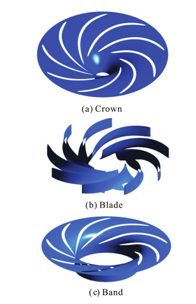
Fig.2 (Color online) A detailed view of the impeller. The top, middle and bottom subplots are the crown, the blades and the band, respectively

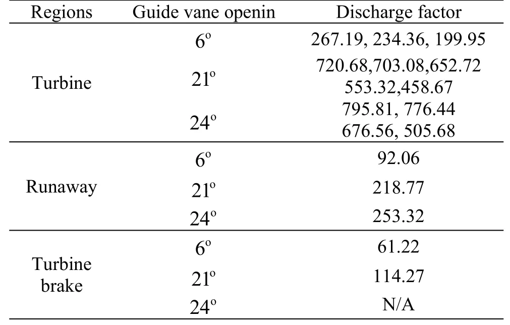
Table 1 A list of operational conditions for numerical simulations and related operating regions
whereQLis the volumetric discharge,Dis the nominal diameter of the impeller, andHis the water head. In our simulations, a single phase model is adopted and the flow-induced multiphase flow[20-22]are ignored. In some cases, the bubbly flow could be prominent with significant influences on the wave propagation[23]and resonances[24]through interactions[25,26].
2. Analysis of hydraulic force on the impeller
In this section, a detailed analysis of the hydraulic force on the impeller of the reversible pump turbine working is carried out under different operating conditions (including the turbine mode, the runaway mode, and the turbine brake mode) for different guide vane openings. In the present paper, our attention is mainly focused on the generation of the hydraulic force on the impeller because these forces are strongly related to many current challenges of the reversible pump turbine design and the on-site problems (e.g., the vibrations and the swing of the shaft).
In the following sections, the force on the components of the reversible pump turbines are calculated based on the simulation results using the post-processing functions. In the present paper, only the hydraulic force generated by the fluids inside the reversible pump turbines is considered. Due to the high pressure inside the reversible pump turbine, the magnitude of the viscous force is quite limited. The employed post-processing functions could give the statistics of the force in three-dimensions (X,Y,Zdirections, respectively), which are further processed to obtain the whole force on the impeller. For a further analysis, the total forces are decomposed into two components: that parallel with the shaft (denoted byand that perpendicular to the shaft (denoted by

Fig.3 (Color online) The variations of the total force on the impeller versus the discharge factor for guide vane openings 6o, 21oand 24o
Figure 3 shows the variations of the amplitude of the total force on the whole impeller of the reversible pump turbine versus the discharge factor for different guide vane openings (6o,21oand 24o, respectively). In Fig.3, the marked arrows indicate the runaway modes. It is found that the total force under the same operating conditions varies greatly with the guide vane openings. Along the guide vane opening lines, with the decrease of the discharge, the total force firstly decreases due to the limited amount of the fluid passing the impeller. With the further decrease of the discharge (especially near the runaway), a dramatic increase of the total force is observed. Such kind of increases of the forces on the impeller is mainly induced by the abnormal fluid flow inside the bladechannels. In the turbine brake mode, the total force on the impeller still remains of a high value, indicating that the fluid patterns under these operating conditions are complex. The details of the analysis of the fluid states are in Section 3.

Fig.4 (Color online) The variation of the amplitude ofFxyandFzof the impeller versus the discharge factor for guide vane opening 6o
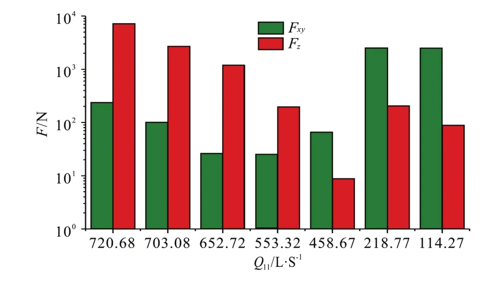
Fig.5 (Color online) The variation of the amplitude ofFxyandFzof the impeller versus the discharge factor for guide vane opening 21o
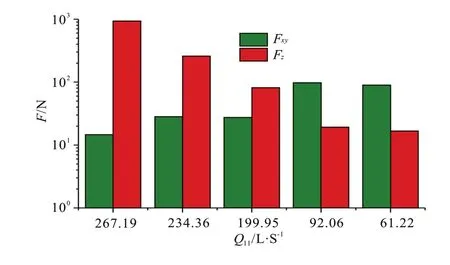
Fig.6 (Color online) The variation of the amplitude ofFxyandFzof the impeller versus discharge factor for guide vane openings 24o
Figures 4-6 show the variations ofFxyandFzversus the discharge factor for different guide vane openings (6o,21oand 24o, respectively). In the turbine mode, the total force is mainly dominated by theFz. In this region, the amplitudes ofFzare about ten times of those ofFxy. However, near the runaway (e.g., in the turbine brake mode), the axial forceFzis quite negligible whileFxyis the dominant component. Noticing that the diameter of the present model reversible pump turbine is only 0.24 m, the amplitude of the force near the runaway is quite significant, possibly leading to the swing of the shaft. This finding agrees well with our previous on-site measurements. In Li et al.[10], the shaft displacements in different directions of upper, lower and turbine guide bearings were measured. The results show that in the runaway mode, the displacements of all those bearings are the largest among all tested operating conditions (referring to Fig.3 of Ref.[10]). The significant values ofFxymay also be due to the oscillations of the rotational speed during the idle load mode.

Fig.7 (Color online) The variation of axial force contributed by the crown, the band and the blades versus discharge factor for guide vane openingo6
In order to further reveal the physical mechanisms of those hydraulic forces, the contributions of three main components of the impeller (i.e., the crown, the band and the nine blades) to the axial forces are also shown in Figs.7-9 for the guide vane openings 6o, 21oand 24o, respectively. The crown and the band make great contributions to the axial force while the contributions of the blades can be safely neglected because when the fluid passes the blades, the forces generated on each blade finally cancel each other due to the symmetric smooth flow. For small guide vane openings (e.g., 6o), the variations of the contribution of the crown and the band to the axial force are rather limited while for large guide vane openings (e.g., 21o, 24o), they decrease clearly with the decrease of the discharge factor.

Fig.8 (Color online) The variation of axial force contributed by the crown, the band and the blades versus discharge factor for guide vane openingo21
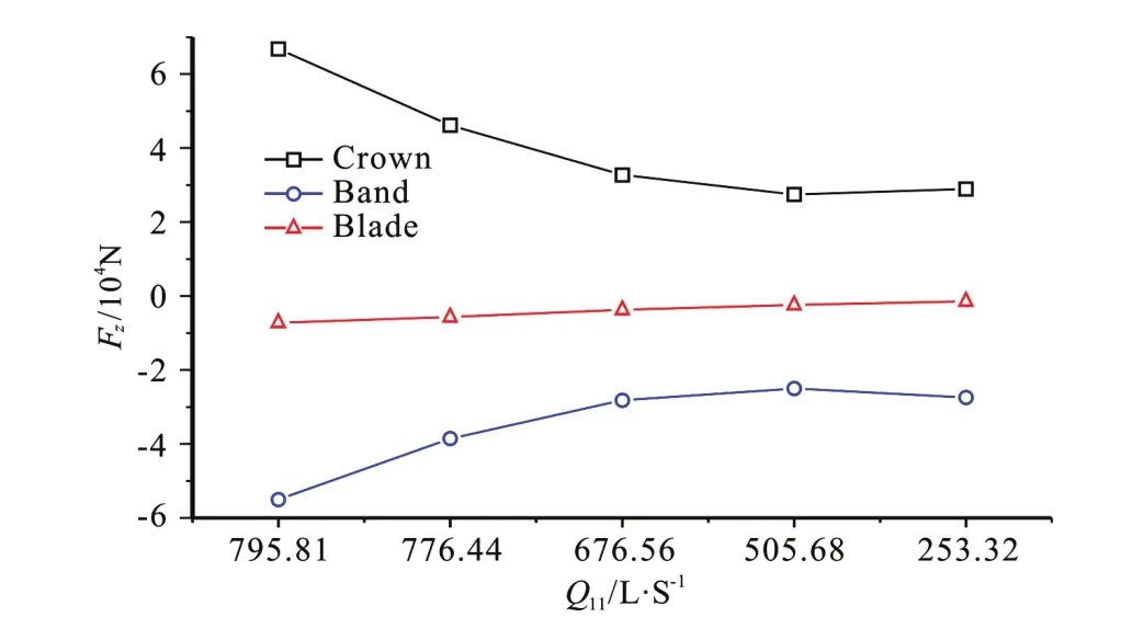
Fig.9 (Color online) The variation of axial force contributed by the crown, the band and the blades versus discharge factor for guide vane opening 24o

Fig.10 (Color online) The variation of amplitude ofFxycontributed by the crown, the band and the blades versus discharge factor for guide vane openingo6
Figures 10-12 show the contributions of three main components of the impeller (i.e., the crown, the band and the blades) toFxyfor the guide vane openings 6o, 21oand 24o, respectively. Near the runaway mode, the blades make the most significant contribution to theFxyfor all the guide vane openings.

Fig.11 (Color online) The variation of amplitude ofFxycontributed by the crown, the band and the blades versus discharge factor for guide vane opening 21o
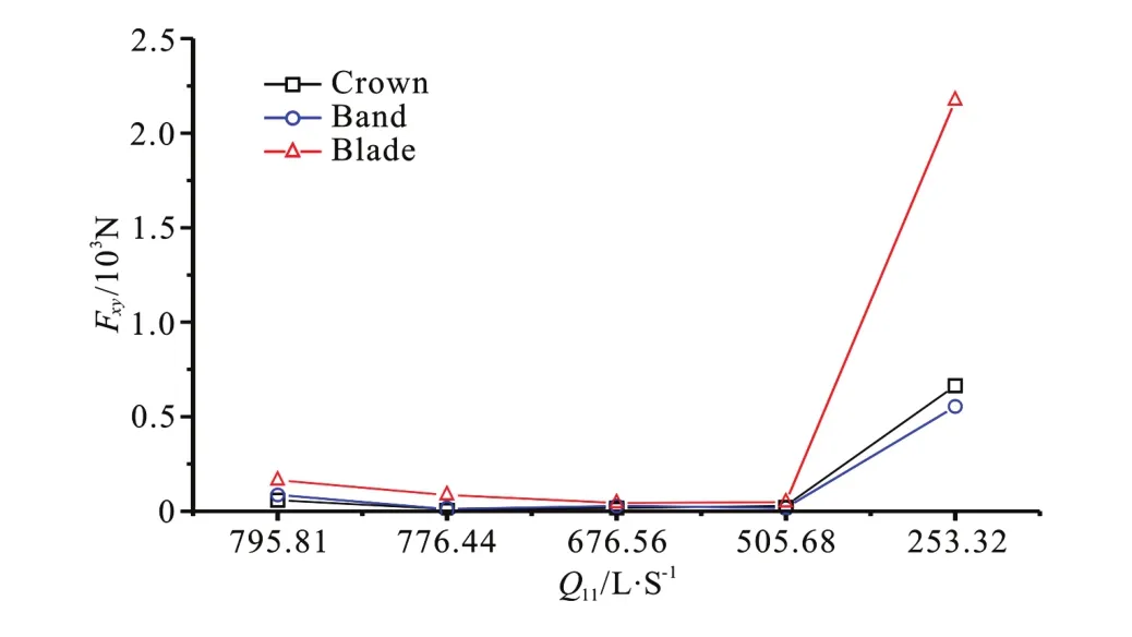
Fig.12 (Color online) The variation of amplitude ofFxycontributed by the crown, the band and the blades versus discharge factor for guide vane opening 24o
Therefore, it can be concluded that the significant values ofFxyare due to the asymmetric flow in the impeller channels caused by the fluid distortions (e.g., the swirling flow).
A brief discussion of the zero-flow-rate mode and the reverse pump mode is given as follows. In the zero-flow-rate mode, the force is extremely small due to the rather limited amount of the fluid passing through the turbine. In the reverse pump mode (with the change of the flow directions), the axial force is the dominant component and varies slightly with the flow rate. In the engineering practice, the operation of the reversible pump turbine is carefully controlled to avoid entering (possibly) this mode.
3. Analysis of the fluid states
As shown in Section 2, the hydraulic force on the impeller is greatly affected by the fluid states. In this section, a comparison of the fluid states (in terms of the vortex and the backflow) between the turbine mode, the runaway mode and the turbine brake mode under different operating conditions is made for theguide vane openingo21.
In the vortex analysis, a widely adoptedQ-criterion is employed. In order to compare the vortices in the impeller under different working conditions, a dimensionless value ofQ(e.g., denoted asQ0, which is normalized by using the maximum value ofQin each computational case) is adopted. For comparisons, we set the dimensionlessQ0=0.1 in all cases. Figure 13 shows the comparisons of the vortex structures in the impeller of the reversible pump turbine under different working conditions. In the turbine mode (Fig.13(c)), a limited number of vortices are distributed homogeneously in the blade channels and at the outlet of the impeller. Under this working condition, the generation of the vortex is uniform in the circumferential direction but not prominent (e.g., in terms of the amount of the vortex). Hence, as shown in Figs.4-6, no prominentFxyforce is observed in the turbine mode because the vortices are uniformly distributed in the impeller. With the decrease of the discharge (entering the runaway and turbine brake modes as shown in Figs.13(b) and 13(a)), the vortex structures become non-uniform, leading to the blockage of the channel. As a result,Fxyforce in the runaway and turbine brake modes are of great amplitudes (as shown in Figs.4-6).

Fig.13 (Color online) Vortex identification based onQ-criterion in the impeller of the reversible pump turbine under different working conditions.Q0=0.1
The existence of the backflow (e.g., the flow in the direction from the impeller to the guide vanes) in the turbine brake mode and the runaway mode is another reason for the observed large amplitude ofFxyforce. Figure 14 shows the backflow at the inlet of the impeller with the streamlines inside the impeller (colored by the magnitude of velocity). As shown in Fig.14(c), no backflow is observed in the turbine mode. However, very significant backflows are observed in the runaway and turbine brake modes (as shown in Figs.14(b) and 14(a)), leading to a further distortion of the fluid flow inside the impeller. Hence, under those conditions, the backflow further aggravates the non-uniformity of the fluid flow inside the impeller, leading to significant unbalanced forces (e.g., the large amplitude ofFxyforces in the turbine brake and runaway modes).

Fig.14 (Color online) States of backflow at the inlet of impeller and streamlines in the impeller of the reversible pump turbine under different working conditions
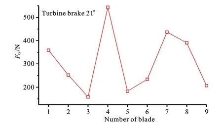
Fig.15 (Color online) The variation of the amplitude ofFxycontributed by different number of blades versus discharge factor in turbine brake mode for guide vane openingo21
To further quantify the asymmetric flow in different blade channels, Fig.15 further shows the variations of the amplitude of forceFxyon each blade (with the total blade number of 9). The variations of the force are obviously observed with the maximum force of about 550 N on the blade No. 4 while the minimum force of only about 150 N on the blade No. 3. In the turbine mode for the same guide vane opening, the variations of the force on different blades could be safely neglected due to the symmetricflow inside the impeller.
4. Conclusions
In the present paper, the numerical simulations of the fluid flow inside the model reversible pump turbine are performed with a focus on the analysis of the generation of the hydraulic force on the impeller.
(1) The dominant force component depends strongly on the working conditions. In the turbine mode, the axial component (mainly contributed by the crown and the band) parallel with the shaft is the dominant one. In the runaway and turbine brake modes, the component perpendicular to the shaft caused by the asymmetric flow inside impeller is the dominant one.
(2) The physical reason of the large amplitude of the force component (perpendicular to the shaft) is the existence of the backflow and the vortex, which aggravate the non-uniformity of the flow inside the impeller.
(3) The above features of the hydraulic force generated by the distorted flow should be paid a great attention for the prevention of the impeller fatigue due to the frequent shifts between working conditions.
[1] Jiang R., Wang J., Guan Y. Robust unit commitment with wind power and pumped storage [J].IEEE Transactions
[2] Caralis G., Papantonis D., Zervos A. The role of pumpedon Hydro Power Systems, 2012, 27(2): 800-810. storage systems towards the large scale wind integration in the Greek power supply system [J].Renewable and Sustainable Energy Reviews, 2012, 16(5): 2558-2565.
[3] Zhang Y., Tang N., Niu Y. et al. Wind energy rejection in China: Current status, reasons and perspectives [J].Renewable and Sustainable Energy Reviews, 2016, 66(12): 322-344.
[4] Huang B., Shi J., Wei X. Model testing of a series of counter-rotating type horizontal-axis tidal turbines with 500 mm diameter [J].ASME Journal of Engineering for Gas Turbines and Power, 2017, 139(10): 102602.
[5] Zhang Y., Liu K., Xian H. et al. A review of methods for vortex identification in hydroturbines [J].Renewable and Sustainable Energy Reviews, 2017, doi:http//dx.doi.org/10.1016/j.rser.2017.05.058.
[6] Zhang Y., Zhang Y., Wu Y. A review of rotating stall in reversible pump turbine [J].Proceedings of the Institution of Mechanical Engineers, Part C: Journal of Mechanical Engineering Science, 2017, 231(7): 1181-1204.
[7] Zhang Y., Chen T., Li J. et al. Experimental study of load variations on pressure fluctuations in a prototype reversible pump turbine [J].Journal of Fluids Engineering, 2017, 139(7): 074501.
[8] Egusquiza E., Valero C., Valentin D. et al. Condition
[9] Egusquiza E., Valero C., Huang X. et al. Failure investimonitoring of pump-turbines. New challenges [J].Measurement, 2015, 67: 151-163.
[10] Li J., Hu Q., Yu J. et al. Study on S-shaped characteristic gation of a large pump-turbine impeller [J].Engineering Failure Analysis, 2012, 23: 27-34. of Francis reversible unit by on-site test and CFD 2013, 56(9): 2163-2169.
[11] Chen T., Zhang Y., Li S. Instability of large-scale prototype Francis turbines of Three Gorges power station at part load [J].Proceedings of the Institution of Mechanical Engineers, Part A: Journal of Power and Energy, 2016, 230 (7): 619-632. simulation [J].Science China Technological Sciences,
[12] Wang L., Yin J., Jiao L. et al. Numerical investigation on the “S” characteristics of a reduced pump turbine model [J].Science China Technological Sciences, 2011, 54(5):
[13] Sun H., Xiao R., Liu W. et al. Analysis of S characteristics 1259-1266. and pressure pulsations in a pump-turbine with misaligned guide vanes [J].Journal of Fluids Engineering, 2013, 135(5): 051101.
[14] Yin J. L., Wang D. Z., Wei X. Z. et al. Hydraulic improvement to eliminate S-shaped curve in pump turbine [J].
[15] Yang W., Xiao R. Multiobjective optimization design of aJournal of Fluids Engineering, 2013, 135(7): 071105. pump-turbine impeller based on an inverse design using a combination optimization strategy [J].Journal of Fluids Engineering, 2014, 136(1): 014501.
[16] Guo L., Liu J., Wang L. et al. Pressure fluctuation propagation of a pump turbine at pump mode under low head
[17] Liu J., Liu S., Sun Y. et al. Three dimensional flow simucondition [J].Science China Technological Sciences, 2014, 57(4): 811-818.
[18] Olimstad G., Nielsen T., Børresen B. Stability limits of relation of load rejection of a prototype pump-turbine [J].Engineering with Computers, 2013, 29(4): 417-426. versible-pump turbines in turbine mode of operation and measurements of unstable characteristics [J].Journal of Fluids Engineering, 2012, 134(11): 111202.
[19] Olimstad G., Nielsen T., Børresen B. Dependency on impeller geometry for reversible-pump turbine characteristics in turbine mode of operation [J].Journal of Fluids Engineering, 2012, 134(12): 121102.
[20] Zhang Y., Zhang Y., Qian Z. et al. A review of microscopic interactions between cavitation bubbles and particles in silt-laden flow [J].Renewable and Sustainable Energy Reviews, 2016, 56(4): 303-318.
[21] Zhang Y., Zhang Y. Chaotic oscillations of gas bubbles under dual-frequency acoustic excitation [J].Ultrasonics Sonochemistry, 2017, doi: http://dx.doi.org/10.1016/j.ultsonch.2017.03.058.
[22] Zhang Y. N., Li S. Improved formulas for thermal behadynamics, 2016, 28(2): 325-328.
[23] Zhang Y., Guo Z., Gao Y. et al. Acoustic wave propagation in bubbly flow with gas, vapor or their mixtures [J].Ultrasonics Sonochemistry, 2017, doi: http://dx.doi.org/10.1016/j.ultsonch.2017.03.048.
[24] Zhang Y., Zhang Y., Li S. Combination and simultaneous resonances of gas bubbles oscillating in liquids under dual-frequency acoustic excitation [J].Ultrasonics Sonochemistry, 2017, 35(3): 431-439.
[25] Zhang Y., Zhang Y., Li S. The secondary Bjerknes force between two gas bubbles under dual-frequency acoustic excitation[J].Ultrasonics Sonochemistry, 2016, 29(3): 129-145.
[26] Zhang Y. N., Min Q., Zhang Y. N. et al. Effects of liquid compressibility on bubble-bubble interactions between vior of oscillating nanobubbles [J].Journal of Hydrooscillating bubbles [J].Journal of Hydrodynamics, 2016, 28(5): 832-839.
(Received February 27, 2016, Revised July 17, 2016)
* Project supported by the National Natural Science Foundation of China (Project No. 51506051).
Biography:Jin-wei Li (1981-), Male, Ph. D., Senior Engineer
Yu-ning Zhang,
E-mail: y.zhang@ncepu.edu.cn

- 水动力学研究与进展 B辑的其它文章
- Spatial relationship between energy dissipation and vortex tubes in channel flow*
- Numerical analysis of flow separation zone in a confluent meander bend channel*
- Mechanics of granular column collapse in fluid at varying slope angles*
- Numerical simulation of submarine landslide tsunamis using particle based methods*
- Double-averaging analysis of turbulent kinetic energy fluxes and budget based on large-eddy simulation*
- Prediction of the future flood severity in plain river network region based on numerical model: A case study*