
U-model Enhanced Dynamic Control of a Heavy Oil Pyrolysis/Cracking Furnace
2018-05-02 07:11QuanminZhuDongyaZhaoShuzhanZhangandPriteshNarayan
Quanmin Zhu,Dongya Zhao,,Shuzhan Zhang,and Pritesh Narayan
I.INTRODUCTION
THE introduction consists of five sub-sections:a review of existing representative approaches in modelling of oil cracking furnaces,a review of control approaches to such furnace operations,a brief overview of U-model based control system design and,with reference to the critical survey/analysis,justifying the necessity of the study and listing the major contributions of the current work,and finally summarising the remaining sections of the study.
A.Modelling of Heavy Oil Cracking Furnace
Cracking feedstock,heated and conveyed into the furnace tube of the radiant section of a furnace,absorbs heat from the external radiation chamber,causing heating and cracking.In order to obtain satisfactory quality and quantity of product,it is necessary to build up reference models to describe the reaction in the tube,and the heat transfer dynamic process both inside and outside the tube.This involves many variables for controlled operation,such as length of material temperature,pressure distribution and product distribution.It has been noted[1]that smoke flow from the radiation interior is subject to intense turbulence,and furnace temperature distribution varies with burner positioning and actual combustion conditions.In regard to modelling,zero dimensional models cannot properly reflect temperature distribution inside the furnace hearth,and high dimensional models of flue gas temperature distribution inside the furnace inevitably lead to complexity in analysis and computation(particularly for online control).Therefore,choice of the model for heat transfer in radiation chamber must compromise between accuracy and complexity.
A brief summary of existing modelling work is given here.Representatively there have been heat transfer models in tube furnace[2],one dimensional temperature models for gradient furnace[3],two dimensional models[4],and high dimensional models[5].
For model analysis and simulation,there has been examination of pure radiation heat transfer in the cylindrical tubular heater[6],studies on radial temperature distribution of the furnace tube[7],and simulation of radiation section of cracking furnaces[8].Even though these models cover dynamics,they have seldom considered nonlinear effects existing in the process.
B.Control of Heavy Oil Cracking Furnace
The advanced control and optimisation of ethylene production processes has seen much theoretical/analytical development and application[9].For example,optimization and advanced control of thermal cracking processes[10],operation optimisation of naphtha cracking furnaces[11],[12],closedloop steady-state real-time optimisation(CSRTO systems)implemented by the Mobil Chemical Company of the State of Texas[13],which demonstrated application of computer control to the Mobil ethylene plant.
The most successful method of advanced process control technology used in the process of ethylene production has been the dynamic model control(DMC)method[14],represented by the Plus DMC of the Aspen Tech Company.In 1997 it was reported that Plus DMC accounted for 70 percent of world-wide ethylene plant advanced process control(APC).Plus DMC mainly consists of estimating,linear programming,and dynamic control modules[15].The Setpoint Company[16]has developed a computer optimization control system for an olefin plant,which has been used for stable control,constrained control,local optimization control,and overall optimization control of four-level hierarchical control strategy,which has achieved good results.Additionally,ABB Simcom Company has developed an olefin plant simulation and optimization software package OPSO(Ole fins plant simulation and optimization),which has been successfully used in many ethylene plants[17].
It has been observed that the most control strategies used so far have been PID(proportion,integral and derivative)or PID type controllers,and nonlinear process control is still an area to be explored.Generally applicable controller designs may therefore be developed,exploiting even faster and more flexible computation resources.
C.U-model Enhanced Control System Design
Since the proposition of U-model(in terms of“providing concise and applicable control oriented model structure for designing complex nonlinear control systems”)in the first author’s Ph.D.thesis[17],a series of the corresponding U-model enhanced control design approaches have been developed[18].It has been claimed that the U-model based control system design methodology radically reduces complexity in classical control system design and plant model based design.The role of the plant model is effectively reduced to that of a reference for converting to the U-model domain and determining the next-step controller output by resolving one of the U-model roots[19].U-model based control is based on the hypothesis that it is possible to use linear methodologies to directly provide solutions for control of a large class of smooth nonlinear dynamic plant models,and thus,by principle of parsimony,simplify and generalise nonlinear system control design.The whole framework for U-model based control system design is shown in Fig.1.
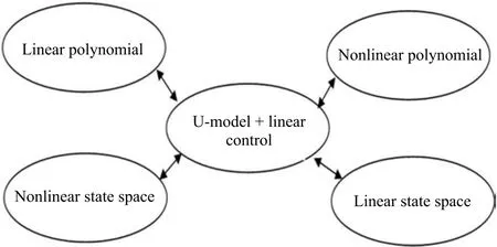
Fig.1. U-model based control system design framework.
The U-model systematically transforms smooth(polynomial)nonlinear models into a class of plant input/controller outputubased polynomials,thus resolving plant dynamic inversion,by finding one of the roots of the U-model.The advantage of the control oriented model transform is to simplify controller design procedures in line with those for linear control system design.It should be mentioned that under such a transform there is nothing lost from original nonlinear models.Regarding U-model based control research development,[19]established the foundation framework,with pole placement control of NARMAX(Nonlinear auto regressive moving average with exogenous input)models.More recently,U-model enhanced control system design has been expanded to U-general predictive control(UGPC)[20]and U-sliding mode control(USMC)[18].For nonlinear state space models,a U-backstepping framework is under development to iteratively step backward to determine control output in resolving multi loop U-models.In brief,U-model covers a wide range of nonlinear plants,which may be used as a basis for applying linear control techniques.This should be considered with another potential research topic:expanded alternative U-models for neural networks,network control modes,multiagents,etc.This may permit reducing the complexity of the current model structures of some newly developed representative control system design approaches[14],[21],[22].It should be noted that U-model based approaches maintain the same control performance as other approaches,but make their design procedure more feasible,concise,and general,without unnecessary design repetition on plant model changes.Even for linear plant models,U-model approaches have the same merits over their classical counterparts.
D.Justification and Contribution of the Study
The study mainly considers establishing a systematic procedure in designing nonlinear dynamic control systems for nonlinear dynamics in actual existing chemical engineering processes which are seldom considered in modelling and control due to difficulty and lack of generality in analysis,design,and computation.The design procedure includes:1)modelling,from a principle model,and formulation of a control oriented model to U-model;2)control system design coping with nonlinearities and a conditional stable dynamic process;and 3)a bench test example.It should be noted that the control system design approach developed in the study is fundamentally different from a Jacobian linearization for small range operation,which is the basis for almost all other linear control system design approaches.Furthermore,this is the first study of issues associated with control of conditionally stable nonlinear process within the U-model framework,which has not theoretically proved the controller,but heuristically formulated and numerically demonstrated with the bench test example.
E.Section Organisation of the Study
The rest of the paper is organised into the following sections.In Section II,a nonlinear dynamic model is built up for heavy oil pyrolysis/cracking furnace,which is the basis for the process temperature control.In Section III,the U-model is introduced and the associated properties are presented to provide a proper description of the model structure and characteristics.Its relation to Hammerstein,Wiener,and NARMAX models are explained to show the generality and applicability in control system design.Subsequently,remarks with examples are presented for explanation and understanding of the conversion from classical polynomials to the U-model set.A general U-model based controller design procedure is explained with three different types of examples.In Section IV,The U-model based temperature control of the heavy oil cracking furnace is designed in terms of pole placement and stabilisation.In Section V,a series of computational experiments are conducted to numerically demonstrate the theoretically developed results.In Section VI,a brief conclusion is drawn to summarise the results and to explain some potential research issues.
II.MODELLING OF HEAVY OIL CRACKING FURNACE
It must be acknowledged at the outset that the modelling description and re-organisation are largely resourced from a Ph.D.thesis[23]to enable formatting of a proper control oriented nonlinear dynamic model.
In common with many chemical engineering processes,proper temperature control is a requirement for the quality and quantity of chemical products.The pyrolysis process for heavy oil is very much dependent on the temperature in the furnace and the outer wall of the tube.The steady-state model of the pyrolysis process,linking the temperature of the outer wall of the tube/output to the temperature in the furnace/input,is the basis of expansion into the corresponding dynamic model for temperature control.In general,the steady-state model of a cracking furnace includes three balance principles,material balance(cracking reactions in chemical kinetics models),heat balance and momentum balance.Similar to finite element analysis,Kumar molecular dynamics model structure[24]can be used to describe the input and output relationships in terms of dynamics and steady states on a small section of the furnace,and thus the furnace characteristics can be extrapolated.
With reference to the detailed modelling work[23],the dynamic variation of furnace wall temperature can be determined by the following differential equation
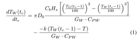
where for a particular model representing high temperature range of a cracking furnace.
tcis the continuous time.
TWis the temperature of the outer wall of the tube(the flue gas through radiation and convection to the outer wall of the furnace tube)and defined as the model output.
TGis the temperature in furnace and defined as the model input or control variable to regulate the temperature of the outer wall of the tube.
CbHs=5.67W/(m2·K3),the product,is absolute black body radiation constant.
D0=0.135m is external diameter of reaction tube.
Tis the average temperature of pyrolysis gas,the average temperature of pyrolysis gas is 1109K(the high temperature range of cracking furnace:973K-1173K).
kis the total heat transfer coefficient 6.463W/(m2·K3)
GW=69kg/m is quality of unit length furnace tube(the quality range of high temperature section of cracking furnace:67.2-69.9kg/m).
CPWis the specific heat capacity of furnace tube material 822.6J/(kg·K)(the specific heat capacity range in high temperature of cracking furnace:758.35-873.56J/(kg·K)).
Remark 1:Equation(1)is also called as input and output dynamic model.In regard to its structure,it is a nonlinear continuous time model.
To facilitate digital controller design and implementation by computer or digital control instruments,discretise the continuous time model(1)into a discrete time model by a difference operator as
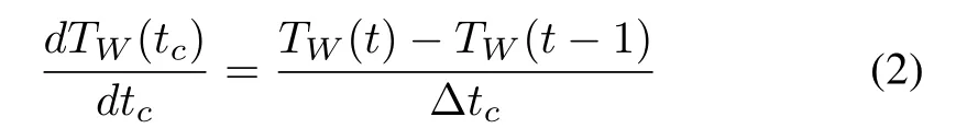
wheret=1,2,...is the sampling instance and Δtcis the sampling interval.Accordingly,the discrete time model is determined with
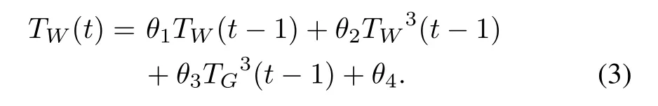
With reference to the given furnace model parameters above and setting the sampling interval Δtc=100,it gives the parameter vector in(3)

A.U-model Based Control Systems Design
This section presents the definition and foundation of the U-model,explains its representation of Hammerstein models,Wiener models,and NAMARX(non-linear autoregressive moving average with exogenous input)models,which have been widely used in process industries.With this control oriented model,it outlines the generic controller design procedure with a few of examples of pole placement control,general predictive control,and a newly proposed stabilisation control.
B.Definition of U-model
Consider a general smooth nonlinear discrete time dynamic process

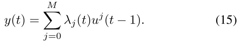
wherey(t)∈R andu(t-1)∈R are the output and input(also known as controller output in control system design)signals of the process respectively at discrete time instantt(1,2,...),nis the process order,andf(·)is a smooth linear or non-linear function.Then,the process can be represented with a U-model structure which is de fined below as a controller outputu(t-1)oriented polynomial[15],

whereMis the degree of model input(controller output)u(t-1),the time varying parameter vectorλ(t)=[λ0(t)...λM(t)]∈RM+1is a function of past inputs and outputs(u(t-2),...,u(t-n),y(t-1),...,y(t-n)),and the other non-(u(t-1)terms/parameters.
Property 1:Letφ:RL+1→RM+1be the map from polynomial model(6)to U-model(7)and its inverse beφ-1,that isf(pi,θi)→f(uj,λj).Then,it has the following properties[15]:
1)the map is injective(one to one);
2)the map is surjective(onto);
3)therefore,the map is bijective as it is both injective and surjective;
4)the map is invertible;
5)the map does not change any both models characteristics,such as output response,stability,dynamics and statics.
Remark 2:In consideration of the U-model(7),a control oriented prototype,there is no change of properties compared with various classical polynomial models in representation of(6)such as dynamics,stability,and input and output external relationship.Therefore,in model properties,U-model and classical polynomial models are equivalent.In the model expression,U-model is time varying in parameters(by reorganisation of classical model structure)and convenient for control systems design.In another point of view,U-model bridges nonlinear problems with linear solutions.
C.Representations of U-model to the Other Classical Model Sets
It has been studied that the U-model has solid base to cover various existing nonlinear polynomial models as its subsets.Therefore,those developed U-model based design procedures should be applicable to the model sets and their variations.
Examples of popular and widely recognised model sets are described here,to show the U-model potential coverage of application.
1)Hammerstein models:
The basic Hammerstein model is a cascade structure of the nonlinear static(memoryless)block and the linear dynamic block which can be described by the following formulas[25]

wherey(t)andu(t-1)are the output and input signals of the process respectively at discrete time instantt(1,2,...),XH(t)is the output signal of the nonlinear static block,andfH(.)is a non-linear function of inputu(t-1).
The corresponding equivalent U-model can be expressed as
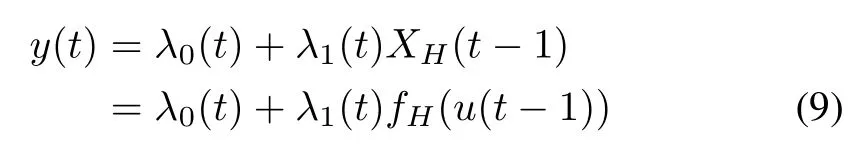
where
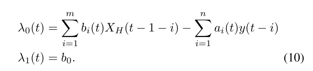
Remark 3:Hammerstein models can be used to describe many different processes,especially if their main nonlinear behaviour is induced by actuators such as valves,an essential component for controlling of fl uid in flow and pressure in many chemical engineering applications[26].It has been observed[27]that this model structure has been successfully applied to chemical processes such as heat exchange,distillation,and biological processes.
2)Wiener models:
The basic Wiener model is a cascade structure of the linear dynamic block and the nonlinear static block which can be described by the following formulas[28].

wherey(t)andu(t-1)are the output and input signals of the process respectively at discrete time instantt(1,2,...),XW(t)is the output signal of the linear dynamics,andfH(.)is a non-linear function ofXW(t).
The corresponding equivalent U-model can be expressed as
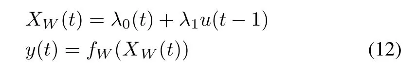
where

Remark 4:Wiener models have been used to describe the control of pH neutralisation processes[29]and solid oxide fuel cell systems[30].
3)NARMAX models:
The general NARMAX polynomial model[31]can be expressed as
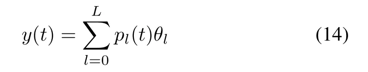
where the regression termspl(t)are the products of past inputs and outputs such asu(t-1)y(t-3),u(t-1)u(t-2),y2(t-1),andθlare the associated parameters.
The corresponding equivalent U-model can be expressed as
An example[18],from polynomial model to the U-model conversion,is shown below.
The polynomial model is
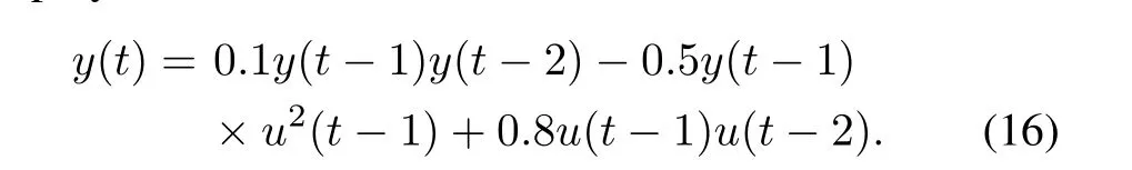
And the U-model can be determined in notation of(17)

whereλ0(t)=0.1y(t-1)y(t-2),λ1(t)=0.8u(t-2),andλ1(t)=0.8u(t-2).
Remark 5:NARMAX models can be used to represent wide range of smooth nonlinear dynamic systems and are considered as good approximation to hard nonlinear dynamic systems as well[32].It should be noted that even NARMAX models have been well studied in the domain of system identification,they have almost not been systematically studied in control system design due to the model structure not being a class of control oriented prototype.
D.U-model Enhanced Controller Design
Assumption 1:The general process of(6)is assumed to be open loop stable and minimum phase(otherwise,need stabilisation means before design).Accordingly,signals within the designed closed loop are bounded.
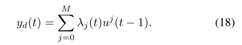
In order to use linear polynomial mode based design approaches,de fine the desired process output asyd(t),which is specified either by designers or customers in advance.Accordingly,the relationship between a specified process outputyd(t)and the requested corresponding controller outputu(t-1)can be expressed in terms of U-model
This prototype establishes a framework for proposing a twostep design procedure.
Step 1(design desired output yd(t)):The first task of the design is to determine the desired process outputyd(t)according to a specified performance index,here three typical examples are listed for reference:
1)Pole placement control(PPC)[19]has been designed in terms of
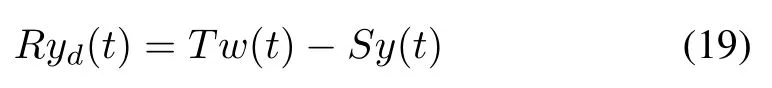
wherey(t),yd(t)andw(t)are the process output,desired/designed process output,and reference input respectively.The polynomialsR,S,andTare used to specify the desired process outputyd(t).
General predictive control(GPC)[20]has been designed in terms of

whereY,Yd(t)andW(t)are the vectors ofy(t),yd(t)andw(t)respectively.Q1andQ2are the corresponding weighting coefficient matrices.
It should be noted that the first design step for both controllers above do not require process model,which means once design off can be applicable to many different process models.
2)Stabiliser(newly presented in the study)

It should be noted that the design of critical nonlinearity cancellation and linear compensation can be separately achieved.Once again the design of linear compensation above does not require process model.
Step 2(work out controller output u(t-1)):Then,the remaining design task is to resolve one of the roots of(18)to obtain the controller outputu(t-1).That is

where Ψ [∗]is a root-solving algorithm,such as Newton-Raphson algorithm.A detailed analysis on the root solving issues has been presented[19].As the second stage is a process model dependent process,each time a plant model changes,its corresponding U-model needs to be re-structured.
Remark 6:Regarding feasibility of the controller implementation and computational efficiency,as the controller is a once off design,it can be flexibly implemented with dedicated hardware.While a process model may change,(i.e.,U-model change),additional implementation merely entails re-setting of the root solver.Thus,from hardware and software implementation,U-model based control systems are more economic,effective,and efficient.In computation,resolving inversion of the plant model is much simpler and quicker than resolving inversion of some format of the controller model and process model together.This is particularly critical in situations with limited power resources,such as control of unmanned aerial vehicles(UAV).
III.CONTROL SYSTEM DESIGN OF HEAVY OIL CRACKING FURNACE
A typical cracking furnace control system is shown in Fig.2.There are three variables contributing to the temperature variation on the outer wall of the reaction tube:1)the boiler feed water temperature;2)the steam drum temperature;and 3)the fuel gas burn generated temperature through radiation and convection to the outer wall of the tube.In this study,the third is selected to be variable as the temperature control,defined as in(1),the other two assumed to be constants.In control system structure,the three variable controlled and tailored single variable controlled closed loop block diagrams are shown in Fig.3 is the three variable controlled system is the single variable controlled system.
For convenience,the notations in the original furnace wall model(3)are changed to use conventional notations in control system design

wherey(t)=TW(t),u(t)=TG(t-1).
Accordingly,the corresponding U-model(23)can be expressed by

whereλ0(t)=θ1y(t-1)+θ2y3(t-1)+θ4,λ3(t)=θ3.
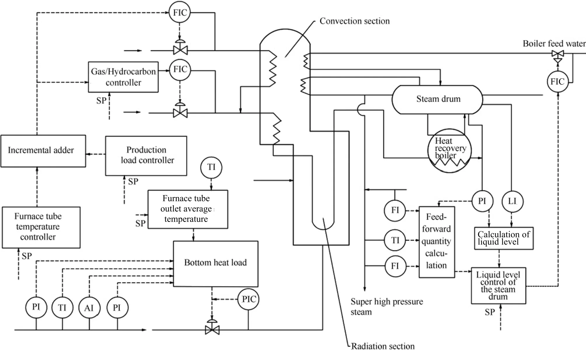
Fig.2. Cracking furnace control system.
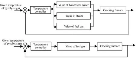
Fig.3. Control system block diagrams.
A.Design of U-model Based Pole Placement Controller(UPPC)
The main feature of the pole placement control is to assign the closed loop nonlinear control system as behaving like a linear system with specified poles and steady errors.Here the U-PPC design procedure is specified for designing the control of the temperature on the outer wall of the reaction tube in the heavy oil pyrolysis/cracking furnace.
The controller structure in this study,as described with(19),is specified with

where the three polynomials are specified to achieve,1)the closed loop poles to be a complex conjugate pair-0.6603±j0.2463,which corresponds to a natural frequency of 1rad/s and a damping ratio of 0.7,2)zero steady state error to step input.It should be noted that,in contrast to classical design approaches,U-model based design procedure does not require process model(no matter linear or nonlinear)in the first stage.
Consequently,for the closed loop characteristic equation,it gives

whereqis the forward operator.
To achieve the zero steady state error to a step input,it gives

For the polynomialsRandS,specify
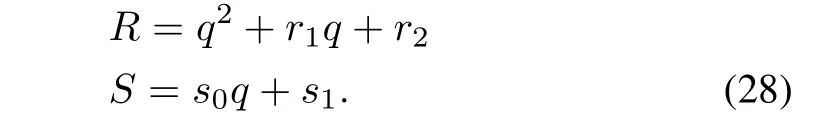
Substituting the specification of(28)into Diophantine to
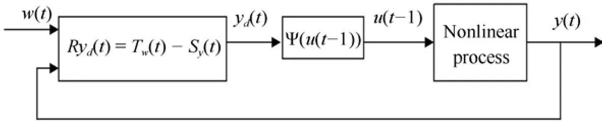
Fig.4. U-model based pole placement control system.
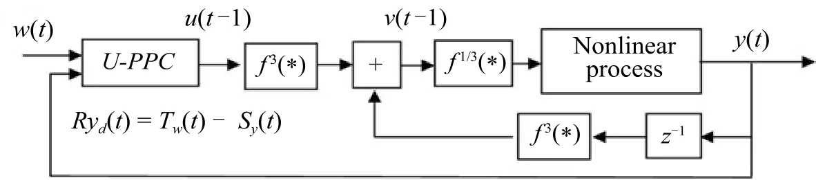
Fig.5. U-model based stabilisation control system.
formulate the coefficients in polynomialsRandS[19]with

To guarantee the computation convergence of the sequenceyd(t),that is to keep the difference equation with a stable dynamics,letr1=-0.9,r2=0.009.This assignment corresponds to the characteristic equation ofyd(t)as(q-0.89)×(q-0.01)=0.Then,the coefficients in polynomial s can be determined from the Diophantine equation[19]

Substituting the coefficients of the polynomialsRandSinto controller of(25),gives rise to

Therefore,the controller outputu(t-1)can be determined from resolving(7)by lettingy(t)=yd(t).
The completed control system structure is shown in Fig.4.
B.Design of U-model Based Stabilising Controller(U-SC)
It should be noted that the precondition for designing a pole placement controller is that the process is stable at least within the operational region.If a process,frequently subjects to nonlinear dynamics,is not globally stable or unstable in certain range of operation set points,a stabilising controller should be considered.Accordingly,the main feature of the stabilising control is to stabilise the process in closed loop while it works in an unstable operation interval.The stabilisation controller is designed by the following procedure.
The controller structure in this study,as described with(21),is specified by:
Linear compensation part uses the designed U-PPC nonlinear cancellation is designed to remove the critical nonlinear dynamic termy3(t-1).The complete control system structure is shown in Fig.5.
Remark 7:It should be noted that,in general,the control design objective in such situations should not be perfect tracking or asymptotically tracking,instead it should be satisfied with,for example,bounded-error tracking,small tracking error being achieved for desired trajectories of particular interest[33].
IV.COMPUTATIONAL EXPERIMENTS—BENCH TESTS
This nonlinear process model of(3)is conditional open loop stable,which is dependent on process input amplitude.A number of computational experiments have been conducted with a set of different amplitude step input stimulations to find the model output responses as:
Stable-monotonic response(almost as a first order linear model)to a step input|u(t)|≺13.
Stable-decayed oscillatory to a step input 13≺|u(t)|≺16.
Constant oscillation to a step input|u(t)|=16.
Unstable-monotonic response to a step input|u(t)|≻16.
Regarding testing of the designed control system performance,both U-PPC and U-SC are specified for controlling the temperature on the outer wall of the reaction tube in the heavy oil pyrolysis/cracking furnace,at different amplitude level of operation reference inputs.
A.Bench Test of U-PPC
Assign the step reference input with amplitude between 0-5,which means the process is working within an open loop stable operation range.
The output response of the designed control systems with assigned poles and steady state properties is shown in Fig.6 and the pole placement controller output is shown in Fig.7.On inspection of the plots,it can be noted that:1)For reference temperatures,with the U-model control,the furnace temperature has been effectively regulated to follow the operational point change with the designed transient and steady state response.The decayed oscillatory response,relatively rich dynamic characteristics,was only for simulation tests,and the monotonic response can be similarly designed with the U-model approach;2)There is a very short duration of abnormal fluctuation,within the control range,at the initial stage,which may be induced by root solver initial adaptation and/or nonlinear dynamic effect.Accordingly,the controller output gives a large reaction to suppress the unwanted fluctuation.Afterwards,the furnace temperature response follows the operation reference well;3)Once again this experiment con firms that the pole placement controller is one-off designed and applicable to many different plant models,the sole difference between the applications is their U-model structure and associated parameters.If classical approaches are used,on plant changes the entire controller must be redesigned due to the dependence of the plant model in the design.
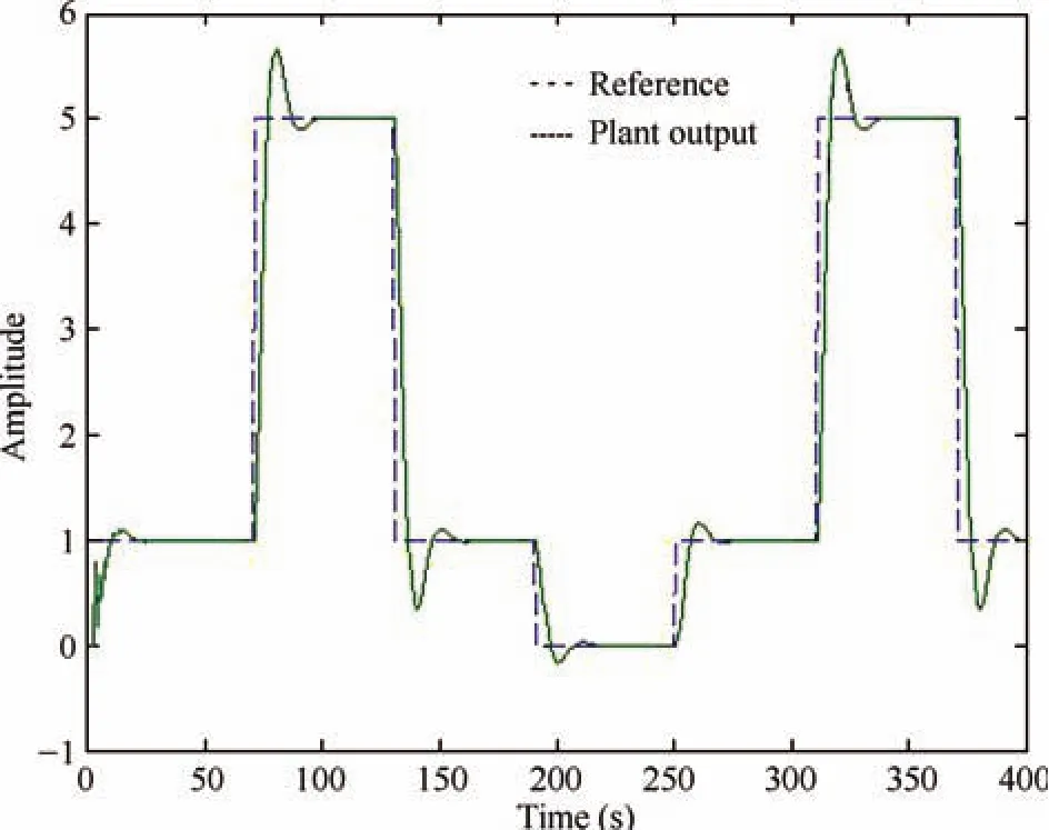
Fig.6. U-model based stabilisation control system.
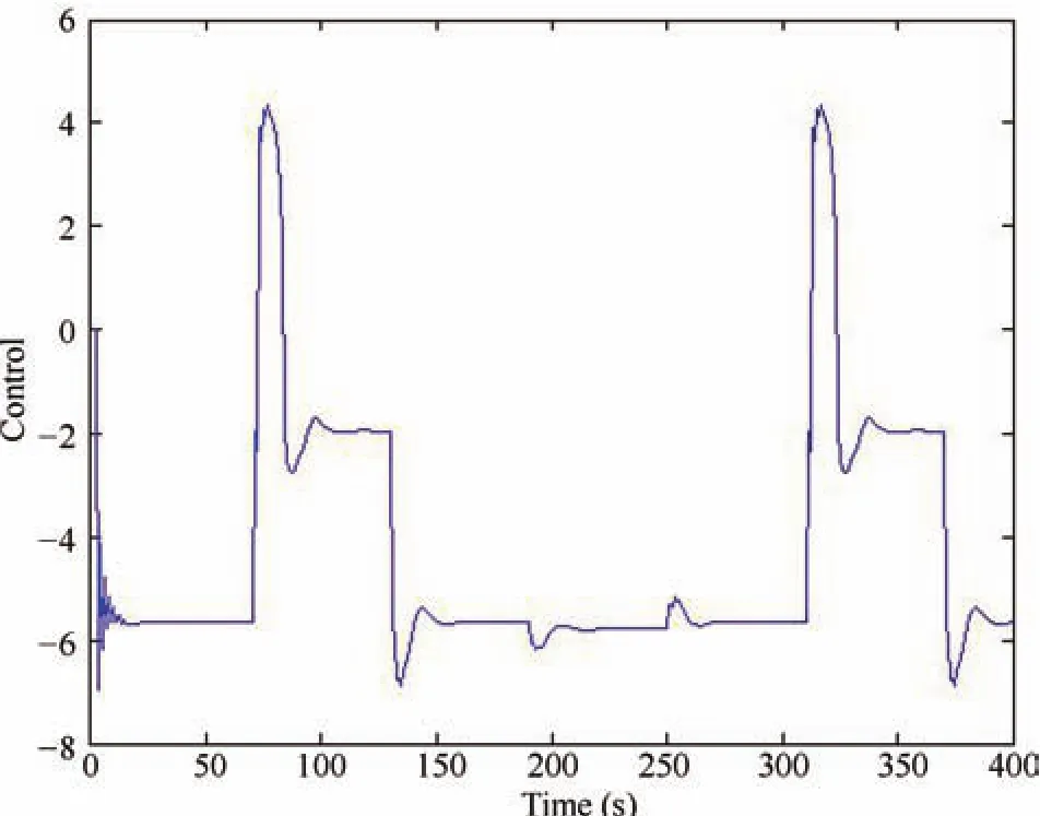
Fig.7. U-model based stabilisation control system.
B.Bench Test of U-SC
Assign the step reference input with amplitude between 0-30,which means that the process is working within an open loop unstable operation range.
The output response of the designed control systems with the specified error response is shown in Fig.8 and the controller output is shown in Fig.9.From inspection of the plots,the similar observation as that from Figs.8 and 9 can be concluded.Additionally:1)The initial transient response is better,because the nonlinear term in the plant has been cancelled by feedback stabilisation;2)Feedback stabilisation successfully stabilises the unstable open loop process with U-model control in closed loop,with a new function added in U-control toolbox;3)controller output is reasonably good,and a large amplitude is not needed to effectively react to operational temperature variations.
V.CONCLUSION
Once again this study has demonstrated the following hypothesis and research methodology claimed within the U-model framework.
1)It is possible to use linear methodologies to directly provide solutions for control of a large class of smooth nonlinear dynamic process models,and therefore to simplify and generalise nonlinear control system design by the principle of parsimony.With a critical distinction from classical approaches,U-model based design is independent of the plant/process model.2)A three step research methodology:a)convert a nonlinear model into a linear approach applicable structure;b)identify the induced problems from the model conversion;c)revise the linear approach to accommodate the identi fied problems in the model conversion.

Fig.8. U-model based stabilisation control system.
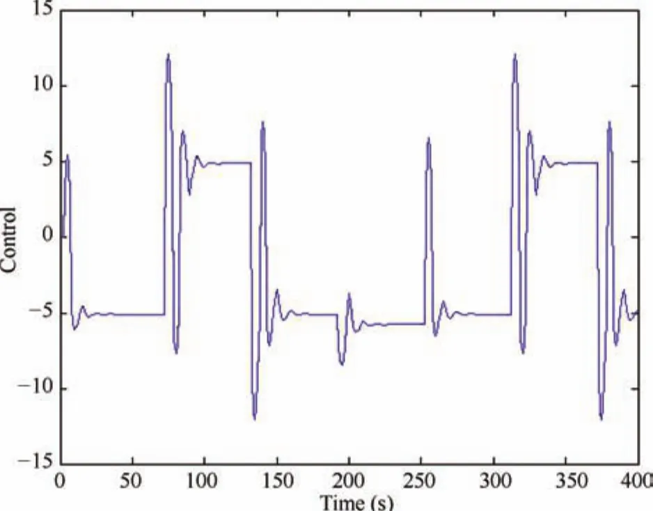
Fig.9. U-model based stabilisation control system.
Another attempt in the study is using U-model framework to design a stabilisation controller for the conditionally unstable nonlinear dynamic process.The next step will be laboratoryscale bench tests with real rigs,which may include model uncertainty,time delay,and other typical challenging issues frequently encountered in many process industries.
Last,but not least,it should be pointed out that the methodology and algorithms with U-model based control system design are relatively new and little investigated,with no leading journal publications.Counter examples and comments on the weakness of the new approach are welcome,in order to strengthen its theoretical understanding and applicability in process industries.
[1]H.Y.Shao,G.Y.Miao,and Z.Q.Zhang,“State feedback control design for a networked control model of systems with two additive time-varying delays,”Int.J.Innovat.Comput.Inform.Control,vol.11,no.4,pp.1457-1469,2015.
[2]R.Hasan,N.Perera,S.Baddage,and M.Persson,“Numerical modelling of heat transfer in a tube furnace for steel wire annealing,”inProc.29th Int.Manufacturing Conf.(IMC29),Northern Ireland,2012.
[3]S.C.Guo, “Tube type furnace heat transfer mathematical model,”J.Chem.Eng.,vol.3,pp.255-263,1981.
[4]R.M.V.Rainara,P.M.Fleliers,and G.F.Froment,“The coupled simulation of heat transfer and reaction in a pyrolysis furnace,”Chem.Eng.Sci.,vol.43,no.6,pp.1223-1229,1988.
[5]T.A.Cheema,H.Ali,and C.W.Park,“Thermal-FSI based analysis of annealing process for a steel wire in a tube furnace,”Appl.Therm.Eng.,vol.98,pp.340-351,Apr.2016.
[6]G.J.Yang,Z.Q.Huang,and X.P.Yang,“Experimental and pure radiative heat transfer model of a cylindrical tubular heater,”J.Petrol.Proc.,vol.5,nol.3,pp.47-54,1989.
[7]G.J.Heynderickx,G.G.Cornelis,and G.F.Froment,“Circumferential tube skin temperature pro files in thermal cracking coils,”AIChE J,vol.38,no.12,pp.1905-1912,Dec.1992.
[8]P.M.Plehiers,G.C.Reyniers,and G.F.Froment,“Simulation of the run length of an ethane cracking furnace,”Ind.Eng.Chem.Res.,vol.29,no.4,pp.636-641,Apr.1990.
[9]P.Li,Q.A.Li,R.X.Lei,A.J.Chen,L.L.Ren,and W.Cao,“Development and application of advanced process control system for ethylene cracking heaters,”CIESC Journal,vol.62,no.8,pp.2216-2220,2011.
[10]A.Savu,G.Lazea,and P.S.Agachi,Optimization and advanced control for thermal cracking processes,”inProc.20th European Symp.Computer Aided Process Eng.CESCAPE20,pp.20-25,2010.
[11]W.Huang, “Improve naphtha cracker operation,”Hydrocarbon Proc.,no.2,pp.79-83,Feb.1980.
[12]K.J.Yu,X.Wang,and Z.L.Wang,“Self-adaptive multi-objective teaching-learning-based optimization and its application in ethylene cracking furnace operation optimization,”Chemometr.Intell.Lab.Syst.,vol.146,pp.198-210,Aug.2015.
[13]A.Georgiou,A.V.Sapre,P.Taylor,R.E.Galloway,and L.K.Casey,“Ethylene optimization system reaps operations and maintenance bene fits,”Oil Gas J.,vol.96,no.10,pp.46-50,Mar.1998.
[14]H.Y.Shi,C.L.Su,J.T.Cao,P.Li,J.P.Liang,and G.C.Zhong,“Nonlinear adaptive predictive functional control based on the Takagi-Sugeno model for average cracking outlet temperature of the Ethylene Cracking Furnace,”Ind.Eng.Chem.Res.,vol.54,no.6,pp.1849-1860,Feb.2015.
[15]P.Li,Q.A.Li,R.X.Lei,A.J.Chen,L.L.Ren,and W.Cao,“Development and application of advanced process control system for ethylene cracking heaters,”CIESC Journal,vol.62,no.8,pp.2216-2220,2011.
[16]H.L.Xing,X.Z.Zhong,and J.Li,“Linear extended state observer based back-stepping control for uncertain SISO nonlinear systems,”Int.J.Innovat.Comput.Inform.Control,vol.11,no.4,pp.1411-1419,Jul.2015.
[17]Q.M.Zhu, “Identification and control of nonlinear systems,”Ph.D.dissertation,University of Warwick,UK,1989.
[18]P.Shi,F.B.Li,L.G.Wu,and C.C.Lim,“Neural network-based passive filtering for delayed neutral-type semi-Markovian jump systems,”IEEE Trans.Neural Netw.Learn.Syst.,vol.28,no.9,pp.2101-2114,Sep.2017.
[19]Setpoint Inc., “Plant optimization(Ole fins),”Hydrocarbon Proc.,vol.69,no.9,pp.90-120,1990.
[20]Q.M.Zhu,D.Y.Zhao,and J.H.Zhang,“A general U-Block modelbased design procedure for nonlinear polynomial control systems,”Int.J.Syst.Sci.,vol.47,no.14,pp.3465-3475,Sep.2016.
[21]Q.M.Zhu and L.Z.Guo,“A pole placement controller for non-linear dynamic plants,”Proc.Inst.Mech.Eng.Part I:J.Syst.Control Eng.,vol.216,no.6,pp.467-476,Sep.2002.
[22]W.X.Du,X.L.Wu,and Q.M.Zhu,“Direct design of a U-Model-based generalized predictive controller for a class of non-linear(polynomial)dynamic plants,”Proc.Inst.Mech.Enger,Part I:J.Syst.Control Eng.,vol.226,no.1,pp.27-42,Sep.2012.
[23]Y.F.Hu, “Study on modeling of naphtha pyrolysis furnace,”Ph.D.dissertation,Tsinghua University,China,2005.
[24]P.Kumar and D.Kunzru,“Modeling of naphtha pyrolysis,”Ind.Eng.Chem.Process Des.Dev.,vol.24,no.3,pp.774-782,Jul.1985.
[25]Z.Babik and P.Dosta´l,“Hammerstein and Wiener Models in nonlinear control of servo-speed mechanism AMIRA DR300,”Adv.Res.Sci.Areas,vol.1,no.1,pp.1727-1733,Dec.2012.
[26]H.T.Zhang,H.X.Li,and G.R.Chen,“Dual-mode predictive control algorithm for constrained hammerstein systems,”Int.J.Control,vol.81,no.10,pp.1609-1625,Aug.2008.
[27]T.H.Lee,J.H.Park,S.M.Lee,and S.C.Lee,“Nonlinear model predictive control for solid oxide fuel cell system based on Wiener model,”World Acad.Sci.Eng.Technol.,vol.48,no.50,pp.820-825,2010.
[28]S.Mahmoodia,J.Poshtana,M.R.Jahed-Motlaghb,and A.Montazeria,“Nonlinear model predictive control of a pH neutralization process based on Wiener-Laguerre model,”Chem.Eng.J.,vol.146,no.3,pp.328-337,Feb.2009.
[29]S.A.Billings,Nonlinear System Identification:NARMAX Methods in the Time,Frequency,and Spatio-Temporal Domains.Chichester,West Sussex:Wiley,John and Sons,2013.
[30]J.J.E.Slotine and W.P.Li,Applied Nonlinear Control.New Jersey:Prentice Hall,1991.
[31]A.Q.Huang and Y.Wang,“The Hammerstein predict model of control valve based on least square support vector machine,”Appl.Mech.Mater.,vol.472,pp.164-170,Jan.2014.
[32]S.Zheng,X.Y.Zhang,C.B.Qi,and H.C.Zhou,“Modeling of heat transfer and pyrolysis reactions in ethylene cracking furnace based on 3-D combustion monitoring,”Int.J.Therm.Sci.,vol.94,pp.28-36,Aug.2015.
[33]Q.M.Zhu,Y.J.Wang,D.Y.Zhao,S.Y.Li,and S.A.Billings,“Review of rational(total)nonlinear dynamic system modelling,identification,and control,”Int.J.Syst.Sci.,vol.46,no.12,pp.2122-2133,Dec.2015.
 IEEE/CAA Journal of Automatica Sinica2018年2期
- IEEE/CAA Journal of Automatica Sinica的其它文章
- Decomposition Methods for Manufacturing System Scheduling:A Survey
- Nonlinear Bayesian Estimation:From Kalman Filtering to a Broader Horizon
- Vehicle Dynamic State Estimation:State of the Art Schemes and Perspectives
- Coordinated Control Architecture for Motion Management in ADAS Systems
- An Online Fault Detection Model and Strategies Based on SVM-Grid in Clouds
- An Adaptive RBF Neural Network Control Method for a Class of Nonlinear Systems