
Dynamic temperature prediction of electronic equipment under high altitude long endurance conditions
2018-06-28 11:04LipingPANGMioZHAOKunLUOYongliYINZhouYUE
CHINESE JOURNAL OF AERONAUTICS 2018年6期
Liping PANG,Mio ZHAO,Kun LUO,Yongli YIN,Zhou YUE
aSchool of Aeronautic Science and Engineering,Beihang University,Beijing 100083,China
bNational Key Laboratory of Human Factors Engineering,China Astronaut Research and Training Center,Beijing 100094,China
cAviation Key Laboratory of Science and Technology on Aero Electromechanical System Integration,Nanjing 211102,China
1.Introduction
Unmanned Aerial Vehicles(UAVs)mostly fly at low altitude for a short endurance,and thus their surveillance area is small.These UAVs cannot meet the needs of future war,so many countries are developing the High Altitude Long Endurance(HALE)UAVs.1HALE UAV is a kind of airborne vehicle flying at high altitude,and can fight for considerable long period without recourse to land.2Its power may be provided by thesolar and hydrogen energy.3–5However,HALE UAV will face a very harsh environment when it cruises at high altitude.According to the International Standard Atmosphere(ISA)1976,the atmospheric temperature and density are about–55 °C and 0.1 kg/m3,respectively,at the altitude of 10 –20 km.This harsh environment coupled with the high flight speed will make the heat transfer process become relatively complex.This will adversely affect the temperature control of electronic equipment.
The strong effect of outside convection heat transfer will lead to a much lower temperature of airborne electronic equipment.Conversely,ifthe heatgenerated by the equipment cannot be dissipated effectively in the long flight process,the local temperature of equipment will be much higher.Both of these conditions can cause unstable work performance of electrical equipment.Therefore,it is of great significance to predict a node temperature of equipment and then to improve the thermal control according to the prediction results.6,7
Usually,passive thermal management has a significant impact on the thermal balance of UAV during a long flight process.8–10In this paper,a thermal network analysis method will be developed for the HALE UAVs.The atmospheric environment model,the transient thermal model and the convective radiation model will be established.11The temperature simulation results of air and airborne electronic equipment are compared with the experimental results to verify the established model.12–14
2.Computation scheme
2.1.Thermal environment analysis for UAV
The flight altitude and flight time of an HALE UAV will reach to 20000 m and 12 h,respectively.This will be a challenge for its thermal control performance especially when the HALE UAV uses passive thermal control technology.It needs to analyze its thermal environment and heat transfer process carefully.
Fig.1 shows a typical flight thermal environment of UAV in a high altitude condition.This UAV uses passive thermal control technology based on a heat-pipe cold plate to maintain its temperature level of electronic equipment.The electric devices will transfer the heat to the passive thermal control device,the cabin walls and the cabin air.Outside factors,such as sun,atmosphere and earth,generate heat effects through the cabin walls.
In Fig.1,there are six electrical devices in the cabin and they are installed on a cold plate where heat pipes are buried in advance.Six electric devices are installed on the cold plate in the UAV cabin,but only four devices are measured because there are two same groups of devices.The other two same devices will be considered in our thermal network model.But the temperature curves of four devices will be given in the following analysis.The internal heat transfer relationships include the convection between air and surface walls,the radiation and the heat conduction between the devices and the heat-pipe cold plate10.In addition,air leakage is also a nonignorable factor for the heat transfer due to its non-sealed surface design.The external thermal effects include:(A)the direct solar radiation;(B)the forced convection,the infrared radiation and the diffuse radiation of atmosphere;(C)the reflected solar radiation and infrared radiation of earth.

Fig.1 Flight environment for UAV at a high altitude.
In Fig.1,Te,irepresents the temperature of equipment node,i=1,2,...,6.Tairand Tuniare the temperatures of the cabin air and the cold plate,respectively.Tskin,Tbouand Tatmare the temperatures of the vehicle skin,vehicle boundary layer and the outside environment,respectively.QR,i,i=1,2,...,5,represent the radiation heat flux from the direct solar radiation,the infrared radiation and the diffuse radiation of atmosphere,the reflected solar radiation and the infrared radiation of earth.R is the thermal resistance,and its subscripts represent the thermal resistance relationship between two temperature nodes.
For a high altitude UAV,the above external and internal thermal effects will affect the temperatures of electronic devices together.15The studied UAV adopts the passive thermal technology to control its internal thermal environment and meet the specified requirements.Therefore,it is necessary to evaluate its temperature change range when the high altitude UAV is in a state of long flight time.16
Fig.2 shows the heat transfer network of UAV.In this study,the lumped parameter method is used,that is,a temperature node can represent its average temperature.17All of the surfaces are diffuse gray surfaces.There is not heat conduction between the equipment and the cabin wall.The devices only have a heat conduction relationship with the cold plate and have a convection relationship with the cabin air.The remaining internal surface of cold plate is so small that its internal radiation can be ignored.The cold plate can transfer the heat to the outside environment by convection and radiation.
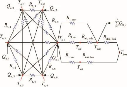
Fig.2 Thermal network diagram of heat transfer for UAV.
The radiation resistance between the devices is not marked in the figure because of the crowded icons,but the way of their label is similar to R1,2.It should be noted that the heat transfer relationship,as shown in Fig.2,is only the one of Equipment 1 and the other thermal nodes.It is very similar for Equipment 2-Equipment 6,so the total thermal network diagram cannot be given totally here.
2.2.Multi-node transient thermal model and boundary conditions
2.2.1.Thermal network model
Considering the above assumptions,the general equation of heat transfer for the equipment can be expressed as follows:
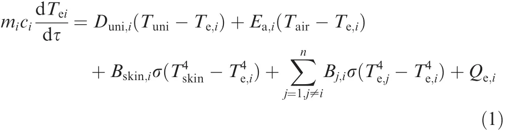
where mi,ciand Qe,iare the mass,the specific heat and the inner heat source of Equipment i,respectively;τ is time;1/Duni,iis the contact thermal resistance between Equipment i and the cold plate;1/Ea,iis the thermal resistance of convection;Bskin,iand Bj,iare the equivalent radiation factors;σ is the Stefan-Boltzmann constant,5.67 × 10-8W/(m2·K4);n is the number of equipment,n=6.
The average temperature of cabin air is given by the following equation:

where mairand cvare the mass and the specific heat of air,respectively;1/Euni,aand 1/Eskin,aare the thermal resistances of convection;hairis the specific enthalpy of air.
The temperature of skin can be given as follows:

where mskin,cskinand Askinare the mass,the specific heat and the area of the UAV skin,respectively;1/Ebou,skinand 1/Eair,skinare the convection thermal resistances of outside and inside;εskinand αskinare the external emissivity and absorptivity of skin,respectively;ξskinis the index which takes into account the self-shadowing of the skin from the direct solar radiation.
The temperature of the cold plate can be obtained as follows:

where muni,cuniand Auniare the mass,the specific heat and the area of the heat-pipe cold plate,respectively;1/Ebou,uniis the outside convection thermal resistance; εuniand αuniare the externalemissivity and absorptivity of the cold plate,respectively.
The equivalent radiation factor between node i and j,Bi,j,is calculated by the following equation:

where Fi,jis the angle factor;Aiand εiare the area and the emissivity of node i,respectively.
The boundary layer temperatures outside the vehicle,Tbou,can be obtained with Eq.(6)4:

where Tatmis the atmospheric temperature at the flight altitude;Ma is the flight Mach number.
The standard atmospheric parameters specified in ISA-1976 are used in this paper to obtain the atmospheric temperature and pressure change with the altitude.18
2.2.2.Radiative fluxes
The radiation heat fluxes,qR,i,i=1,2,...,5,can be calculated by the following equations:
(1)Direct solar radiation heat flux7

where τatmis the attenuation coefficient;I0is the average solar radiation intensity;e is the orbital eccentricity of the earth,e=0.0934;wTis the day angle.
(2)Infrared and diffuse radiation heat fluxes of atmosphere19

where Tskyis the equivalent blackbody temperature of atmosphere;pwis the partial pressure of vapor;Tais the environ-mental temperature near the UAV;γ is the solar elevation angle;Ptis the atmospheric transparency;m is the air quality.
(3)Re flected solar radiation and infrared radiation heat fluxes of the earth19

where ρGis the average reflection coefficient of ground;IDis the direct solar radiation at ground level;τatm,Gis the attenuation coefficient of ground reflected radiation;TGis the approximate temperature of earth.
2.2.3.Convective heat transfer
The Prandtl number,Pr,the Grashof number,Gr,the Rayleigh number,Ra,and the Reynolds number,Re,can be obtained by

where μ is the absolute viscosity;cpis the specific heat at constant pressure;λ is the thermal conductivity;g is the gravity;ρ is the density;α is the volumetric expansion coefficient;Twalland Tfluidare the temperatures of wall and fluid respectively;vfluidis the velocity of the fluid;Lchais the characteristic length.
Empirical equations are used to calculate the forced convective heat transfer coefficient of the external skin and the natural convective heat transfer coefficient in the cabin.The correlations to calculate the Nusselt number of forced convection are described as follows20:

The Nusselt number for the natural convection in the cabin can be given by Eq.(10)20,21

2.3.Model validation
2.3.1.Experimental apparatus
An experimental apparatus was set up to validate the above thermal equations.As shown in Fig.3,the experimental apparatus can produce a low-temperature and low-pressure environmentin its simulation chamber controlled by a temperature control unit and a pressure control unit.Hence the outside flight environmental parameters,Tenvand Penv,can be simulated in this chamber.A tested UAV electrical equipment cabin was placed in the experimental simulation chamber.
The temperature control unit was composed of a refrigeration system and a heating system.The pressure control unit included a vacuum pump and an inlet valve.Temperature sensor measured the real-time temperature measurement data,which were recorded by a data logger.A recirculation fan was used to circulate the air in the experimental simulation chamber.The average wind velocity in the experimental simulation cabin could be calculated according to its cross-sectional area and the recirculation air flow rate.
The physical parameters of electrical equipment are listed in Table 1.The thermal physical parameters of the cold plate,the skin and the equipment are listed in Table 2.
The cold plate can realize an isothermal effect by the buried heat pipes,as shown in Fig.4.The dotted lines show the positions of the heat pipes buried in the cold plate.A previous experiment was conducted to test the uniform effect of cold plate.Ten temperature sensors were placed at the positions A1to A5and B1to B5.The power of thermal resistance was controlled to simulate the heating effect of electrical equipment.The results show that the temperature difference at each end of the heat pipe was less than 1°C.Therefore,the cold plate can be considered as an isothermal temperature node.
The contact thermal resistance has a great influence on the simulation results in the thermal net analysis.According to the installation pressure between the equipment and the cold plate,the contact thermal conductivity can be determined with Table 3 by using the linear difference method.22,23Then the contact thermal resistance can be obtained correspondingly.
2.3.2.Temperature correction
In this study,the temperature measurement accuracy of thermocouple was corrected before the experiment.A standard thermocouple and the least square method were used to deal with the experimental data.Supposing that the jth temperature measured by the standard thermocouple is yj,and the corresponding temperature measured by the experimental thermocouple is xj,we transform the value measured by the experimental thermocouple into the standard value through the following linear fitting formula:

Fig.3 Flowchart of experimental apparatus.

Table 1 Physical parameters of devices.
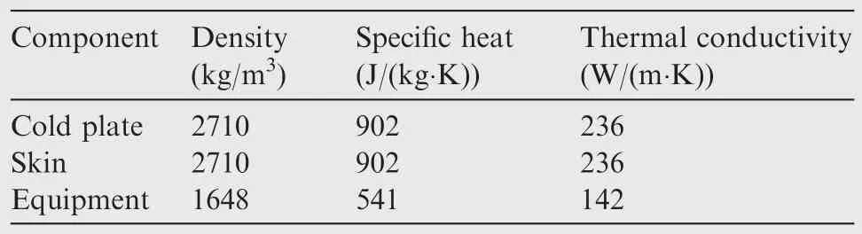
Table 2 Thermal physical parameters.

Fig.4 Positions of heat pipes in cold plate.
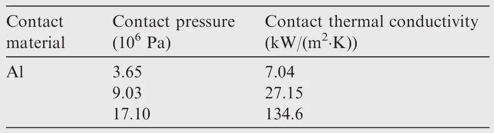
Table 3 Relationship between contact thermal conductivity and contact pressure.

By measuring a series of values at different temperatures,the value ofandcan be given as follows:

wherex andare the average values of xjand yj,respectively;n is the total number of measured data.
2.3.3.Experimental conditions
The temperature and pressure control curves in the environment simulation chamber are shown in Fig.5.
The outside radiation heats were not considered in this experiment.In addition,the outside convection effect was only caused by the air velocity in the simulation chamber,so it cannot reflect the real outside convection caused by the flight Mach number.
2.3.4.Comparison between simulation and experimental results
According to the experimental conditions,a thermodynamic analysis code based on the proposed multi-node transient heat model was developed to simulate the whole experimental process.The experimental results were used to evaluate the proposed model.Fig.6 shows the comparison results of Equipment 1-Equipment 4.
The above comparisons show that the change trend of simulation temperature curves matches the experimental temperature curves very well,and the maximum absolute difference between the experimental data and the simulation results is about 7°C in Fig.6(d).Based on the above comparison results,the thermal analysis code is reliable.Therefore,it can be used to predict the thermal responses of electrical equipment cabin under a certain flight mission.
3.Prediction results

Fig.5 Control curves of experimental temperature and pressure in chamber.

Fig.6 Comparison between experimental and simulation results for electrical equipment.
The thermal responses of equipment and cabin air in a hypothetical flight mission will be studied by using the above simulation code.The external radiation and convection effect in Eqs.(8)–(10)will be taken into account.Fig.7 shows the flight mission curves,in which the flight altitude will reach to 20000 m,and the flight duration will be more than twelve hours.
In this section,the influence of the flight speed and external radiation on the heat transfer will be analyzed by the simulation comparison.The simulation conditions of flight speed and external radiation will be summarized into the following three simulation cases,see Table 4.
According to the above three simulation conditions,the simulation results are given in the following.
3.1.Temperature prediction results in Case 1
Fig.8 shows the temperature changes in Case 1.Fig.8(a)is the temperature response curves of the atmosphere,the cabin air,the boundary and the skin.Fig.8(b)is the temperature responses of electrical devices and the cold plate.
Compared with the results in Fig.6,the lower limits of temperature in Fig.8 are a little lower because the ambient temperature of Case 1 is lower.
3.2.Temperature prediction results in Case 2
Fig.9 shows the temperature changes in Case 2.Compared with the results in Fig.8,we can observe that:

Fig.7 Flight mission curves.

Table 4 Simulation cases.
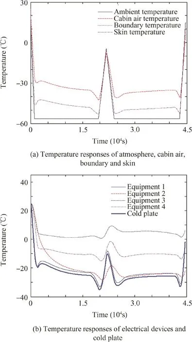
Fig.8 Temperature changes of nodes in Case 1.
(1)In the altitude of 20000 m,the temperature change range of cabin air is from-30 °C to-10 °C,and the one of skin is from-40 °C to 0 °C.The total temperature levels in Fig.9(a)increase obviously compared with Fig.8(a)under the effect of the external radiation fluxes.
(2)With the external radiation effect,the upper-lower limits of device temperature also become higher than the ones in Case 1.But they have the same temperature change trend.
(3)Because of the simulation condition of low flight speed,the outside heat transfer coefficient is small,and its value is about 10 W/(m2·K).
(4)In Fig.9(b),the temperature of the cold plate is lower than the one of the equipment.The temperature values of equipment are different because of different thermal resistances and internal heat source.

Fig.9 Temperature changes of nodes in Case 2.
(5)In Figs.8(a)and 9(a),the curves of ambient temperature and boundary temperature coincide.
3.3.Temperature prediction results in Case 3
Fig.10 shows the temperature changes in Case 3.Compared with the results in Fig.9,we can observe that:
(1)In the simulation condition of high flight speed,Tairand Tskindecrease,and tend to be stable at-30°C and-40°C,respectively.Tairdecreases to 0–20 °C,and Tskindecreases to 0–40 °C.
(2)The upper-lower limits of temperature change range become much smaller than the ones in Case 1.The average temperature level is greatly pulled down from Figs.9(b)to 10(b).Therefore,the external convection effect plays a very important role in the temperature control of electrical equipment cabin.
(3)The temperature changes of equipment lag behind the ones of the cold plate.
(4)All of the temperatures quickly reach a steady state because of strong convection,and the value of external convective heat transfer coefficient is about 280 W/(m2·K).

Fig.10 Temperature changes of nodes in Case 3.
4.Conclusions
The study on cabin temperature response is of great significance for the thermal management of UAV.A multi-node transient model is established and calibrated by an experimental apparatus in this paper.A thermal simulation code for the UAV is built based on the calibrated model.It can predict and study the thermal response and thermal balance level of electrical equipment.
(1)According to the features of HALE UAV,a multi-node transient model,which includes the internal and external heat transfer factors,is established in this paper.
(2)An experimental bench with six electrical devices was installed in the simulation chamber.A typical flight condition was simulated by controlling the temperature and pressure in the chamber.The established model is corrected according to the experimental results.Then a thermodynamic analysis code is programmed to predict the thermal changes of electrical equipment cabin.
(3)Three simulation cases are conducted.By comparison of prediction results of Case 1 and Case 2,the external radiation has a certain effect on the thermal changes of electrical equipment cabin.It will raise the temperature level to some extent,but its impact is limited.
(4)The high flight speed condition in Case 3 has an obvious influence on the thermal responds of electrical equipment cabin.The total temperature level is pulled down greatly due to the effect of outside high-speed forced convection even with the presence of low atmospheric pressure and low density.
Acknowledgments
The authors gratefully acknowledge the financial support of National Key R&D Program of China (No.2017YFB1201100).
1.Jamison L,Sommer GS,Iii IRP.High-altitude airships for the future force army.Santa Monica:Rand Corporation;2005.
2.Goraj Z,Frydrychiewicz A,Winiecki J.Design concept of a highaltitude long-endurance unmanned aerial vehicle.Aircr Des 1999;2(1):19–44.
3.Barbosa R,Escobar B,Sanchez VM,Hernandez J,Acosta R,Verde Y.Sizing of a solar/hydrogen system for high altitude long endurance aircrafts.Int J Hydrogen Energy 2014;39(29):16637–45.
4.Romeo G,Frulla G,Cestino E.Design of a high-altitude longendurance solar-powered unmanned air vehicle for multi-payload and operations.Proc Inst Mech Eng,Part G:J Aerospace Eng 2005;221(2):199–216.
5.Peng WG,He YR,Wang XZ,Zhu JQ,Han JC.Thermal protection mechanism of heat pipe in leading edge under hypersonic conditions.Chin J Aeronaut 2015;28(1):121–32.
6.Su XH,Xu F.Transient thermal analysis of a plate fin heat sink with Green’s function.Chin J Aeronaut 2011;24(3):243–8.
7.Yao W,Lu X,Wang C,Ma R.A heat transient model for the thermal behavior prediction of stratospheric airships.Appl Therm Eng 2014;70(1):380–7.
8.Gao XZ,Hou ZX,Guo Z,Liu JX,Chen XQ.Energy management strategy for solar-powered high-altitude long-endurance aircraft.Energy Convers Manage 2013;70:20–30.
9.Shang B,Ma Y,Hu R,Chao Y,Hu JY,Luo XB.Passive thermal management system for downhole electronics in harsh thermal environments.Appl Therm Eng 2017;118:593–9.
10.Phillips AL,Wert KL.Skin as radiator-passive thermal management for high altitude long endurance-UAVs.34th intersociety energy conversion engineering conference.Vancouver:SAE Technical Paper;1999.p.2501-8.
11.Alam MI,Pant RS.A multi-node model for transient heat transfer analysis of stratospheric airships.Adv Space Res2017;59(12):3023–35.
12.Lemmens YCJ,Benoit T,Roo RD,Verbeke J.Real-time simulation of an integrated electrical system of a UAV.Cheminform 2014;36(14):2637–40.
13.Wu BH,Cui D,He XD,Zhang DH,Tang K.Cutting tool temperature prediction method using analytical model for end milling.Chin J Aeronaut 2016;29(6):1788–94.
14.Lu P,Geng Q.Real-time simulation system for UAV based on Matlab/Simulink.International conference on computing,control and industrial engineering.Piscataway:IEEE Press;2011.p.399-404.
15.Baïri A.Transient thermal characteristics of airborne electronic equipment with discrete hot bands in square cavities.Appl Energy 2008;85(10):951–67.
16.Qiu ZZ,Pang LP,Li GX,Zhang HL.Numerical simulation of cabin ventilation subsystem in space station oriented real-time system.Chin J Aeronaut 2017;30(6):1809–17.
17.Alyanak EJ,Allison DL.Fuel thermal management system consideration in conceptual design sizing.57th AIAA/ASCE/AHS/ASC structures,structural dynamics,and materials conference;2016 January 4-8;San Diego,USA.Reston:AIAA;2016.
18.Goswami DY,Kreith F,Kreider JF.Principles of solar engineering.Boca Raton:CRC Press;2015.
19.Dai QM,Fang XD,Li XJ,Tian LL.Performance simulation of high altitude scientific balloons.Adv Space Res 2012;49(6):1045–52.
20.Dewitt DP,Incropera FP.Fundamentals of heat and mass transfer.New York:John Wiley&Sons;2002.p.27–139.
21.Baïri A,García de María JM,Baïri I,Laraqi N,Zarco-Pernia E,Alilat N.2D transient natural convection in diode cavities containing an electronic equipment with discrete active bands under constant heat flux.Int J Heat Mass Transfer 2012;55(19–20):4970–80.
22.Min GR.Thermal control technology of satellite.Beijing:China Astronautic Publishing House;1991[Chinese].
23.Yang SM,Tao WQ.Heat transfer.Beijing:Higher Education Press;2006[Chinese].
 CHINESE JOURNAL OF AERONAUTICS2018年6期
- CHINESE JOURNAL OF AERONAUTICS的其它文章
- An efficient aerodynamic shape optimization of blended wing body UAV using multi- fidelity models
- Effect of multiple rings on side force over an ogive-cylinder body at subsonic speed
- Experimental investigation on static/dynamic characteristics of a fast-response pressure sensitive paint
- Takagi-Sugeno fuzzy model identification for turbofan aero-engines with guaranteed stability
- Experimental study on film cooling performance of imperfect holes
- Mechanism of stall and surge in a centrifugal compressor with a variable vaned diffuser