
Encapsulation of Co metal by nitrogen doped porous carbon for catalytic removal of organic pollutants
2018-07-23 01:42WANGGuanlongBIChenxiCHENShuoQUANXieYUHongtao
大连理工大学学报 2018年4期
WANG Guanlong,BI Chenxi,CHEN Shuo,QUAN Xie,YU Hongtao
(Key Laboratory of Industrial Ecology and Environmental Engineering, MOE, Dalian University of Technology, Dalian 116024, China )
Abstract: Sulfate radical which is usually obtained by peroxymonosulfate (PMS) activation, has attracted much interest in the research of organic pollutant degradation for its high oxidative capability. Herein, a Co@nitrogen doped porous carbon (Co@NPC) core-shell catalyst is prepared using ZIF-67 as the precursor by two-step heating treatment. Different carbonization temperatures are chosen to tune the structure and composition of carbon shell, and its relationship with catalytic performance is investigated. The results show that the mesopore volume and the carbon shell thickness increase gradually with the increase of carbonization temperature, while the catalytic performance is enhanced with the increasing ratio of mesopore volume to carbon shell thickness. The Co@NPC carbonized at 850 ℃ performs best for phenol degradation, whose kinetic constant for phenol degradation is 110.8 times higher than that of heterogeneous Co3O4 and even 4.6 times higher than that of the reported optimum homogeneous Co2+ for PMS activation. Moreover, the Co@NPC displays good stability and obvious reduction of Co leaching when the number of carbon layer is higher than 3. The mesopore volume and thickness of carbon shell play significant roles in the PMS activation, while the content of graphitic N could also influence the catalytic performance.
Key words: peroxymonosulfate (PMS); sulfate radical; nitrogen doped porous carbon; core-shell catalyst; phenol degradation
0 Introduction
Encapsulating the Co nanoparticles into a porous shell to form a core-shell structure may alleviate the above problems[9]. On the one hand, the porous shell could impede the aggregation and leaching of Co nanoparticles, and protect the inside Co nanoparticles from outside harsh environment[10]. On the other hand, the porous structure facilitates the transport of reactant and products[11]. Zeng,etal.[9]constructed a yolk-shell Co3O4@metal-organic frameworks (MOFs) catalyst for PMS activation, for which the degradation efficiency of 4-CP reached almost 100% within 60 min compared to only 59.6% under the same conditions for bare Co3O4nanoparticles. However, in that work the MOFs shell showed no catalytic activity. The catalytic efficiency of core-shell catalyst would be largely improved if both core and shell could serve as the active sites for PMS activation.
Carbon materials are believed to be ideal materials for constructing the shell of core-shell catalysts due to its large surface area, good chemical stability and low cost[12]. Especially, the intrinsic catalytic capability of carbon materials makes it possible for them to participate the catalytic reaction[13]. Recently, the carbon materials such as activate carbon, graphene and porous carbon have shown their capability in PMS activation. Moreover, the heteroatom doping method such as the nitrogen doping was found to further enhance the catalytic efficiency of carbon towards PMS because the nitrogen with higher electronegativity than carbon could induce high positive charge on carbon and effectively activate it, thus promoting the adsorption and activation of negatively charged PMS on carbon[14-15].
Inspired by it,constructing a core-shell catalyst with nitrogen doped porous carbon as the shell and Co nanoparticles as the core may form a highly efficient and stable catalyst for PMS activation. The Co encapsulated by nitrogen doped porous carbon possesses several advantages in PMS activation: (1) It was reported the interactions between Co core and carbon-shell could reduce the work function of carbon shell and enhance its electron-donating capability in the Co@carbon core-shell structure[16]. Hence, the doped nitrogen and encapsulated Co may synergistically modify the electronic structure of carbon and enhance the catalytic activity of carbon, which is beneficial for the enhanced PMS activation on carbon. (2) The porous carbon shell is favorable for the transport of the PMS and products. (3) The porous carbon shell protects the Co from aggregation and leaching, improving the stability of catalysts[17]. To realize high PMS catalytic efficiency on this core-shell catalyst, it is critical to rationally design and regulate the carbon shell. The thin carbon shell is favorable for the mass transfer and the interaction between carbon shell and Co core, while the thick carbon shell could alleviate the metal leaching. However, facile and effective regulation over the shell structure during the development of the core-shell catalyst remains a challenge.
The metal-organic frameworks (MOFs), composed of metal cluster and various organic ligands, are ideal precursors to construct the metal@carbon nanostructure through the carbonization treatment[18-19]. Moreover, the carbon shell thickness and composition could be controlled via controlling the carbonization process and temperature[20-21]. In this work, the ZIF-67, a MOF rich in Co and N (Co content: 25.8%, N content: 26.7%), was used as the template to construct the Co@nitrogen doped porous carbon (Co@NPC). Different carbonization temperature (750 ℃, 850 ℃ and 950 ℃) were chosen to prepare the carbon shell with different structures and compositions. The phenol, bisphenol A and rhodamine B were used to evaluate the catalytic performance of Co@NPC for PMS activation and the effect of carbon structure and composition on catalytic performance was studied. Furthermore, the possible catalytic mechanism was explored.
1 Experiment
1.1 Preparation of ZIF-67
The typical preparation process of ZIF-67 was as follows. Solution A: 2.25 g Co(NO3)2·6H2O was dissolved in 15 mL ultrapure water. Solution B: 27.5 g 2-methylimidazole was dissolved in 100 mL ultrapure water. Then the solution A was slowly added into the solution B and stirred for 6 h. The catalysts were obtained through centrifuging at 8 000 r/min for 10 min. The resulting catalysts were then washed with methanol and ultrapure water respectively, and finally dried at 50 ℃ in oven.
1.2 Preparation of Co@NPC
Co@NPC was prepared through carbonization of ZIF-67. Typically, for the preparation of Co@NPC, the powder of ZIF-67 was heated to 450 ℃ (5 ℃·min-1) in a tube furnace under Ar gas flow, and maintained at this temperature for 2 h. This process involved the collapse of the framework and the formation of new component. Then the temperature is elevated to 750 ℃, 850 ℃ and 950 ℃ respectively and maintained at it for 1 h to realize the catalytic graphitization by Co metal. This two-step calcination resulted in the final Co@NPC core-shell catalyst. For convenient description, the Co@NPC carbonized at 750 ℃, 850 ℃ and 950 ℃ were denoted as Co@NPC-750, Co@NPC-850 and Co@NPC-950.
1.3 Characterization
The morphologies of catalysts were revealed by field emission scanning electron microscope (Hitachi S-4800, FE-SEM) and transmission electron microscopy (FEI-Tecnai G220, TEM). The structure properties of the catalysts including the crystal structure and carbonization degree were performed by X-ray diffraction (Shimadzu LabX XRD-6000, XRD) and Raman spectrum (Renishaw Micro-Raman System 2000 Spectrometer). The pore structure and specific surface area of catalysts were determined through N2adsorption-desorption isotherms at 77 K with a Quadrasorb instrument. The Co content was measured by ICP-AES (Optima 2000 DV). The element composition and species distribution were characterized by X-ray photoelectron spectroscopy (XPS) got from a VG ESCALAB 250 spectrometer using a non monochromatized AlKα X-ray source (1 486.6 eV).
1.4 Evaluation of catalytic performance
The catalytic performance of catalysts was evaluated through pollutant removal. Initially, 2.5 mg Co@NPC catalyst was dispersed in 50 mL solution containing 20 mg·L-1phenol. Phosphate buffer (1 mmol·L-1, pH 7) was added into the solution to maintain the pH at 7. The solution was stirred to reach the adsorption-desorption equilibrium, and then 1.6 mmol·L-1PMS was added to initiate the reaction. 1 mL solution was withdrawn at the given time and filtered through a 0.22 μm millipore film for further analysis. 0.1 mL methanol was immediately injected into the reaction solution for scavenging the residual radicals. The effects of catalyst dosage, PMS loading and pH on degradation efficiency of phenol were evaluated. The pH of solution was adjusted by adding 0.1 mmol·L-1HCl or NaOH. In the reusability test of catalyst, the used Co@NPC was collected via vacuum filtration and washed with ultrapure water (resistivity is bigger than 18 MΩ·cm).
1.5 Analytic methods
The concentrations of phenol and bisphenol A (BPA) were analyzed by a high performance liquid chromatography (HPLC, Waters). The mobile phase was 30% methanol and 70% ultrapure water at a flow rate of 1 mL·min-1. The organics were separated by a C-18 column and determined by a PDA detector. TOC concentration of aliquot samples was determined using a total carbon analyzer (Shimadzu TOC-VCPH, Japan). The concentration of rhodamine B (RhB) was measured by a UV-vis spectrometer atλ=552 nm.
2 Results and discussion
2.1 The characteristics of Co@NPC
The morphologies of ZIF-67 and Co@NPC were characterized using SEM and TEM. As shown in Fig. 1, SEM images of ZIF-67 and Co@NPC-850 illustrate the similar polyhedral structure, indicating the carbonization process does not destroy the structure of the original morphology of ZIF-67. The average size of ZIF-67 is around 300 nm, yet reduced to around 100 nm for Co@NPC-850, which is possibly owing to the changes of the precursor structure and the loss of oxygen containing groups during the carbonization process. TEM images further show the microstructure of Co@NPC carbonized at different temperatures (Fig. 2). It is found that the Co nanoparticle with a lattice fringe of 0.208 nm is completely encapsulated by carbon cages in 3-10 layers. The lattice fringe of carbon layers is 0.342 nm, which is assigned to (002) plane of graphene. These results suggest that the as-synthesized Co@NPC samples demonstrate a core-shell structure and retain a highly ordered structure of graphitic structure. The carbon layers of Co@NPC-750, Co@NPC-850 and Co@NPC-950 are 3, 5 and 8, respectively. The Co nanoparticles in Co@NPC-950 could not be clearly observed on TEM images because they are completely encapsulated by relatively thick carbon layers. These results reveal that the thickness of graphitic carbon increases with the increasing carbonization temperatures and thereafter contributes to an increased carbon layers.
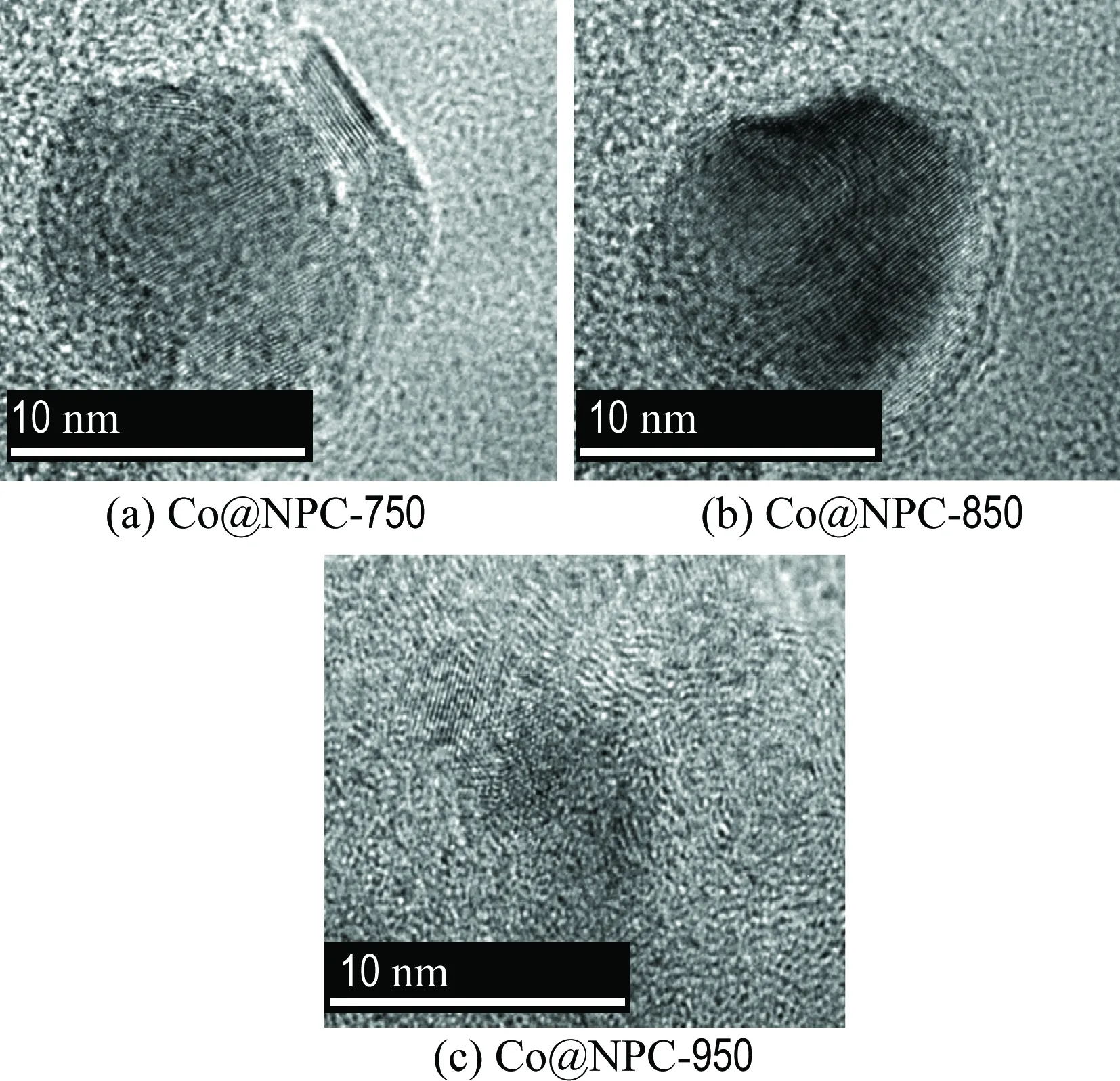
Fig.2 The TEM images of Co@NPC
Raman analysis was also carried out to get structural information of Co@NPC. As shown in Fig. 3(a), the characteristic D band (defect carbon structure) and G band (graphitized carbon structure) appear at 1 360 cm-1and 1 580 cm-1, respectively. The relative intensity of the D and G peaks (ID/IG) of Co@NPC decreases with the increment of carbonization temperatures, suggesting the higher carbonization temperature results in better graphitization degree. Furthermore, XPS measurements were conducted to reveal the element composition of Co@NPC. As shown in Fig. 3(b), the characteristic peaks of Co, N and C are clearly observed on all Co@NPC samples, illustrating both Co and N are successfully doped into carbon lattice. Moreover, the Co and N contents gradually decrease with the increase of carbonization temperature (Tab. 1), which is ascribed to the growing thick carbon layers and the loss of N-containing groups.
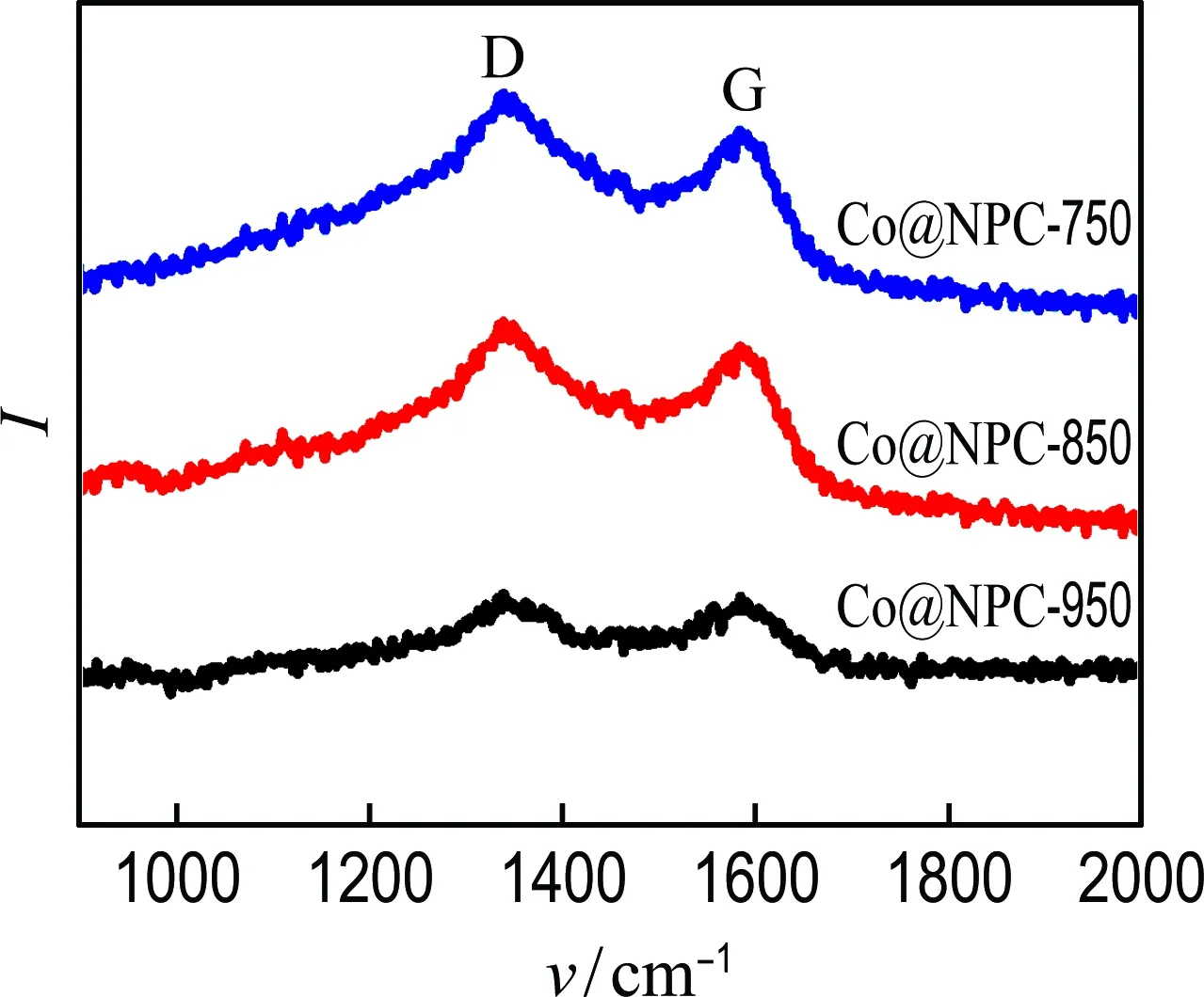
(a) Raman spectra

(b) XPS spectra
Fig.3 Raman spectra and XPS spectra of Co@NPC-750,Co@NPC-850 and Co@NPC-950
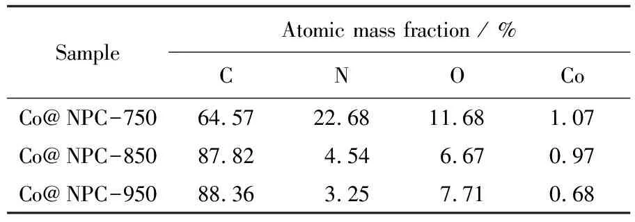
Tab.1 Element composition of Co@NPC
2.2 The catalytic performance of Co@NPC
The catalytic performance of Co@NPC for PMS activation was evaluated using phenol as the model pollutant. For comparison, the homogeneous Co2+and heterogeneous Co3O4were employed as references. Fig. 4(a) shows that almost no phenol is removed by PMS alone after 60 min, meaning the PMS itself could hardly oxidize the phenol. Less than 10% phenol is removed when only the catalysts are added into the solution, which is probably attributed to the adsorption of phenol on catalyst. After the addition of PMS, the phenol concentration rapidly decreases. The Co@NPC-850/PMS performs best with almost complete removal (about 100%) of phenol within 15 min, followed by the Co@NPC-950/PMS and Co@NPC-750/PMS, which could almost completely remove phenol within 30 min and 60 min, respectively. Under the same catalyst dosage, the Co@NPC-850/PMS performs better than heterogeneous Co3O4/PMS which removes only 30% phenol within 40 min, and even outperforms the homogeneous Co2+/PMS (the most effective PMS catalytic system) which removes about 100% phenol within 40 min.
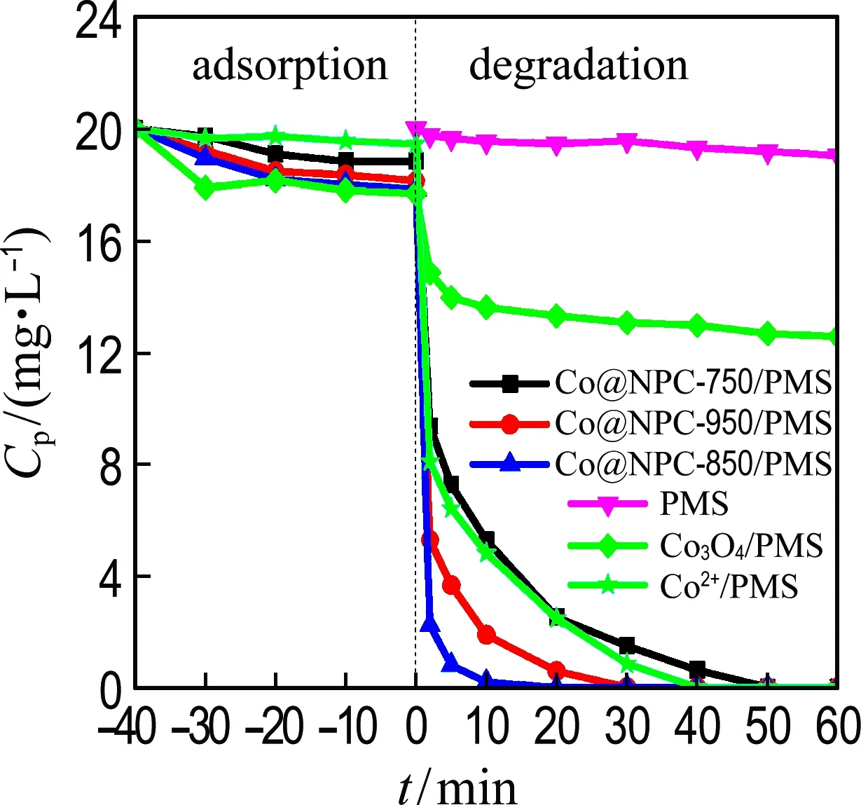
(a) PMS activation by Co@NPC
(b) Kinetic constant
Fig.4 Catalytic performance for phenol degradation (Ccat=0.05 g·L-1,cPMS=1.6 mmol·L-1,Cpoll=20 mg·L-1,θ=25 ℃, initial pH=7.0)
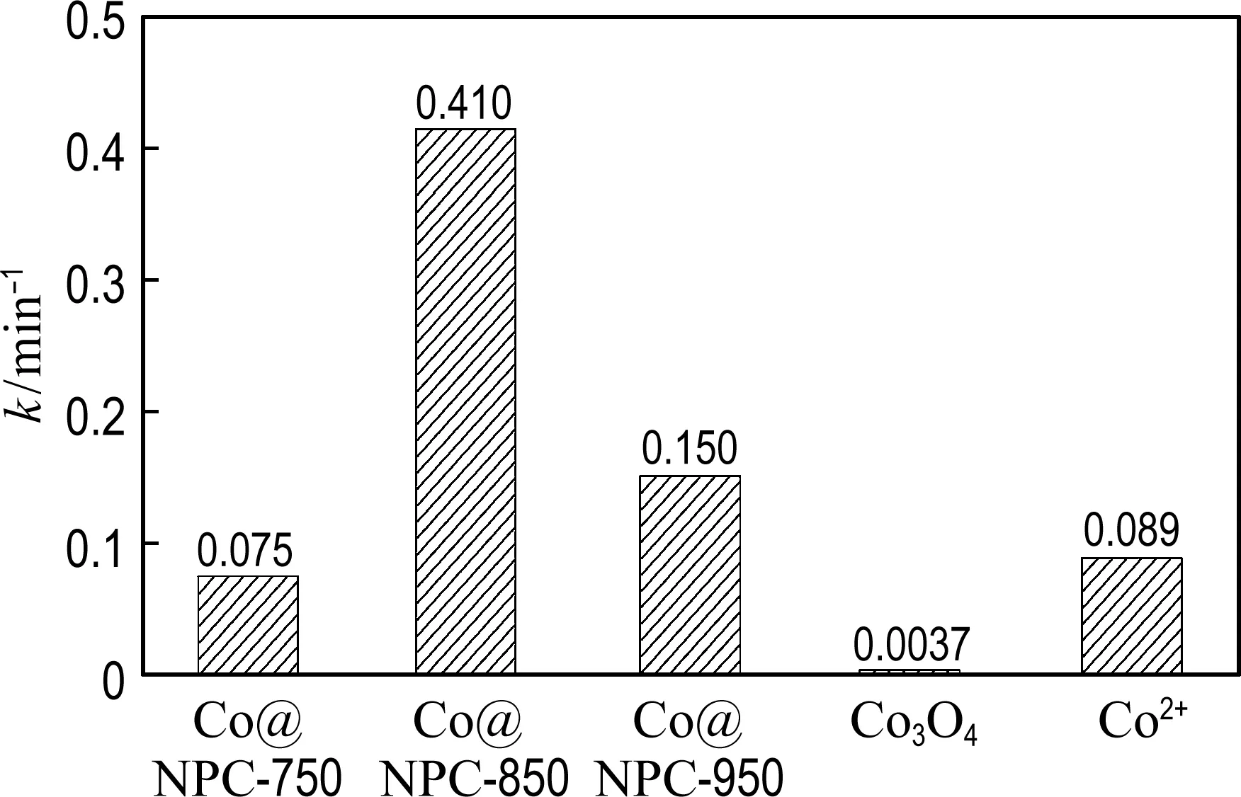
The degradation process of phenol by Co@NPC/PMS is fitted well with the pseudo-first-order reaction. As shown in Fig. 4(b), the kinetic constants of phenol oxidation on Co@NPC-750, Co@NPC-850, Co@NPC-950, homogeneous Co2+and heterogeneous Co3O4are 0.075 min-1, 0.410 min-1, 0.150 min-1, 0.089 min-1and 0.003 7 min-1, respectively. The Co@NPC-850 shows best performance for PMS activation, whose catalytic efficiency for phenol degradation is 4.6 times and 110.8 times that of homogeneous Co2+and heterogeneous Co3O4, respectively.
Other recalcitrant pollutants including BPA and RhB were also selected to evaluate the catalytic performance of Co@NPC (Fig. 5). The results show that nearly 100% BPA and RhB are removed by Co@NPC/PMS within 30 min. The kinetic constants for the degradation of phenol, BPA and RhB reach 0.41 min-1, 0.87 min-1and 0.16 min-1, respectively. It indicates that the Co@NPC/PMS system is capable of removing various refractory organic pollutants.
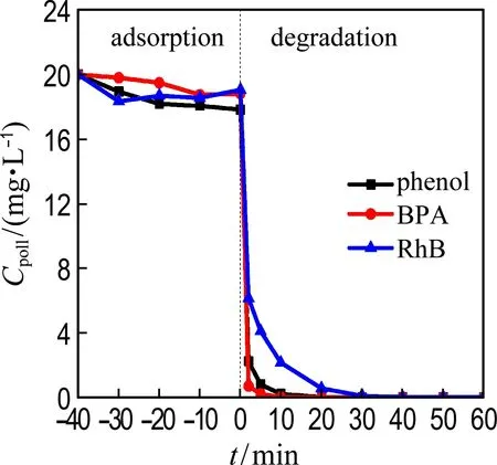
(a) Co@NPC/PMS system
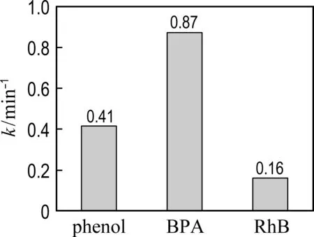
(b) Kinetic constant
Fig.5 Catalytic performance for degradation of different pollutants (Ccat= 0.05 g·L-1,cPMS=1.6 mmol·L-1,Cpoll=20 mg·L-1,θ=25 ℃, initial pH=7.0)
2.3 The effects of catalyst dosage, PMS concentration and pH on the catalytic performance of Co@NPC
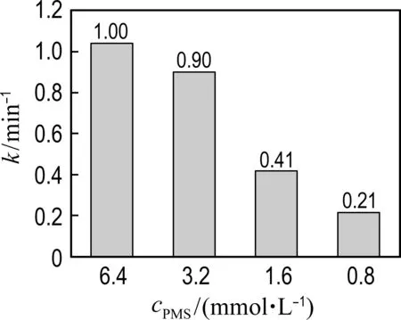
As shown in Fig. 6(a), the phenol degradation efficiency is enhanced with the increase of catalyst concentration. Fig. 6(a) shows that the kinetic constant of Co@NPC for phenol degradation increases from 0.071 min-1at 0.01 g·L-1catalyst dosage to 1.00 min-1at 0.10 g·L-1catalyst dosage. The higher catalyst concentration could provide more active sites for radical generation, thus leading to better catalytic performance.
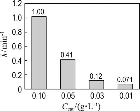
(a) Catalyst dosage
(b) PMS concentration

(c) pH
Fig.6 The effects of conditions on phenol degradation

(1)
(2)

2.4 The reusability and stability of Co@NPC
The reusability of Co@NPC catalysts for phenol degradation is presented in Fig. 7(a). The repetition use causes almost no decline of the catalytic activity of Co@NPC for phenol degradation, suggesting the good reusability of Co@NPC. To further evaluate the stability of Co@NPC, the Co leaching in each reaction cycle was detected. Fig. 7(b) shows that the Co leaching of Co@NPC/PMS system decreases gradually from 0.25 mg·L-1in the 1st run to 0.01 mg·L-1in the 5th run. This value is much lower than the National Standard for Co Discharge (GB 25467-2010, 1 mg·L-1). The low Co leaching of Co@NPC may be ascribed to the protective effect of carbon shell. Fig. 7(c) shows the Co leaching of the Co@NPC carbonized at different temperatures. It could be found the Co leaching obviously decreases when the carbonization temperature increases from 750 ℃ to 850 ℃. The Co leaching reaches 1.03 mg·L-1, 0.25 mg·L-1and 0.08 mg·L-1for the Co@NPC carbonized at 750 ℃, 850 ℃ and 950 ℃, respectively. The Co leaching is largely reduced when the carbon layer is more than 3.
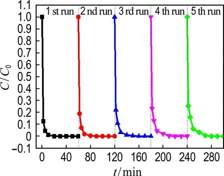
(a) The reusability of Co@NPC
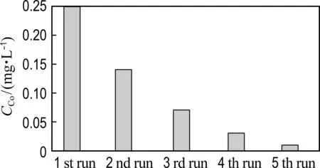
(b) Co leaching in each cycle
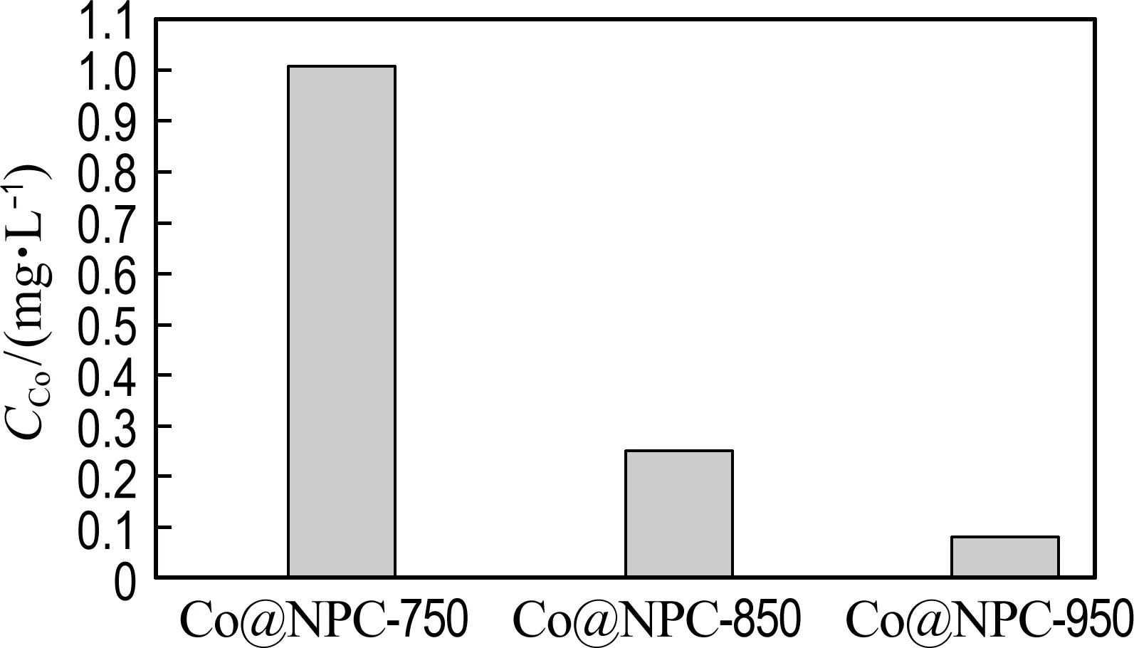
(c) Co leaching of different Co@NPC
Fig.7 The reusability of Co@NPC for phenol degradation as a function of time, Co leaching in each cycle and different Co@NPC
2.5 The contribution of radicals in Co@NPC/PMS system
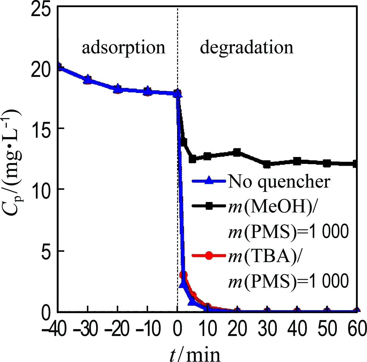
(a) Phenol degradation

(b) Kinetic constant
Fig.8 Phenol degradation as a function of time and kinetic constant of phenol degradation with the addition of TBA and MeOH
2.6 The possible catalytic mechanism of Co@NPC
It is generally accepted that the catalyst with high specific surface area is favorable for the catalytic reactions because it can offer abundant catalytic sites. For Co@NPC, their specific surface area follows the order of Co@NPC-950>Co@NPC-850>Co@NPC-750 (Tab. 2), whereas their reaction rate follows another order of Co@NPC-850>Co@NPC-950>Co@NPC-750. This result suggests the surface area of Co@NPC catalyst is not the primary factor responsible for its catalytic behavior, and other factors may dominate the performance of catalysts. Moreover, it is noted the mesopore volume of Co@NPC increases gradually with the increase of carbonization temperature. The higher mesopore volume is beneficial for the reactant transport.
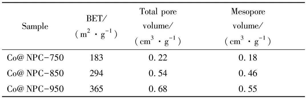
Tab.2 BET value, total pore volume and mesopore volume of Co@NPC
As reported in previous work, the graphitic N may greatly influence the catalytic activity of N doped carbon in PMS activation[21]. To check the possible influence of graphitic N, the XPS spectra were performed to investigate the N species of Co@NPC. The four peaks corresponding to graphitic-N (401.1 eV), pyridinic-N (398.5 eV), pyrrolic-N (400.5 eV) and Co-N coordination site (Co-Nx) (399.2 eV)[23]respectively are present in each Co@NPC. The content of N species in different Co@NPC was summarized in Tab. 3, which was calculated from the total N content and their respective proportion. Tab. 3 shows that the Co@NPC-750 possesses higher graphitic N content than that of Co@NPC-950, but its catalytic activity is poorer. The results demonstrate the graphitic N is not the critical factor for PMS activation. In addition, the occurrence of Co-Nxsuggests the Co core could produce the influence on the carbon shell, whereas with the increase of carbonization temperature, the Co-Nxcontent decreases gradually, suggesting the thicker carbon shell restricts the interaction between Co and carbon.
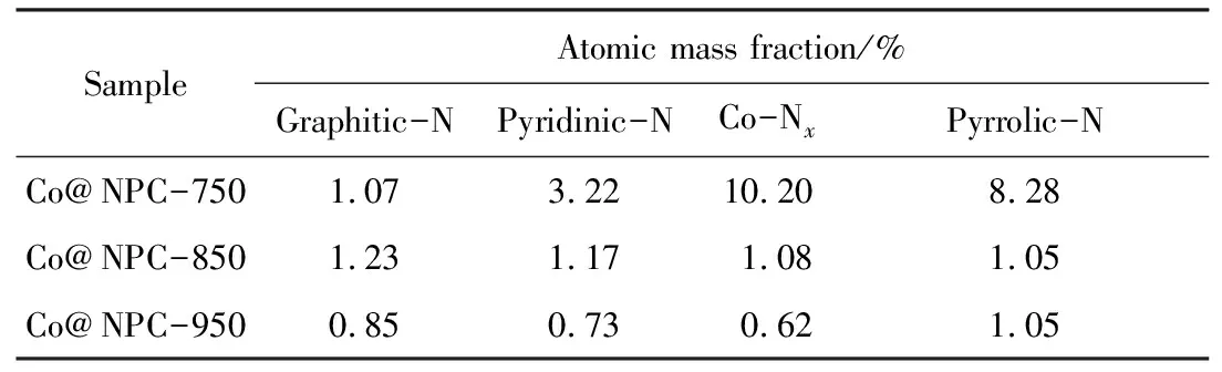
Tab.3 Content of different N species in Co@NPC
According to the result of Raman spectra, the graphitization degree of Co@NPC is enhanced with the increase of carbonization temperature. The enhanced graphitization degree means more sp2hybridized carbon structure is present in the carbon shell, and the sp2hybridized carbon structure could provide plentiful free-flowing π electrons for the electron transfer reaction. Moreover, the high graphitization degree is favorable for forming the thick carbon layers which inhibit the metal leaching. In this work, the Co@NPC-850 and Co@NPC-950 exhibits higher graphitization degree than Co@NPC-750, and the metal leaching of instable Co@NPC-750 is much higher than that of Co@NPC-850 and Co@NPC-950 (Fig. 9), leading to the higher catalytic activity of Co@NPC-850 and Co@NPC-950 than that of Co@NPC-750. Besides, the Co@NPC-850 and Co@NPC-950 possess higher mesopore volume than that of Co@NPC-750, which is beneficial for reactant transfer to the surface of catalyst.
Interestingly, although the Co@NPC-950 displays higher graphitization degree and mesopore volume than Co@NPC-850, the catalytic activity of Co@NPC-950 is still inferior to that of Co@NPC-850. This phenomenon may be explained by two possible reasons: Firstly, as shown in Tab. 3, the Co@NPC-850 possesses higher graphitic N content. Secondly, the TEM results indicate that the carbon layer of Co@NPC-950 is thicker than that of Co@NPC-850. Although the thick graphitic carbon layer can protect the Co from leaching, it enhances the resistance for reactant transfer and weakenes the interaction between Co core and carbon shell, thus resulting in the poorer catalytic performance of Co@NPC-950 than that of Co@NPC-850.
For better understanding the relationship between the structure of carbon shell and the catalytic activity of Co@NPC, the ratio of mesopore volume to carbon shell thickness for different Co@NPC was calculated. As shown in Fig. 9, the catalytic activity of Co@NPC is significantly enhanced with the increase of the ratio of mesopore volume to carbon shell thickness. This result confirms that the mesopore volume and the carbon shell thickness play important role in the catalytic performance of Co@NPC for PMS activation.
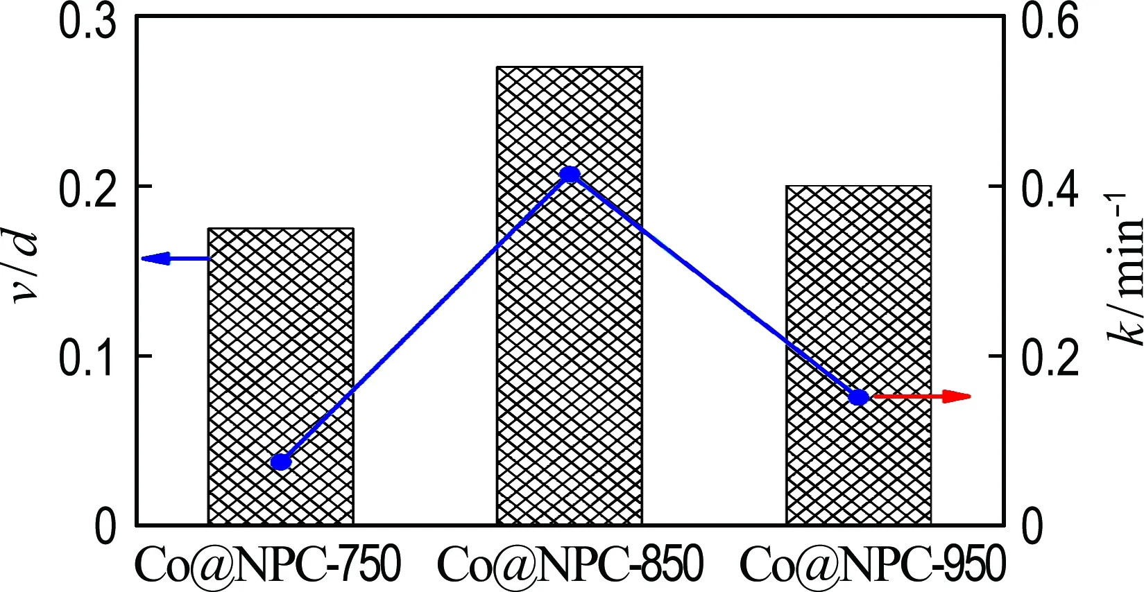
Fig.9 The relationship between the value of mesopore volume/carbon shell thickness (v/d) and the kinetic constant for phenol degradation on Co@NPC
3 Conclusion
Two-step heating treatment was employed for preparing the Co@NPC core-shell catalysts. The Co@NPC displays significantly enhanced catalytic activity with the increase of the ratio between mesopore volume and carbon shell thickness. The kinetic constant of the best Co@NPC is 4.6 times higher than that of homogeneous Co2+and 110.8 times higher than that of Co3O4. The Co@NPC also displays good stability in phenol degradation and less Co leaching (less than 0.25 mg·L-1). Sulfate radical is the main reactive radical present in the Co@NPC/PMS system responsible for the pollutant degradation. The mesopore volume and carbon shell thickness play key role in Co@NPC for PMS activation, while the graphitic N content also influences the catalytic performance.
