
A sand-production control system for gas production from clayey silt hydrate reservoirs
2019-01-12 05:55YanlongLiNngyouWuFulongNingGaowiHuChanglingLiuChangyinDongJinganLu
China Geology 2019年2期
Yan-long Li , Nng-you Wu *, Fu-long Ning , Gao-wi Hu Chang-ling Liu Chang-yin Dong,Jing-an Lu
a Key Laboratory for Gas Hydrate of Ministry of Natural Resources, China Geological Survey, Ministry of Natural Resources, Qingdao Institute of Marine Geology, Qingdao 266071, China
b Laboratory for Marine Mineral Resources, Qingdao National Laboratory for Marine Science and Technology, Qingdao 266071, China
c Faculty of Engineering, China University of Geosciences, Wuhan 430074, China
d School of Petroleum Engineering, China University of Petroleum, Qingdao 266580, China
e Guangzhou Marine Geological Survey, China Geological Survey, Ministry of Natural Resources, Guangzhou 510075, China
Keywords:
Natural gas hydrate
Hydrate exploitation
Sand-production management
Sand production
Sand control
Nodal system analysis
A B S T R A C T
Sand production is a crucial problem during the process of extracting natural gas from hydrate reservoirs.To deal with sand-production problems systematically, a sand-production control system (SCS) is first proposed in this paper, specialized for pore-distributed clayey silt hydrate reservoirs. Secondly, a nodal system analysis method (NSAM) is applied to analyze the sand migration process during hydrate exploitation. The SCS is divided into three sub-systems, according to different sand migration mechanisms, and three key scientific problems and advances in SCS research in China Geological Survey are reviewed and analyzed. The maximum formation sanding rate, proper sand-control gravel size, and borehole blockage risk position were provided for clayey hydrate exploitation wells based on the SCS analysis. The SCS sub-systems are closely connected via bilateral coupling, and coordination of the subsystems is the basis of maintaining formation stability and prolonging the gas production cycle. Therefore,contradictory mitigation measures between sand production and operational systems should be considered preferentially. Some novel and efficient hydrate exploitation methods are needed to completely solve the contradictions caused by sand production.
1. Introduction
Natural gas hydrate (NGH) is a widely distributed unconventional resource that has been attracting worldwide attention due to its large energy potential (Makogon YF et al.,2007; Chong ZR et al., 2016; Wu NY et al., 2017). NGH is located at the bottom of the fossil resource pyramid (Boswell R et al., 2016a; Demirbas A, 2010), and has become the largest prospective resource among all fossil energies(Moridis G and Collett T, 2016; Li XS et al., 2016).Kvenvolden KA (1999) predicted a total amount of about 2×10¹⁶m3NGH worldwide. However, with the progress of field exploitation trials (Boswell R et al., 2016b; Collett T et al., 2013; Kurihara M et al., 2010) and resource evaluation technologies (Collett T, 2002), the total predicted amount of NGH has been decreased to 3×10¹⁵m3(Boswell R and Collett T, 2011). Even so, this amount of NGH is still twice that of conventional natural gas resources (Castaldi MJ et al., 2007).NGH is well-known to be stable at relatively high-pressure and low-temperature conditions (Heeschen KU et al., 2016),which have been hypothesized as ideal for trapping NGH(Ruppel C, 2014). During the past few decades, NGH has attracted significant investments globally. The United States(Boswell R, 2016a), China (Song YC et al., 2014), Japan(Konno Y et al., 2017), India (Collett T et al., 2014), and South Korea (Ryu BJ, 2016) have made national plans for speeding up commercial exploitation of NGH.
In order to harness the natural gas extracted from hydratebearing sediments (HBS), four basic gas extracting methods have been proposed: depressurization (Haligva C et al., 2010;Jang J and Santamarina JC, 2016; Terzariol M, 2017), thermal stimulation (Feng JC et al., 2015; Wang Y et al., 2017),CO2-CH4exchange (Kang H et al., 2015; Koh DY et al.,2016), and chemical injection (Chen L et al., 2017; Pang W,2013). The essence of all of these methods is to promote in situ hydrate decomposition and then extract fluid phases from the reservoir. Therefore, these methods can be viewed as“hydrate in situ decomposition methods”. Depressurization methods were tested in the Mallik2L-38 (2007-2008)(Kurihara M et al., 2010), AT1-P (2013) (Yamamoto K,2015), and AT1-P2-AT1-P3 projects (2017) (Anre, 2017).The CO2-CH4exchange method was used in the Ignik Sikumi#1 project (2012) (Schneider J, 2013), and the thermal stimulation method was used in the Mallik 5L-38 project(2002) (Dallimore SR and Collett T, 2005). The chemical injection method had never been applied in any field trials independently because chemical inhibitors are difficult to inject, not environmentally friendly, and expensive(Daraboina N et al., 2015). Field trials have proven that the depressurization method is the most promising way to extract natural gas from HBS (Moridis G and Collett T, 2016).Recently, some novel hydrate exploitation methods have been proposed. Based on the differences in working mechanisms,these newly proposed hydrate exploitation methods can be divided into two categories. The first category includes depressurization-based compulsive reservoir fluid extraction(Guo XY and Liu F, 2017), combined depressurization and warm-water injection (Sun YH et al., 2014), electrical heating or microwave stimulation (Zhao JF et al., 2016), combined depressurization and electrical heating (Minagawa H et al.,2018), geothermal conveyed circling, and steam or hot-water“huff and puff” methods (Hou J et al., 2016; Feng JC et al.,2018). All methods in this category try to promote the hydrate decomposition rate within a limited area. Another set of newly proposed methods attempts to increase gas productivity by expanding the reach of the production well within a reservoir. This includes the horizontal well (Sun JX et al.,2018; Chong ZR et al., 2018), multi-lateral well (Liang YP et al., 2015), fracturing stimulation based on conventional wellbore configuration, and hydraulic jet reservoir treatment methods. We anticipate that the combinations of some of the single methods are urgently required to improve the production efficiency.
During the process of hydrate exploitation, significant geotechnical problems may be faced (Li YL et al., 2018). The formation and migration of fine particles, known as sanding or sand production, can lead to tremendous geotechnical problems. Sand production has become one of the crucial risks that restricts long-term and effective exploitation of hydrate resources (Oyama H et al., 2011; Kurihara M et al.,2010; Li YL et al., 2016). Sand migration behaviors have attracted attention since 2013, when Japan’s first marine hydrate exploitation trial was prematurely terminated due to excessive sand production (Uchida S et al., 2016a; Yoshihiro T et al., 2014). A thermo-hydro-mechanical coupled analytical model was provided to model grain detachment and migration behaviors in hydrate-bearing reservoirs (Uchida S et al., 2016b); this model has been applied to simulate sanding behaviors for HBS in the Nankai trough (Uchida S et al.,2016b). To solve this problem, a “sand retention” concept in the conventional oil and gas industry was introduced into hydrate field trial operations. Both stand-alone screens (Patil SL et al., 2013) and gravel packing (Cheng Z et al., 2014)were used to prevent the formation particles from migrating into the wellbore. Both numerical simulation and theoretical methods have been introduced to select proper gravel sizes(Katagiri J et al., 2016; Li YL et al., 2017a, 2017b). If there is a failure in the sand-control media, a sand influx may cause enormous engineering problems for wellbore flow assurance.However, current wellbore flow assurance analysis for hydrate exploitation wells emphasizes the avoidance of hydrate reformation but rarely considers the combined effect of sand migration and hydrate reformation.
Sand production is a systematic problem that consists of three particle migration procedures: particle migration within the formation, particle penetration through sand-control media, and particle-carrying pipe flow within the borehole.Traditional “sand retention” methods emphasize on how to keep particles stationary but rarely consider the formation sanding mode, down-hole sand-production pattern, and sandcarrying discipline within the wellbore. Additionally, existing field trial operations rarely take into account the coordination of the above three migration procedures. In order to remit the influence of sand production on hydrate exploitation operations, principles of systems engineering should be taken into consideration. On the basis of hydrate reservoir characteristics in the Shenhu area of the northern South China Sea, where China’s first marine hydrate-production test was carried out (Li JF et al., 2018), a sand-production management system (SMS) is proposed herein, and a nodal system analysis method (NSAM) will be introduced for subsystem analysis in SMS. Secondly, the primary advances in the formation sanding behavior prediction procedure, downhole sand-control optimization technology, wellbore sandcarrying multi-phase flow evaluation, and coupling relationships will be discussed. Particularly, the impacts of SMS on formation stability, sand-controlling media operation conditions, and wellbore flow assurance will primarily be investigated.
2. Basic theory of SMS
During the process of compulsive reservoir fluid extraction in hydrate reservoirs, the main transportation processes related to sand production are as follows: (1) Grain detachment from the formation matrix, which may be caused by shear failure, tensile failure, hydrate decomposition, or shale creeping; (2) detached grains can be activated and start to migrate away from the original position; (3) under the influences of fluid drag force and effective stress, the activated grains can be carried and moved toward the outer boundary of the sand-control media; (4) part of the shale content and fine grains can penetrate through the sand-control media, while coarse grains can be blocked and kept stationary; (5) shale content and fine particles that penetrated through the sand-control media may settle into the settling pocket or be carried out of the borehole. During these processes, the aggregation and distribution states of solid grains are changing in real-time, together with their migration behaviors. These five sub-processes constitute mutual restraint and an interdependent, contradictory system.Therefore, sand-production and hydrate-production processes have a complicated, coupled relationship. A systematic solution, rather than an operation that focuses only on sand retention, is necessary to properly deal with this sandproduction problem. For clayey silt hydrate reservoir development in particular, the end goal of sand-production management should be the mitigation of the contradiction between sand production and continuous gas production.
From the perspective of systems engineering, sand production is a systematic problem that restricts long-term and effective hydrate exploitation. Therefore, to systematically mitigate the contradiction between sand production and continuous gas production, different factors(such as the formation of a multi-field coupling effect, gas production mode, and artificial lifting methods) should be taken into consideration to divide the entire system into several sub-systems. Then, relationships among each of the sub-systems and their influence on the entire sand-production system need to be investigated to propose an integrated operation. This method of dealing with sand production can be defined as a sand-production control system (SCS).
According to the definition of SCS, the contradiction between hydrate exploitation and the sand-production process can be mitigated only in a systematic way, especially for clayey silt hydrate reservoirs. Therefore, several nodes should be set in order to divide the system into different sub-systems.According to the differences in sand migration behaviors within different flow segments, a mathematical model should then be established for the prediction of particle migration behaviors within each sub-system. Simulation results from the previous sub-system would then be taken as input for the mathematical model for the following sub-system.Additionally, simulation results for each sub-system would be used as feedback for the previous sub-system to check the applicability of the prediction model. This kind of local relationship and local-to-global influence analysis method can be defined as the NSAM. In section 3, the main advances in SCS and NSAM research will be discussed on the basis of China’s first marine hydrate exploitation trial in the Shenhu area of the northern South China Sea.
Setting the nodes is the first step for NSAM. According to field operation demand, the nodes for clayey silt hydrate reservoirs in the study area can be set as outlined in Fig. 1.The initial node for SCS can be viewed as the prime station from which particles may be detached from the framework.The ultimate node is either a platform or down-hole pocket.Meanwhile, the medial nodes can be set at the interface between the formation and sand retention media, the inner wall of the sand retention media, and the entrance of the artificial lifting pipe. Thus, the entire SCS can be divided into four interdependent sub-systems: particle detachment and migration from in situ to the outer boundary of the sand retention device, particle penetration through the sand retention device into the wellbore, gas-dominated multi-phase pipe flow before the down-hole gas separator, and waterdominated sand-carrying pipe flow in the artificial lifting pipeline.
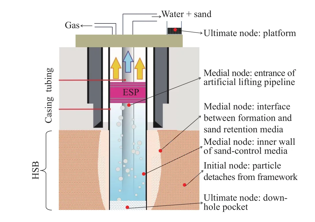
Fig. 1. SCS node set diagram.
Both the gas-dominated flow and water-dominated flow within the wellbore are pipe flows. Sand migration behaviors in these two flow conditions can be simulated or predicted using similar technologies. Thus, in SCS, both pipe flows can be classified into the same sub-system. Finally, SCS for clayey silt hydrate exploitation wells consists of three typical sub-systems: (1) Formation-related sub-systems; (2) sandcontrol media-related sub-systems; (3) borehole flow-related sub-systems.
According to the node setting results, key issues related to each sub-system are formation sanding behavior, down-hole sand retention optimization, and borehole sand-carrying flow assurance. Particle activation, particle migration, and particle production throughout the entire production system obey the principles of mass balance.
Hydrate reservoirs in the Shenhu area are characterized by low permeability, high shale content, and unconsolidated strata. Pore-filling hydrate reservoirs are widespread in a very heterogeneous and anisotropic way (Wu NY et al., 2017; Liu CL et al., 2017a). Thus, the main objectives of SCS for clayey silt hydrate exploitation wells in this area are to maintain formation stability and decrease the unfavorable effects caused by sand production. The predominant issue for the formation-related sub-system is particle detachment and migration behaviors under different pressure draw-down profiles. The predominant issue for the sand-control mediarelated sub-system is the optimization of moderate sandcontrol operation parameters, while that for the borehole flowrelated sub-system is to ensure the fulfillment of sandcarrying scenarios. In order to provide scientific evidence for production scheme decisions, all of these key issues will be analyzed intensively, together with the corresponding geological and operational risks for hydrate exploitation systems.
3. SCS sub-systems
3.1. Formation-related systems
During the process of depressurization or compulsive reservoir fluid extraction, the formation cementation degree maybe decreased, and the arrangement of particles might be changed. Particle detachment then occurs, followed by particle migration. This process is known as formation sanding. The formation sanding pattern and sanding behavior is the basis of down-hole sand retention optimization and wellbore sand-carrying flow assurance design, making them key for investigation in this study.
Compared with conventional natural gas reservoirs,hydrate reservoirs in the Shenhu area are shallower with even higher shale content (Liu CL et al., 2017b). The severe sanding tendency needs to be countered while extracting natural gas from hydrate-bearing sediment. Our previou work suggested that the sanding process for hydrate exploitation wells is controlled by geological factors, well completion factors, and production operation factors. An entire sanding process should meet the following three basic pre-conditions from a microscopic perspective:
(i) Fine particles should be detached from the framework or formation matrix, or they should at least not be combined.During the process of hydrate decomposition and production,the effective overburden stress applied to the framework will be increased, and the hydrate cementation effect on the formation matrix will decrease or even disappear. The increase in the decomposed water aggravates the liquidation of the formation matrix and shale content, which is particularly severe for montmorillonite.
The above hydro-mechanical coupling particle detachment is mainly controlled by the heterogeneity of the formation’s original cementing strength, hydrate saturation, particle size,permeability, pore-throat structure, and stress field, together with their dynamic evolution behaviors (Fig. 2). From the macroscopic sanding mechanism perspective, the microscopic factors controlling particle detachment mainly relate to the formation shearing failure, tensile failure, shale creeping, and hydrate decomposition. Schematic diagrams for typical particle detachment patterns are shown in Fig. 3.

Fig. 2. Controlling factors for particle detachment in hydrate reservoirs.
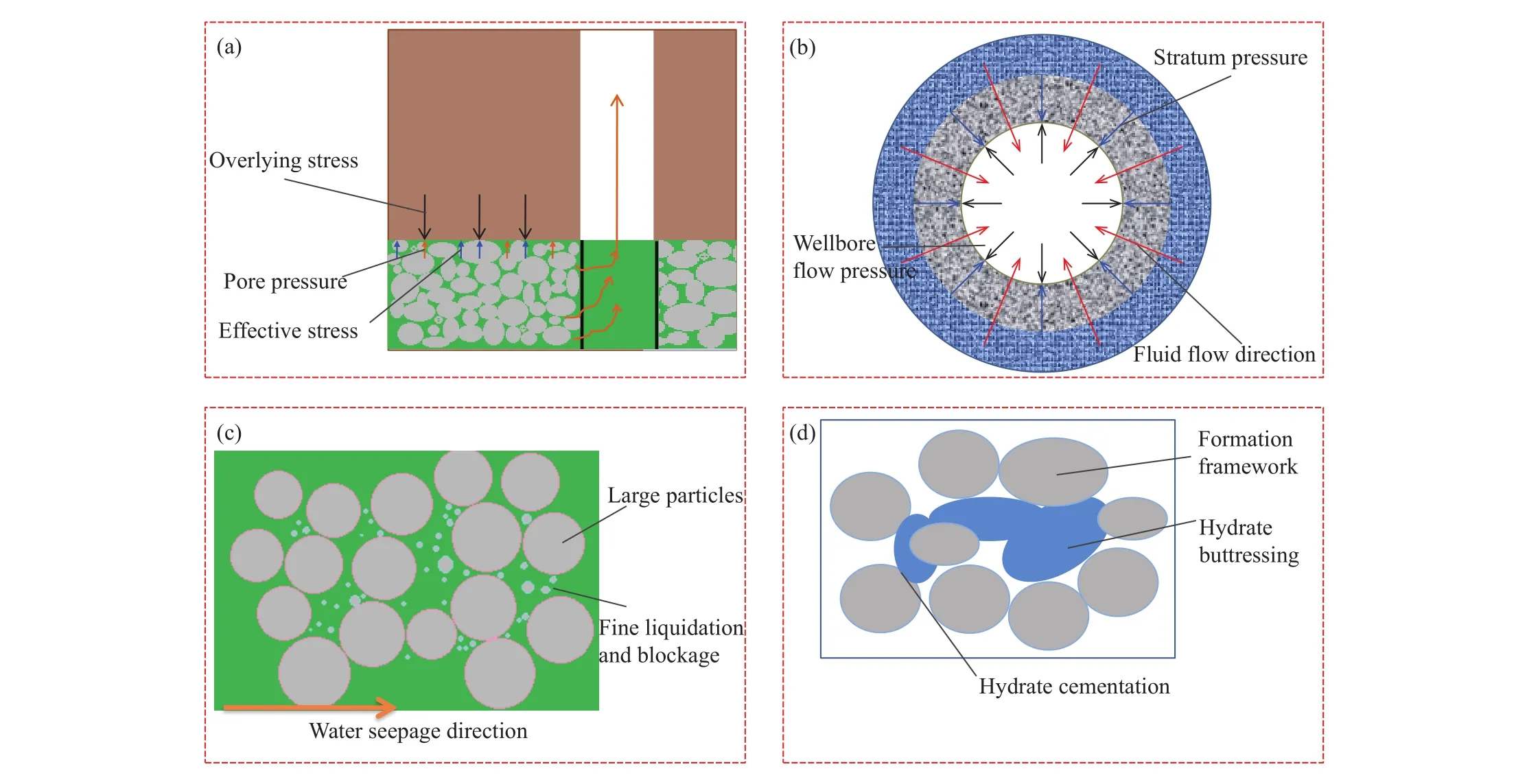
Fig. 3. Main particle detachment patterns in hydrate reservoirs. a-Shear failure because of stress change; b-tensile failure caused by fluid seepage; c-fine detachment caused by shale creeping; d-fine detachment because of hydrate decomposition.
(ii) A certain physical channel size is needed for particle transportation from in situ to the wellbore. At the pore scale,particle transportation morphologies in the formation mainly contain pore space liquefaction, with earthworm-like or continuous collapse (Fig. 4).

Fig. 4. Schematic of basic particle transportation morphologies.
When the hydrate is decomposed, water-gas multi-phase seepage can occur. Part of the pore-filled shale content may be suspended and activated. In other words, the pore-filled shale content is surrounded by fluid and seepage through porous media. The particle transportation morphology is defined as the pore space liquefaction phenomenon. Direct micro-manifestations of pore space liquefaction are changes in the pore diameter and fractal dimension. With the increase in production-pressure draw-down and hydrate-decomposing space, the seepage effect in a hydrate-decomposed area would increase correspondingly. A strong seepage effect leads to some high permeability zones in the formation, which can be defined as earthworm-like holes. Since the hydrate-bearing formations are always unconsolidated, earthworm-like holes evolve and expand in a timely manner. Finally, continuous collapse particle transportation morphology occurs, and the formation is faced with a vast sanding tendency.
In reality, no fixed or explicit boundaries exist among these particle transportation morphologies. Gradual changes and transitions occur according to the changes in the reservoir’s geological conditions and production operations.Analysis of the controlling factors and transition critical conditions for each of the particle transportation morphologies is the basis of sanding prediction for hydrate exploitation reservoirs.
(iii) Certain fluid flow conditions should be met in order to motivate and carry solid particles in porous media. Fluid flow velocity is the bottleneck of sand migration. Normally,the drag force applied by the water phase to pore-filled solid particles is much higher than that applied by the gas phase.Therefore, the main driving force for sand migration comes from water-phase seepage. Sufficient water replenishment to the sand migration area is the basis of particle migration.
As for the clayey silt hydrate-bearing reservoirs in the Shenhu area, clay minerals such as montmorillonite are widely distributed throughout the formation. Multiple effects of the clay minerals on particle migration within the formation should be considered. Firstly, hydration of montmorillonite leads to declension of the cementing strength. This can promote particle detachment from the framework or matrix, as was described in the first pre-condition. Secondly,montmorillonite has a strong water absorption capacity. This means that with more shale content in the formation, more decomposed water would be absorbed. The irreducible water saturation is higher than that in the formation without shale content. The relative water-phase permeability is lower because of gas expansion, and the drag force applied by the water phase is decreased. Thirdly, the montmorillonite expansion effect is vital because of the serious fluid-solid coupling effect that may be encountered for clayey silt hydrate reservoirs. Specifically, the expanded montmorillonite would block the original pore throat. Together with the effect of overburden stress, the original flexible pore would become sealed, and a large amount of decomposed water would become irreducible. Thus, under very high shale content conditions, the fluid-solid coupling effect would gather most of the decomposed water and also relieve the sand-production tendency.
According to these pre-conditions, the sand-production behavior analysis should include the following aspects:sanding controlling factor recognition, critical sanding pressure draw-down prediction (Liu HJ et al., 2017), sanding particle size, sanding rate, sanding area distribution radius in the formation. It should also be noted that the fluid-solid coupling effect will always be important for hydrate exploitation, particularly those composed of clayey silt.
Numerical simulation and laboratory experiments are two of the crucial ways of obtaining sanding behaviors. The discrete element method (DEM) can be introduced to simulate factors that affect the sanding process, such as the pressure draw-down, stress state, particle-to-particle bridge, hydraulic force, borehole instability, particle joint strength evolution,grain-size distribution, and pore roughness. In fact, even the finite element method (FEM) is incapable of detecting microscopical sanding mechanisms. It can, however, be used to model sand predictions and evaluate macroscopic sanding behaviors. Therefore, in order to detect sanding behaviors for clayey silt hydrate reservoirs, an ideal numerical sanding predictor should tightly couple both the DEM and FEM.
During the technical preparation process for China’s first marine hydrate exploitation test in the Shenhu area, a Tough+Hydrate+FLAC3D+PFC3D one-way coupling simulation model was adopted to simulate possible sanding behaviors, which already met some of the primary demands for field operation equipment selection and sand production management (Ning FL et al., 2017). In order to simulate the formation stress and strain evolution behaviors during the hydrate exploitation process, formation flow field parameters and temperature field data acquired from Tough+Hydrate were imported into FLAC3D via a specific interface (selfdeveloped Matlab code). Finally, all data obtained from Tough+Hydrate and FLAC3D were taken as boundary conditions for the sanding behavior simulation via PFC3D(Fig. 5).

Fig. 5. Numerical sanding simulation flow chart for clayey hydrate exploitation wells.
In PFC3D, an effective bonded corrosion model is introduced to model the effect of hydrate decomposition on formation mechanical properties. This is vital because the evolution behavior of mechanical properties with hydrate saturation has already been sufficiently studied by previous researchers (Hyodo M et al., 2014; Li YL et al., 2017b, 2018).The decomposition process of hydrate can be viewed as the process of decreasing the cohesion strength from a mechanical view. Additionally, in order to simulate the sanding rate under different levels of sand retention precision,a virtual mesh wall is equipped at the surface of the sanding frontier in the PFC3D granular flow model. Finally, the maximum sanding rate for site SHSC4, which is China’s first marine hydrate exploitation test site, is predicted to be less than 3.72 m3/d (the detailed simulation steps will be discussed in future work).
The superiority of this numerical simulation method is in the systematic balance among the gas productivity ratio,formation stability, and sanding rate management. The proper sanding rate prediction is based on the accuracy of the predicted fluid flow field and strength evaluation. While a bilateral coupling simulation interface has been established between Tough+Hydrate and FLAC3D, only a one-way coupling interface was modeled between Tough+Hydrate+FLAC3D and PFC3D. Thus, the sand migration field was considered via one-way coupling. In future work, more emphasis will be put on a bilateral coupling simulation interface between the simulators. However, a general bilateral coupling simulation would cause a vast increase in the calculation time, so the simulation efficiency should also be considered.
Laboratory experiments are another direct and effective way to obtain sand-production parameters. A series of sandproduction simulation apparatuses has been established by the Qingdao Institute of Marine Geology (Li YL et al., 2017c,2017d; Liu CL et al., 2016), which has a novel, large-size,experimental simulation system with the following functions:(1) Gas hydrate preparation according to marine hydrate formation conditions; (2) real-time monitoring gas hydrate distribution in sediment; (3) simulation of the wellbore drilling process; (4) monitoring the sanding rate, sanding flux,and sanding size during the depressurization exploitation for gas hydrate.
This experimental system consists of a high-pressure vessel, drilling simulation module, liquid supply module, gas supply module, confining pressure loading module, backpressure control module, output separation module,temperature control module, data acquisition module, and operational platform. The size of the high-pressure vessel isΦ750 mm×1180 mm with a volume of 521 L (Fig. 6). The working temperature is -20°C to 50°C, and the design pressure is 35 MPa. The size of the confining pressure neoprene sleeve isΦ600 mm×1145 mm, and the inner size for the sediment sample isΦ600 mm×1000 mm with a volume of 282.6 L. An electrical resistance tomography system with 320 electrodes is used for detecting the distribution of gas hydrate in the sediment. A novel drilling machine has been installed onto the high-pressure vessel, with which the sand-control pipe (sand screen) can be drilled inside the sediment at a depth of 900 mm with a drilling speed of 100 mm/min after gas hydrate formation. Once the drilling process is finished, a gas hydrate-production test is carried out by depressurization or heat stimulation to produce gas, water,and sand through the output separation module for quantitative analysis.

Fig. 6. Picture of the 3D NGH exploitation simulation system.
Our particular interest for this experimental system is to simulate both the drilling and exploitation process of methane hydrate in sediment and monitor the variation in parameters during this process. Detailed sanding monitoring experimental data will be outlined independently and therefore will not be repeated here.
3.2. Down-hole sand-control related sub-systems
The main operational factor affecting the formation sanding rate is pressure draw-down, while that for the downhole sand-production rate is sand-control operational parameters, which mainly includes the sand-control method and corresponding operational parameters. In hydrate exploitation wells, the main purpose for down-hole sandcontrol is to maintain the down-hole sand-production rate at a controllable level.
Sand-control media is the only flow channel from formation to wellbore and is the crucial barrier that mitigates the disastrous sand influx into the wellbore. Commonly used sand-control media include screens and packing layers. The basic theory for down-hole sand-control in hydrate exploitation wells is similar to that in conventional oil and gas wells, but it varies in purpose and in the parameter optimization method. In conventional oil and gas wells, the fundamental objective for down-hole sand management is to block particles from flowing into the wellbore. On the contrary, in clayey silt hydrate exploitation wells, the fundamental objective for down-hole sand-control is to eliminate most of the fine particles proactively and only block relatively large particles such as foraminifera shells.
Field exploitation trials are limited for verifying the validity of a specific sand-control method, almost all field trials have proven that sand-control optimization based on conventional sand retention concepts is not suitable for hydrate exploitation wells, especially for clayey silt hydrate reservoirs (Liu CL et al., 2017c). Historical down-hole sandcontrol methods and their corresponding results are summarized in Table 1.

Table 1. Historical down-hole sand-control methods and corresponding results in hydrate exploitation wells.
Coated sand was used on Geoform, a chemicalmechanical compound screen, to form a relatively fixed packing layer with high porosity and relatively high strength.The main purpose of a Geoform screen is to overcome gravel creeping and settlement problems caused by the open-hole gravel packing (OHGP) method (Fig. 7). However, because coated gravel is absolutely fixed outside the baseline, minor shale blockages may lead to vast integral blockages of the screen. With the exception of Japan’s 2017 hydrate exploitation trial, which used Geoform, almost all hydrate exploitation tests have chosen pure mechanical sand-control media as their first choice for down-hole sand-control.

Fig. 7. Schematic of massive gravel creeping and settlement problems caused by OHGP.
To overcome the negative factors in clayey hydrate exploitation wells, a novel pre-packed screen is provided.This kind of pure mechanical pre-packed screen is made of a baseline, packing layer, and outer protector. The packing layer can have minor creeping in the limited space defined by the outer protector and baseline. This kind of minor creeping is essential to keep minor shale blockage from evolving into vast integral blockages of the screen. This effect can be defined as the “self-blockage removing” effect. Otherwise, a pure mechanical pre-packed screen could overcome massive gravel creeping and settlement problems in the same manner as Geoform.
Sand retention precision is the key parameter for downhole sand-control optimization. The main sand-control media are screen mesh and gravel packing layers. Thus, the essence of sand retention precision optimization is selecting the proper screen mesh throat size or gravel size. Relatively lower sand retention precision is good for decreasing skin factors and improving the gas extraction efficiency, but it will lead to vast sand influx into the wellbore. Too much sand influx into the wellbore creates significant pressure for wellbore sand carrying. On the contrary, relatively high sand retention precision is good for mitigating the sand influx into the wellbore, but it will lead to depression of the gas extraction efficiency. Under conditions of high shale content, minor shale blockages will easily evolve into integral blockages of sand retention media.
Therefore, to maintain formation stability and gas extraction efficiency, the following principles should be considered when selecting the proper sand retention precision.Firstly, proper sand retention precision should ensure all fine particles can pass through sand-control media to avoid shale blockages and to maintain gas extraction efficiency. Secondly,proper sand retention precision should block coarse particles to maintain formation stability.
Since all formation sediments consist of shale content and sand content, sand content could be divided into two sections:relatively fine particles and relatively coarse particles. Proper sand retention precision should eliminate both the shale content and relatively fine sand particles but maintain the relatively coarse particles at the same time. This kind of sand retention precision can be defined as the holding coarse expelling fine particles (HCEFP) method. A detailed optimization flow chart is depicted in Fig. 8. It should be noted that coarse and fine sand are relative concepts in the HCEFP method, which differs from those absolute grain-size definitions in logical sediment areas.

Fig. 8. Flow chart of sand retention precision optimization based on the HCEFP method.
Based on the HCEFP method, proper gravel sizing was selected for SHSC4. The recommended gravel size for site SHSC4 ranges from 215-360 μm. It can be seen from Fig. 8 that the particle size distribution (PSD) analysis is the basis of the down-hole sand-control operation optimization. In the conventional oil and gas industry, original PSD curves are always used for sand retention precision selection. Only part of the formation sand has the possibility of migrating from the formation into the wellbore; that is what needs to be managed or controlled by sand-control media. Therefore, optimization results based on primary core PSD data may have some deviation from those needed. In another words, the meticulous depiction of the possible formation sanding parameters is the basis of down-hole sand-control. On the contrary, the downhole sand-control parameter conditions would also affect the sanding behaviors within the formation. This kind of bilateral coupling effect is difficult to distinguish and should be researched more in the future.
3.3. Borehole flow-related sub-systems
Borehole sand-carrying flow assurance technologies for hydrate exploitation wells are similar to those in conventional oil and gas wells, except for the fact that they should be considered a sub-system of SCS in hydrate exploitation wells.Borehole sand-carrying flow sub-systems should be consistent with the two aforementioned sub-systems. Platform sand sinks or wellbore pockets are the end of produced sand.According to the mass conservation law, the sum of sand that settled down into the pocket and was captured by platform sand sinks should be equal to that passed through sand-control media.
As for the SHSC4 hydrate exploitation well, the electrical submersible pump (ESP) was used as the artificial lift equipment. A gas-liquid separator is installed at the bottom of the ESP inlet. Thus, gas would be separated and flow out to the wellhead via the annulus between the tubing and casing,while the water-solid mixture would be lifted through tubing.In some extreme conditions, the separator cannot separate the gas completely. Therefore, the ESP separator can be considered a sub-node to divide the borehole sand-carrying sub-system into two stages. The first stage is characterized by a flow mode in which gas motivates water and water carries sand. The second stage is pure water, sand-carrying flow, or mixed-fluid sand-carrying flow under a high water-gas ratio.The first stage mainly affects the borehole pocket sand settling rate and ESP life span. The optimization purpose of the second sand-carrying stage is to avoid sand blockage risks and prolong the sand-washing cycle. The main problems related to the borehole sand-carrying process in hydrate exploitation wells are shown in Fig. 9.

Fig. 9. Main problems within borehole flow-related sub-systems.
Among all the problems shown in Fig. 9, the first stage is closely related to the two aforementioned sub-systems. Thus,the destination of the sand-carrying behavior analysis for the first stage is to establish an information visualized simulator(IVS) for the sand settling prediction. The IVS prediction is essential for supplying operational warnings for down-hole sand-control optimization and even up to real-time pressure draw-down adjustment. The ultimate goal of the sandcarrying behavior analysis for the second stage is to supply a significant basis for the wellbore fluid supplementation and artificial lift designation.
Numerical simulation has become one of the popular ways to analyze borehole sand-carrying trends, because both sandcarrying problems and hydrate reformation problems may be encountered simultaneously in hydrate exploitation wells. The combination of particle flow code and multi-phase flow simulation code is essential to analyze typical sand-carrying behavior, together with hydrate reformation problems.Typical simulation results by combining PFC3D and TransAt are shown in Fig. 10. Based on the above simulation, the maximum wellbore blockage risk position was estimated to be located at the annulus between the ESP upper-packer and choke line for SHSC4, which is marked as “A” in Fig. 9. The wellbore blockage risk position assessment took into consideration both the sand settling risk and hydrate reformation risk. Therefore, a supplemental line was added to inject brine at SHSC4 during gas production. The outlet of the so-called supplemental line is located at the “A” area denoted in Fig. 9. Injected brine is used for both sand carrying and avoiding hydrate reformation at this location.

Fig. 10. Diagram of the sand-carrying flow simulation in conjunction with PFC3D and TransAt.
Under down-hole sand-control conditions, the borehole sand-carrying flow assurance analysis is based on accurate fluid production predictions and sanding predictions. On the contrary, the borehole sand-carrying capacity should be considered during the process of down-hole sand-control optimization and pressure draw-down scheme optimization.
4. Conclusions
(i) Sand production is unavoidable for hydrate exploitation wells, especially for clayey silt hydrate reservoirs. Different sub-systems related to sand migration work in an interactive and bilateral coupling way. To deal with sand-production problems for clayey silt hydrate reservoirs, a systematic solution should be applied to maintain formation stability and prolong the gas production cycle. NSAM is introduced in this paper for SCS analysis.
(ii) Formation sanding behaviors, down-hole sand-control optimization, and borehole sand-carrying technologies are key constitutive requirements for SCS. The sub-systems are closely connected via bilateral coupling. Coordination of the above key constitutive requirements is the basis of maintaining formation stability and prolonging the gas production cycle.
(iii) For further hydrate exploitation, contradictory mitigation between sand production and operational systems should be considered preferentially. Therefore, the present SCS is only suitable for conventional hydrate exploitation methods, such as depressurization methods or compulsive reservoir fluid extraction methods. Some novel and efficient gas extraction methods are needed to completely solve the contradictions caused by sand production.
Acknowledgement
This research was supported by the National Natural Science Foundation of China (41606078); National Key Research and Development Plan (2017YFC0307600);Qingdao National Laboratory for Marine Science and Technology (QNLM2016ORP0207, QNLM2016ORP0203)and Marine Geological Survey Program (DD20190231;DD20190221). These financial supports are gratefully acknowledged. The authors are grateful to the China Geological Survey for promoting marine hydrate exploitation tests in clayey silt hydrate reservoirs, which provided most of the motivation for this research. Members from the hydrate exploitation directorate at GMGS are also thankful for the excellent suggestions about this work. The authors are also grateful to experts and anonymous reviewers and Dr. Yan Yang for their valuable suggestions and comments on the manuscript.

- China Geology的其它文章
- Characteristics and evaluation of Mesozoic source rocks in the southeastern East China Sea continental shelf
- Two types of uranium mineralization in Gulcheru quartzite: Fracture-controlled in Ambakapalle area and litho-controlled in Tummalapalle area, Cuddapah Basin, Andhra Pradesh, India
- Redefinition of Early Mesoproterozoic (1800-1600 Ma) stratigraphy in the northern Kongling area, China: The nucleus of Yangtze Craton and its tectonic significance
- Comparison of detrital mineral compositions between stream sediments of the Yangtze River (Changjiang) and the Yellow River (Huanghe) and their provenance implication
- Stretching correction for amplitude-preserving vector wavefield reverse-time migration
- Analysis of formation and slope stability in Caofeidian Channel in Bohai Bay