
Dynamics Modeling and Stability Analysis of Tilt Wing Unmanned Aerial Vehicle During Transition
2019-06-12 01:23YonghongZhangYunfeiDengYunpingLiuandLihuaWang
Computers Materials&Continua 2019年6期
Yonghong Zhang ,Yunfei DengYunping Liu and Lihua Wang
Abstract:In the transition mode of quad tilt wing-unmanned aerial vehicle (QTW-UAV),the system stability of UAV will change with the tilt angle changes,which will cause serious head drop down.Meanwhile,with the complex air flow and other disturbances,the system is prone to side bias,frying,stall and other kinetic stability problems,hence the system stability analysis has become an urgent problem to be solved.To solve the stability problem,we need the quantitative criteria of system stability and effective tool of stability analysis,and can improve the stability of the motion control by optimizing the structural parameters of the aircraft.Therefore,based on the design of the mechanical structure,the quantitative relationship between the structure parameters of the aerial vehicle and kinetic stability of the system transition mode is established by the Lyapunov exponent method.In this paper,the dynamic modeling of the position and attitude angle is carried out and the stability of the system is analyzed by Lyapunov exponent,the results show that changing the mechanical structure of the system can improve the flight stability for the system transition mode and lay a theoretical foundation for the system stability analysis.Compared with the Lyapunov direct method,this method can be construct easily,has a simple calculation process and so on.We improve the flight stability by optimizing the structure and the experiment confirms that expanding area can enhance flight stability within limits.
Keywords:QTW-UAV,transition,stability,dynamics model,lyapunov exponent.
1 Introduction
QTW-UAV combines the advantages of fixed-wing aircraft and helicopters,featuring fast flight and vertical takeoff and landing.But when the wing tilt,wing lift,forward speed and angle of attack will change with the wing tilt angle changes,and the propeller lift and thrust will also change.So when these factors are coupled to the original complex system [Oosedo,Abiko,Narasaki et al.(2016)],aerial vehicle is prone to side bias,frying,stall and other kinetic stability problems.Because of the complex airflow,the aerodynamic environment is very complex [Liu,Li and Wang (2011)],and the overall dynamic structural changes with the tilt angle changes,so the transition mode is also the most unstable flight mode of QTW-UAV,and because of the high cost of UAV and its carrying equipment,the accident is more dangerous to the ground.Therefore,in addition to the design of controller at the transition stage of the QTW-UAV,the study of its flight stability and reliability is a very challenging task.
The stability analysis of the nonlinear system is critical to the safety of the engineering system.Kinetic stability is the nature of the motion trajectory that deviates from its trajectory after the system is under external disturbance [Kumon,Katupitiya and Mizumoto (2011)],and Lyapunov theorem of stability is very effective for such system analysis.However,due to the lack of a constructive approach to derive Lyapunov function,resulting in the extremely limited application of Lyapunov stability.For example,in the study of the stability of the biped robot,it is found that the stability of the balanced stand of the biped robot is affected by the limitation between the foot and the ground,and the Lyapunov equation is a very effective method for the stability analysis.However,due to the complexity of the dynamic equation,difficult constructing of Lyapunov function and other issues,it is difficult to obtain a Lyapunov equation from the high non-linear biped system [Wu,Sepehri and Thornton-Trump (1998)].In addition to Lyapunov function,Lyapunov exponent can also show the stability of the system [Wolf,Swift,Swinney et al.(1985);Alligood,Sauer and Yorke (1997);Williams (1997)],which is defined as the divergence of the orbit in the vicinity of the state space or the average exponential rate of convergence,which can quantitatively describe the degree of divergence or convergence of the two orbits of the initial value and original value in the exponential form after the system is being disturbed.The main advantage of Lyapunov exponent is that the calculation method is simple and feasible,making the complex nonlinear system stability analysis possible.
The calculation of the values of Lyapunov exponent usually uses mathematical model or time series [Yang,Wu and Zhang (2012)],and the calculated Lyapunov exponent can describe the stability of the system.The method based on mathematical model has been applied,and in addition to being widely used in the diagnosis of chaotic systems,it is also used in the stability analysis of complex nonlinear systems.Sekhavat et al.used the concept of Lyapunov exponent to analyze the stability of nonlinear dynamical systems,demonstrating that this method is constructive and robust [Sekhavat,Sepehri and Wu (2004)].And Wu Qiong has studied the stability of biped robot in motion via the Lyapunov exponent method [Yang and Wu (2006)],Ding Well also applied the Lyapunov exponent method in the field of bio-mechanics to study the kinetic stability of human upper body during walking [Dingwell and Marin (2006)].Thus,Lyapunov exponent can quantitatively describe the multivariable,highly coupled,under-actuated nonlinear system,and can establish a quantitative relationship with the system kinetic stability,providing an effective solution for similar problems.
In this paper,the challenge of QTW-UAV stability research is the lack of an effective tool for quantitative criteria and stability analysis of system stability,and QTW-UAV stability control and stability analysis are still in the research stage.
In addition to the optimization of the controller for QTW-UAV kinetic stability,the kinetic properties of the entire system can be affected by changing the mechanical structure parameters [Chevallereau (2002),Mokhtari and Benallegue (2004)].Therefore,optimization of aerial vehicle mechanical structure parameters in the transition mode of QTW-UAV is important for improving the kinetic stability of system specific at a specific tilt angle.Lyapunov exponent is an important method that can be used to quantify the kinetic stability of QTW-UAV in transition mode.
The rest of the article is organized as follows.The second part establishes a dynamic model based on Newtonian Euler equations.The third part is based on the model established in the second part,based on the Lyapunov exponent method to establish the quantitative relationship between system structural parameters and motion stability.The fourth part is the simulation of the influence of stability after changing the wing structural parameters based on the Lyapunov exponent method.The fifth part is devoted to the experiment to verify the impact on the flight stability after changing the wing structural parameters.The conclusion is in the sixth part.
2 Dynamics modeling
The figure of QTW-UAV structure shown in Fig.1 is used as the object of study,defining the ground coordinate system asW(Xw,Yw,Zw),fuselage coordinate system asB(Xb,Yb,Zb)and rotor wing coordinate system asT(Xt,Yt,Zt).Fuselage coordinate system is located in the centroid position of the system.Generalized coordinates(x,y,z,p,q,r)are the state variables,and each attitude angle satisfies the yaw angle(-π<ψ<π),the pitch angle (-π/2<θ<π/2)and the roll angle ( -π/ 2<φ<π/2).

Figure 1:Coordinate diagram
To make the whole modeling process simple,the following assumptions are made:
·The components of aerial vehicle use rigid body.
·The center of mass is the same.
·The interaction between left and right blades and their effect on aerodynamic forces are ignored.
The whole system dynamics equation is obtained according to the Newton-Euler equation:

where,Ω=[p,q,r]Trepresents the angular velocity vector,V=[vx,vy,vz]Trepresents the velocity vector.
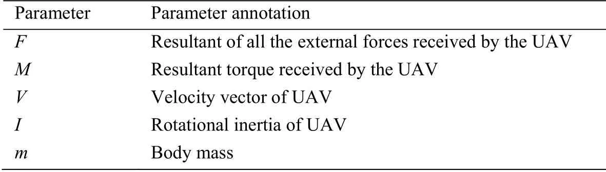
Table 1:Parameter specification
2.1 The force and torque produced by the main rotor wing
UAV has a total of four rotor wings,set the tensile force of a rotor wing asFr,j,j denotes the j-th rotor wing.As shown in Fig.2,set the wing tilt angle asαj.Owinis in the plane of the body coordinate systemOwXwYw,hjindicates the distance from the center of the rotor wing toOwin.We can calculate the component force of rotor wing tension along the body coordinate system axesXbandZb:

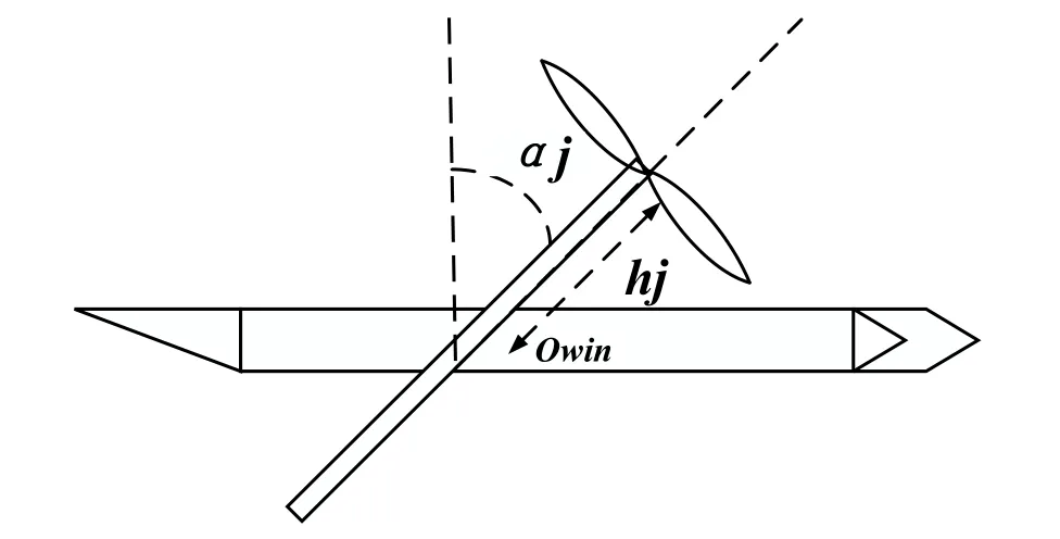
Figure 2:Tilted side view of UAV wing
Fig.2 shows the top view of the wing when it tilts α°.When the wing tilts α°,the arm of force of the propeller can be expressed as r1,r2,r3,r4.
Since the distribution of the tilted wing is symmetrical and the height of each propeller is the same,then h1=h2=h3=h4=h.The tilt angle of both sides of the same wing should be the same.That is,α1=α2=α3=α4=α.The torque generated by the rotor wing tensile force is the multiplication cross of tensile force vector and the force arm vector:

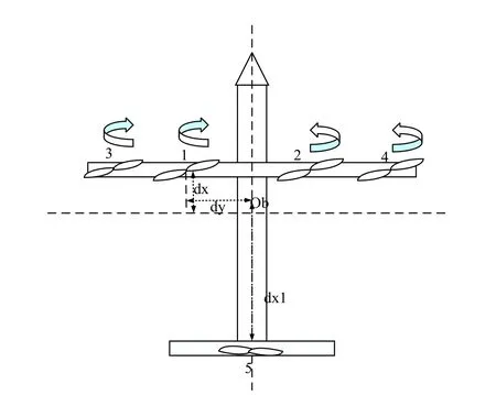
Figure 3:Top view of aerial vehicle
2.2 The force and torque produced by the main rotor wing
When the wing is tilted to a certain angle and the UAV is flying at a higher speed,the lift and resistance of the wing cannot be ignored.
The wing lift FL and wing resistance FD in the body coordinate can be expressed as:
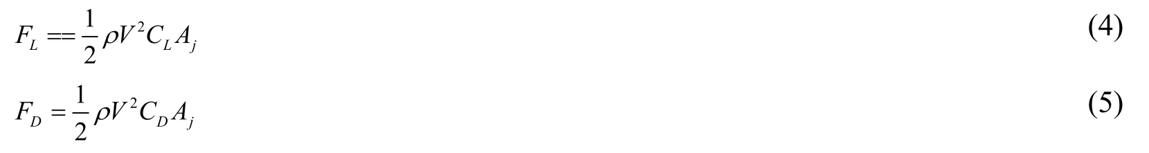
Where,CL and CD are the lift and resistance coefficients of the wing,Ajis the wing area.Supposing that the center of wing lift and resistance is located in the middle of the wing and the wing is deflected around the center axis,the arm of force can be expressed as lj.Torque produced by the wing:
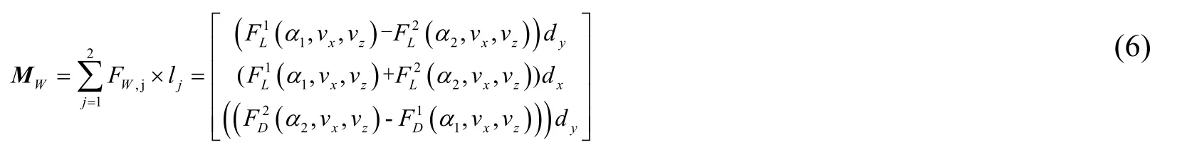
Since α1=α2,A1=A2,and the value of resistance and lift is negative in the body coordinate system,so FL1,=FL2=FL,FD1=FD2,=FD,simplified as:
2.3 The force and torque produced by the tail rotor wing
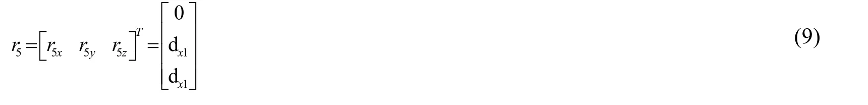
UAV has one tail only,which can turn around.Denote the rotor wing tensile force as F5,as shown in Fig.4.O1 is in the plane of the body coordinate systemh5 is the distance from the rotor wing center to O1,and γ is the rotation angle.We can calculate the component of rotor wing tensile force along axisbZof the body axis system:
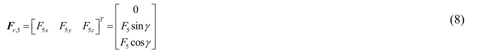
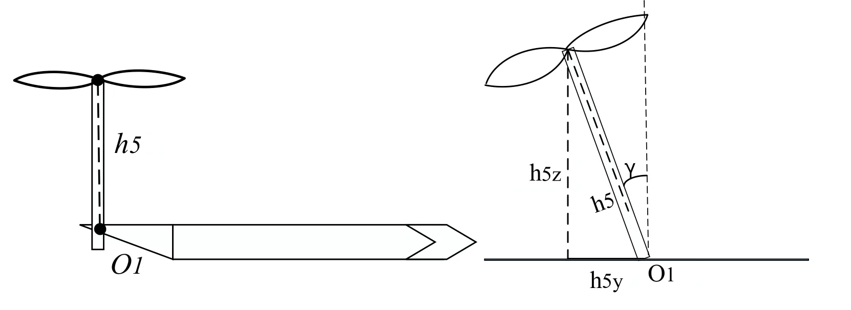
Figure 4:Right view and rear view of tail rotor wing
UAV tail is symmetrically distributed above fuselage.Ob is the center of mass of the UAV,dx1 is the distance from the rotor wing center to the plane of the body coordinate systemOwYbZb.Since the tail rotor wing is on the plane of body axis systemOwYbZb,dyis 0,which can be ignored.The arm of force of the rotor wing tensile force can be expressed as r5.
Since the distribution of the tilted wing is symmetrical and the height of each propeller is the same,then h1=h2=h3=h4=h5=h.The torque generated by the tail rotor wing tensile force is the multiplication cross of tensile force vector and the force arm vector:
2.4 The force and torque produced by the tail wing
Wing lift FL5 and wing resistance FD5 in the body coordinates can be expressed as F5D,F5L.
2.5 Gravity and fuselage resistance
The gravity of fuselage acts on the center of mass,and it does not produce torques.
The tensile force and torque of UAV body are summarized in Tab.2:

Table 2:Summary of tensile force and corresponding torques
2.6 Dynamics modeling of tilt wing
Kinetic model in transitional flight mode.Consolidate the above equations and equations,the force is unified to the ground coordinates,through simplifying results ,obtaining the linear motion equation of aerial vehicle:
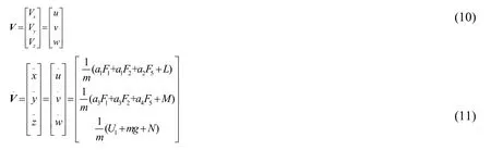
Where,Frx,FryandFrzare the components of the acting force of propeller and wing along the X axis,the Y axis and the Z axis under the body axis system.Since the tilt angle α is the same,the wing area is the same,so the lift and resistance of four rotor wings are the same:

Xbis the wing lift,Xbis the tail lift
Xbis the wing resistance,Xbis the tail resistance
Decomposed into the equation rotating the three axes of body axis system
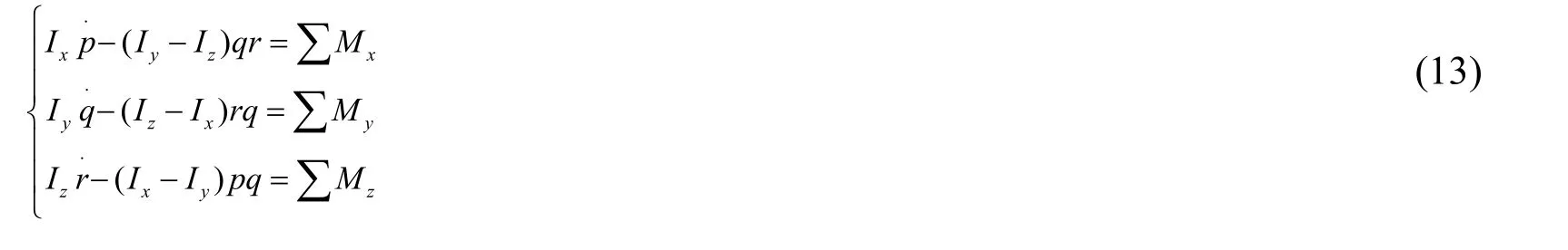
Where,Ix,Iy,Izare the axial inertia torques of the axisXb,axisYband axisZbalong the body axis system,respectively.The external torque is:

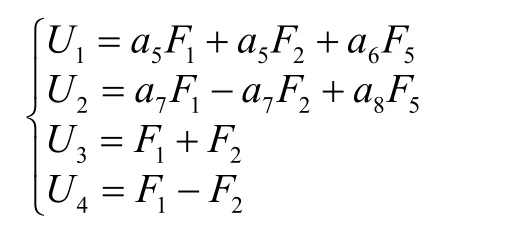
After the torque is unified into the body axis system,the angle kinetic equation of the tilt wing is obtained as follows:
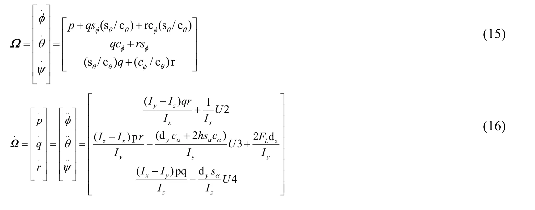
U1is the variable of height control,U2is the variable of roll angle,U3is the variable of pitch angle,U4is the variable of drift angle.
Convert the formulas (10)-(16)into the system state equation form,see formula (17):

Where,X=[q p]T=(φ,θ,ψ,x,y,z,p,q,r,u,v,w)T.
3 Calculation of lyapunov exponent
In this paper,the Lyapunov exponent standard is used to describe the chaotic behavior of the nonlinear state equation.An attraction point is regarded as x,an adjacent attraction point is regarded as x+ɛ,x and x+ɛ are iterated n times by mapping function.And then find the absolute value of these two results,see the following:

If this behavior is chaotic,this distance is n times the exponential growth,so

can be expressed as

λis the trajectory of the Lyapunov exponent.Following the chain rule of differentials,the derivative of f(n)can be described as n products derived from f(x)at successive trajectories x0,x1,x2...xn.Therefore,the definition of Lyapunov exponent can be more intuitively expressed as:

The equation can also be expressed as

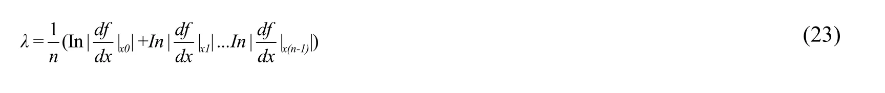
Take n->∞,Lyapunov exponent formula can be expressed as:

λ< 0,the track is a neutral fixed point.
λ=0,the track is attracted to a stable periodic orbit.
λ> 0,the track is unstable and chaos.
Lyapunov exponent is the average exponential rate at which the initial and the original values of the system are converged or diverged over time.Lyapunov exponent specific analysis method is:phase volume contracts in the direction where Lyapunov exponent is less than 0,UAV system motion is stable and is not sensitive to the initial conditions of the system,otherwise unstable [Abdulwahab and Atiyah (2013)].
Lyapunov exponent is calculated by formula (19),the calculation process is shown in Fig.5:


Figure 5:Calculation process of Lyapunov exponent
For the calculation of Lyapunov exponents λ1,λ2,…,λ6,take time T=0.1 and the number of iterations K=50.For the kth iteration (k=1,2,…,K),the initial conditions of matrix variational equation formula (19)is {u1(k-1),u2(k-1),…,u6(k-1)},obtain the vector {w1(k-1),w2(k-1),…,w6(k-1)} after Ts integration,then conduct the GramSchm orthogonalization,and the vector is converted to {v1(k-1),v2(k-1),…,v6(k-1)}.Vector {u1k,u2k,…,u6k} is obtained through normalization.This process is repeated until the Lyapunov exponent reaches the maximum number of iterations K,and the resulting indexes λ1,λ2,…,λ6 form Lyapunov exponential spectrum [Liu,Li,Wang et al.(2015)].
Thus from formula (19),we can see when the structure of the system is determined,the size of the Lyapunov exponent is determined by the Jacobian matrix |df/dX| of the function f(X)at Xi.Formula (19)can deduce the main structural parameters (see Tab.2)that affect the size of Lyapunov exponent.There is mass center vector r,system mass m,system inertia Ix,Iy,Iz,and wing area Ai.According to the above analysis,we can improve the stability of the system by changing the center of mass vector,system quality,system inertia and wing area Ai that affect the whole system dynamics.
4 Simulation analysis of stability at transition mode stage
Before the simulation,the dynamics modeling of vertical take-off and transition mode of QTW-UAV were made by Mathmatica software.Then the Lyapunov exponent method is used to calculate the Lyapunov exponent while by using the obtained nonlinear mathematical model.
4.1 Parameter determination
According to the above analysis,it is necessary to obtain the following parameters:m,g,α,dx,dy,dz,h,Ai,A5,ρ,Ix,Iy,Iz,Jp,CD,CL,Kr and Kq for building a kinetic model of QTW-UAV.The overall structural parameters of QTW-UAV are shown in Tab.3.
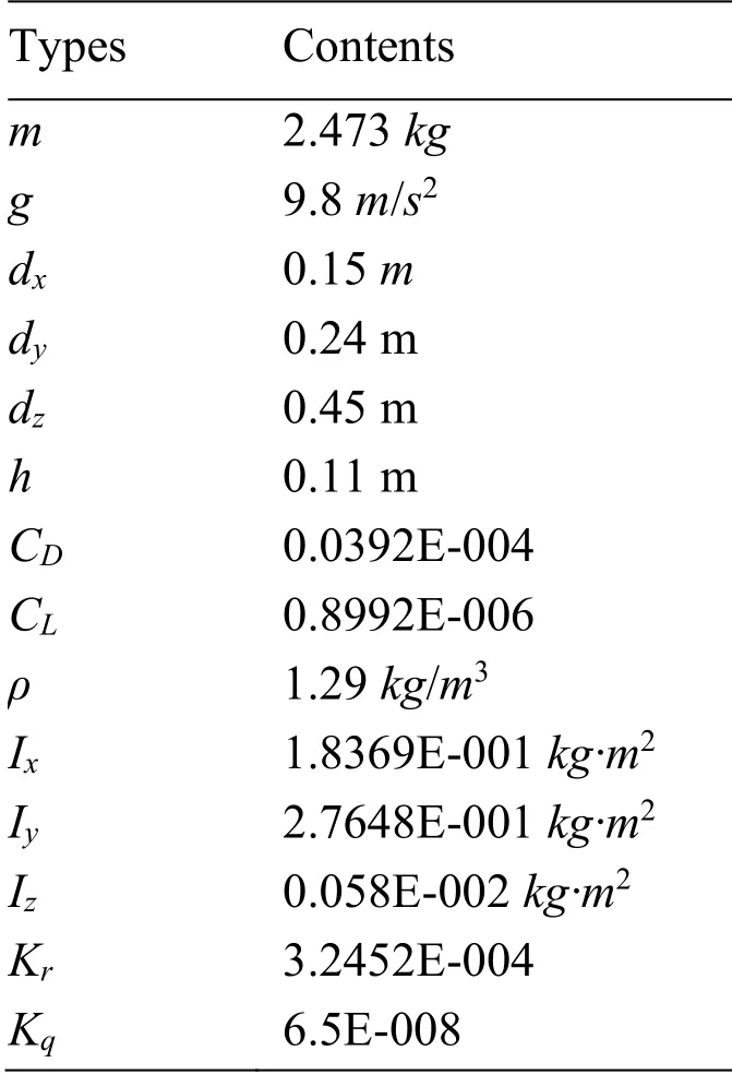
Table 3:Overall structure parameters of the system
Where,wing tilt angle α is 30°,parameters can be measured directly are the system quality m=2.473 Kg,center of mass vector dx=0.225 m,rotor wing radius R=0.12 m.Through the search tool we can get the local gravity acceleration g=9.8 m/s2,air density ρ=1.29 kg/m3.Other parameters need to be obtained by experiment,Wing area measurement can use the four-point control thrice Bezier curve to measure and draw the wing profile and wing stereo diagram.
the measurement method of wing area:sd is the half-area of the cross section of the wing,ld is the half-perimeter of the cross section of the wing,Calculation of wing surface area:S=2 sd+20 ld.
The method of calculating the half-perimeter of the cross section of the wing by successive trapezoidal approximation segmentation is:
The method of calculating the half- area of the cross section of the wing by successive trapezoidal approximation segmentation is:

We take four points from the plane:P0(0,0),P1(0.01,1),P2(1,2),P3(20,0),and the coordinate parameter equation of the thrice Bezier curve can be obtained.Through the above formula,we can use matlab for command operation to draw the wing profile and wing stereo diagram,and obtain the wing area.
Experiment results:

Figure 6:Wing profile
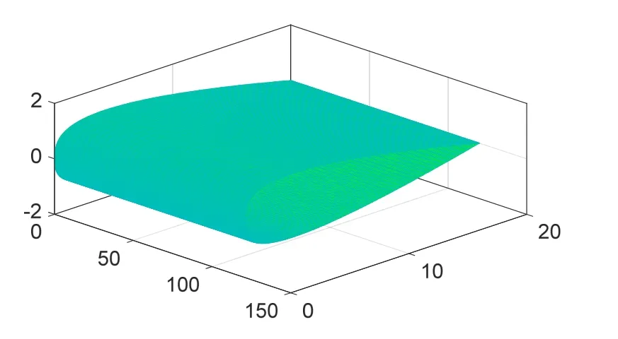
Figure 7:Wing stereo diagram
After selecting the four points P0 (0,0),P1(0.01,1),P2(1,2),P3(10,0),measure and draw the wing profile and wing stereo diagram:

Figure 8:Wing profile

Figure 9:Wing stereo diagram

Table 4:Calculation results of wing surface area
4.2 Simulation results
Fig.10 to Fig.11 show the simulation in details.We established the mathematical model,then carrying on the system attitude Lyapunov exponent simulation by mathematics and stability quantitative analysis,when the speed of system attitude Lyapunov exponent tending to 0 is faster,indicating the flight stability is higher.
The purpose of the experiment in Fig.10 is to verify whether the flight stability of the QTW-UAV can be improved by changing the wing area.It can be seen from Fig.11:When QTW-UAV is at transition mode stage,and the wing is tilted 30°,within a certain range,the other structural parameters remain unchanged as shown in Tab.3,only change the wing area size,then the wing area A is increased by 1.05 times and 2 times.After the area is increased by 1.05 times,the speed of system Lyapunov exponential spectrum converging to 0 is faster than that of before the wing area increase,i.e.,the stability of the QTW-UAV with the wing area increased is improved.After the area is increased by 2 times,the speed of system Lyapunov exponential spectrum converging to 0 is decreased,and the system becomes unstable.The actual phenomenon is:by increasing the wing area,you can increase the system lift,improve stability,but also increase the resistance,so only in a certain range,the appropriate increase in wing area can improve the stability of the system.
The simulation in Fig.11 compares the Lyapunov exponents ofψattitude angle after the wing area of each tilt angle is increased 1.05 times when UAV wing is tilted by 0°,15°,30°,45°,60°,90°.It can be seen that when the wing is tilted by 0° and 15°,the increase of the speed of system Lyapunov exponential converging to 0 is not obvious.In case of 30°,45°,60°,90°,after increasing the area,the speed ofψattitude angle Lyapunov exponential converging to 0 is at a significantly faster speed.This shows that when wing is tilted between 0° and 15°,the increase of wing area does not greatly improve the stability of the system,and in the case of greater than 30°,the increase of area can improve the stability of the system.The actual phenomenon is that when the wing is tilted from 0° to 15°,the main lift of the UAV is provided by the rotor wing tensile force,and the effect of the wing lift on the UAV lift is increasing after more than 30°.
At the transition mode stage of QTW-UAV,wing is tilted by 30°,other mechanical structure parameters remain unchanged,the contrast of simulation results after increasing wing area A:
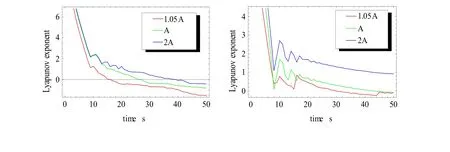
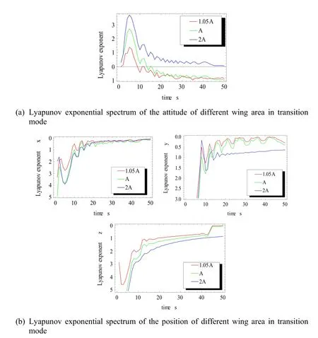
Figure 10:a and b are Lyapunov exponential spectrum of the position and attitude of different wing area in transition mode
In the transition mode stage of QTW-UAV,increase the wing area A when wing is tilted by 0°,15°,30°,45°,60° and 90°,the contrast of simulation results of attitude angles’ Lyapunov exponents:
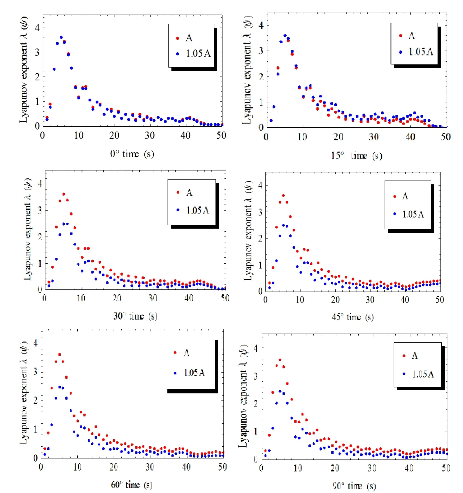
Figure 11:Lyapunov exponential spectrum of ψ attitude angle of different wing area of the tilt angles in transition mode
5 Verification of structural optimization experiment
We intend to optimize the structure of airframe to improve the stability of Tilt Wing Unmanned Aerial Vehicle.Taking QTW-UAV as the research object,we increase the wing area 1.05 times and verify flight experiments.Also we confirm the hardware circuit to ensure experiment.The system structure of QTW-UAV is as shown in Fig.12.
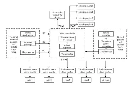
Figure 12:The system structure of rotated fixed-wing unmanned aerial vehicle (uav)The flight experiment is as shown in Fig.13.The entire model is made of EPS,which can reduce weight,energy consumption and cost.We use MPU6050 to measure the euler angle and acceleration.
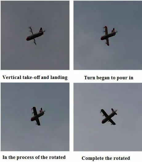
Figure 13:Tilt wing prototype flight test
And master computers collect flight curve of vertical take-off and landing mode,transition mode and airplane mode,as shown in Fig.14.The result confirms that the fluctuation of the curve of three airplane attitude angles is smaller.And it shows the flight process of QTW-UAV is stable.
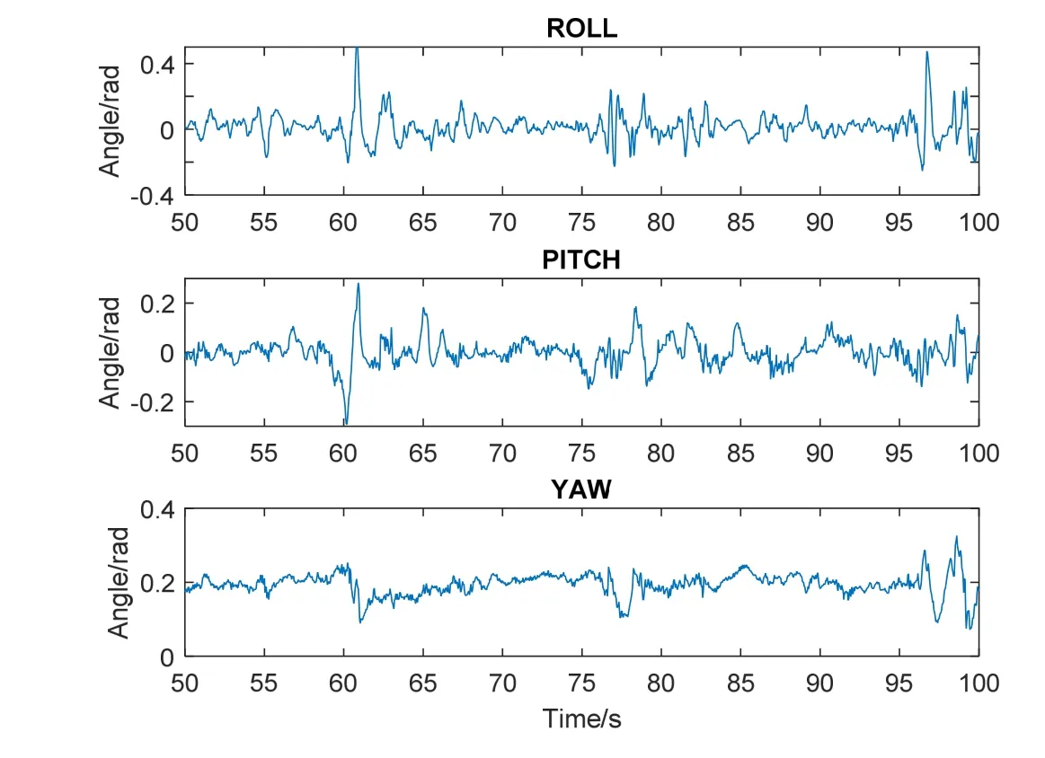
Figure 14:Roll,pitch and yaw attitude Angle curve
After we change the size of the wing and analyze the curve of pitch angle of three modes,we find it takes about 4 seconds to tilt wing- time of transition mode.While we enlarge the curve of pitch angle of three modes,the amplitude of jitter of drift angle is within the range of 0.28 rad~0.3 rad,as shown in Fig.15.If we increase the size of the wind to 1.05 times,the amplitude of jitter of drift angle is within the range of -0.25~0.18.It turns out that the flight is more stable than before because the amplitude of jitter of vertical take-off and landing mode,transition mode and airplane mode is smaller,as shown in Fig.16.The result shows optimizing the size of the wing can improve the flight stability within limits.

Figure 15:Pitch angle flight curve under normal area
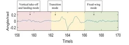
Figure 16:pitch angle flight curve at 1.05 times the area
6 Conclusion
In view of the kinetic stability problem of QTW-UAV in transition mode,this paper improves the stability by changing the mechanical structure parameters.The Lyapunov exponent method is used to construct the quantitative relationship between QTW-UAV and system kinetic stability,laying a solid theoretical basis for improving the system mechanical structure and kinetic stability.In this paper,the kinetic model of QTW-UAV is established,and the quantitative relation model between system structural parameters and kinetic stability is established according to the kinetic model.Finally,the software simulation results show that QTW-UAV can improve the stability by increasing the wing area within a certain range,and the validity and constructability of the theory is proved.For the kinetic stability problem existing in the QTW-UAV’s transition mode stage,the paper divides the transition mode into multiple parts from the tilt angle.The analysis shows that QTW-UAV has little effect on improving the stability of the system stability when QTW-UAV wing area is increased at the tilting start stage;when wing tilt angle is greater than 30°,and the wing area increase has a significant effect.Meanwhile,it is proved that Lyapunov exponent method has the advantages of feasibility and simple operation compared with Lyapunov direct method.At last,the experiment shows that increasing the wing area can improve the stability within limits.
Acknowledgments:This research is supported financially by Natural Science Foundation of China (Grant No.51575283,No.51405243).
 Computers Materials&Continua2019年6期
- Computers Materials&Continua的其它文章
- Development of Cloud Based Air Pollution Information System Using Visualization
- A Learning Based Brain Tumor Detection System
- Shape,Color and Texture Based CBIR System Using Fuzzy Logic Classifier
- LRV:A Tool for Academic Text Visualization to Support the Literature Review Process
- Application of Image Compression to Multiple-Shot Pictures Using Similarity Norms With Three Level Blurring
- On Harmonic and Ev-Degree Molecular Topological Properties of DOX,RTOX and DSL Networks