
Research on robust control strategy of single DOF supporting systemof MLDSB based on H∞ mixed-sensitivity Method①
2020-10-09 07:38ZhaoJianhua赵建华ChenTaoHanFangGaoDianrongDuGuojun
High Technology Letters 2020年3期
Zhao Jianhua (赵建华)②, Chen Tao, Han Fang, Gao Dianrong, Du Guojun
(*College of Civil Engineering and Mechanics, Yanshan University, Qinhuangdao 066004, P.R.China) (* *Fluid Power Transmission and Control Laboratory, Yanshan University, Qinhuangdao 066004, P.R.China) (* * *Jiangsu Provincial Key Laboratory of Advanced Manufacture and Process for Marine Mechanical Equipment, Zhenjiang 212003, P.R.China)
Abstract
Key words: magnetic-liquid double suspension bearing (MLDSB), single degree of freedom (DOF) supporting system, H∞ mixed-sensitivity method, state feedback controller, robust stability
0 Introduction
The hydrostatic bearing is introduced into the magnetic levitation to form magnetic-liquid double suspension bearing (MLDSB). And MLDSB is mainly supported by electromagnetic levitation and assisted by hydrostatic, and then its bearing capacity and rigidity can be greatly improved. It’s suitable for medium speed, heavy load and the occasions where it is frequently started and the dynamic pressure support is difficult to achieve actual performance[1]. Due to the coupling between electromagnetic system and hydrostatic system and inertia-gyroscopic effect caused by high-speed rotating of the rotor, the model parameter uncertainty and unmodeled dynamic characteristics of MLDSB can be aggravated and the deviations between the real model and the theoretical model are produced, and then the control accuracy and robust control stability can be improved.
Recently, lots of scholars had deeply studied the robust control and suppressing the unbalanced vibration of electromagnetic bearing system and achieved fruitful achievements.
Long et al.[2]established kinetic models of rotor system of 5-freedom electromagnetic bearing and analyzed unbalanced vibration caused by the deviation of the rotor center of mass. The study showed that the robust stability of the rotor system was great and the vibration of rotor could be restrained effectively. Xu et al.[3]established mathematical model of 5-freedom electromagnetic bearing and analyzed the influence of gyroscopic coupling and inertia coupling on the model of the system. Based on sensitivity weighting factor and supplementary sensitivity weighting factor, single degree of freedom (DOF)H∞controller and 2-DOF centralized controller with inertial coupling were presented. The results showed that the dynamic and static characteristics of the system were great and the robustness and the ability of restraining disturbance were strong. Gu et al.[4]optimized the design of axial magnetic bearing controller based on mixed sensitivity methodH∞control. The research shows that single DOF support system of MLDSB withH∞controller has a good robust stability, comparatively strong robust and the ability to suppress unbalanced external disturbances compared with traditional PID control. Zhang et al.[5]experimentally researched on the influence of temperature, rotating speed, leakage flux and eddy current on electromagnetic force and solved the contradiction between high rotating speed and high stiffness caused by the complex nonlinearity of the electromagnetic bearing of the electromagnetic bearing grinding machine system. The result showed that high rotating speed and high stiffness can be achieved and the effect of electromagnetic perturbation on the system can be overcome whenH∞controller is used to control the electromagnetic coil current. Li et al.[6]experimentally studied the electromagnetic bearings-flexible rotor, and the results showed that the rotating speed of the rotor successfully exceeded the second flexible critical speed under robustH∞controller, and then the operation accuracy and safety can be improved sharply. Aiming at the interference caused by the mass imbalance of the rotor of electromagnetic bearing, Shang et al.[7]presented a gain-scheduling electromagnetic controller of multi-objective performance requirement. The results showed that electromagnetic bearing system had good robust stability and the ability to restrain unbalanced external disturbance under the action of the controller.
In conclusion, many scholars devoted to unbalanced vibration of flexible rotor and parameter uncertainty of electromagnetic bearing system. However, there are no relevant researches about robustH∞control of MLDSB.
When the rotor rotates at high speed, the unbalanced vibration caused by the deviation of mass center can result in the inertia coupling and gyroscopic coupling, and then the robust stability can be reduced sharply. However, robust stability is the basis of the design and operation of MLDSB. Therefore, the dynamic equation of the radial 4-DOF MLDSB system is established, and the uncertainties and its influencing factors caused by the unbalanced vibration are revealed.H∞controller is designed withH∞hybrid sensitivity method and the control performances of state feedback andH∞controller are compared.
1 Mathematical model of MLDSB
1.1 Working principle of bearing system
Eight poles are circumferentially distributed in form of NSSNNSSN in MLDSB. The number of turns of each coil is the same, and 2 adjacent opposite poles are a pair of poles, and the magnetic loop and magnetic force are generated between the magnetic poles and flux sleeve. Inlet hole is processed in each magnetic. As fluid flows through the gaps between the poles and the flux sleeve, large liquid resistance are formed and then the hydrostatic pressure is established on the magnetic pole. After that, static bearing force is generated. Initially, the electromagnetic force and hydrostatic force of each magnetic poles are equal, and two adjacent opposite magnetic pole pairs can be called as supporting unit.
A single DOF supporting system in the vertical direction is taken as an example. Its regulating principle and force diagram are shown as Fig.1 and Fig.2. In the initial state, the bias currents of the upper and lower electromagnetic coils arei0and the thickness of upper and lower oil film are 30 μm. When the external loadfacts on the rotor, the displacement of the rotor isxand the thicknesses of the oil films of the upper and lower supporting cavity change, and then the hydrostatic supporting force is generated. The controlling currenticgenerated by the electromagnetic system are transferred to the upper and lower coils and then the electromagnetic supporting force is generated. The rotor is adjusted by electromagnetic force and hydrostatic force together so that it can return to the balance position again[8].

Fig.1 Single DOF support regulation principle of MLDSB

Fig.2 Force diagram of single DOF MLDSB
1.2 Mathematical model of radial MLDSB
The force diagram of the rotor is shown as Fig.3, and the meanings of parameters are shown as Table 1.

Fig.3 Rotor of MLDSB
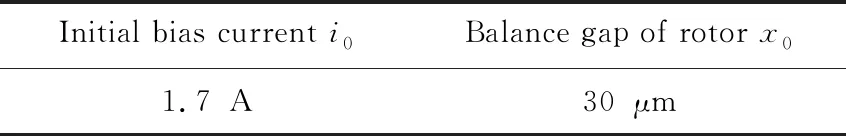
Initial bias current i0Balance gap of rotor x01.7A30μm
According to Fig.3, the radial motion equation of the rotor of MLDSB are shown as follows.
(1)
where,m—— Mass of rotor, kg;m=10;
xc——X-displacement of mass center, m;
xc=(bxa+axb)/l;
yc——Y-displacement of mass center, m;
yc=(bya+ayb)/l;
xa——X-displacement ofA-end of rotor, m;
ya——Y-displacement ofA-end of rotor, m;
xb——X-displacement ofB-end of rotor, m;
yb——Y-displacement ofB-end of rotor, m;
θx——X-angle of rotor, rad;θx=(yb-ya)/l;
θy——Y-angle of rotor, rad;θy=(xb-xa)/l;
l——Distance betweenAandB, m;l=0.532 m;
a——Distance betweenAand mass center, m;
a=0.3105 m;
b——Distance betweenBand mass center, m;
b=0.2215 m;
ω——Z-rotational speed of rotor, rad/s;
Ir——X-rotational inertia andY-rotational inertia of rotor, kg·m2;
Ir=0.0225 kg·m2;
Ia——Z-rotational inertia of rotor,kg·m2;
Ia=8.85×10⁻⁴kg·m2;
Mx——X-torque of rotor, N·m;
My——Y-torque of rotor, N·m;
fx——X-interference, N;
fx1=fh,d+fe,u;fx2=fh,u+fe,d;
fx3=fe,d,1+fe,u,1;fx4=fh,u,1+fe,d,1;
fy——Y-interference, N;
fy1=fh,b+fe,f;fy2=fh,f+fe,b;
fy3=fe,b,1+fh,f,1;fy4=fh,f,1+fe,b,1.
The resultant force of magnetic and hydrostatic system can be linearized in the equilibrium position as follows[8].
(2)
where,kr——Displacement stiffness coefficient,N/m;kr=1.64×107N/m;
kv——Velocity stiffness coefficient,N/(m/s);kv=1.8×105N/(m/s);
ki——Current stiffness coefficient,N/A;ki=5100 N/A;
ixa,ixb——Control current ofA-end andB-end alongX-axis,A;
iya,iyb——Control current ofA-end andB-end alongY-axis,A;


(3)
where,Ais state matrix,Bis control matrix,Cis output matrix andDis direct transfer matrix.
By substituting Eq.(2) into Eq.(1), the expressions of matricesA,B,CandDcan be obtained as follows.
(4)
It can be seen from matrixAthat the coupling characteristics of MLDSB system are mainly related to the rotational speed and the inertia of the rotor. When the rotational speed is low, the inertial coupling and gyro coupling can be ignored, and then the radial transfer function can be obtained as follows.
(5)
2 Controller design of MLDSB
2.1 H∞ mixed sensitivity control
Taking single DOF supporting system as an example, the principle block diagram of the control system is shown as Fig.4.

Fig.4 Principle block diagram of control system
In Fig.4,r,e,u,d,y,K,Pare respectively reference input, tracking error, control quantity, external interference, system output, controller and controlled object. Then the sensitivity functionS(s), supplementary sensitivity functionT(s) and functionR(s) can be obtained respectively as follows.
(6)
where, ‖S‖∞is a measure of the suppression capability to low-frequency interference, ‖T‖∞is a measure of the suppression capability to high frequency unmodeled dynamic and reappearance capability to reference input, and also the measure of the allowable amplitude Δ of multiplicative perturbation (I+Δ)P. While ‖R‖∞is the measure of the allowable amplitude ΔGof the additive perturbationG+ΔGand the suppression capability of the control output[9].
The nominal modelG0(s) is difficult to reflect the actual controlled system. The relationship between actual model and nominal model isG(s)=G0(s)+ΔG(s),ΔG(s) is a bounded perturbation.
According to the robust stability theory, if controllerK(s) which can makeG0(s) closed-loop stably exist, for any bounded perturbation ΔG(s) which can meet ΔG(s)≤W3(s), the sufficient condition of the closed-loop stability of the system is shown as follows.
|T(s)W3(s)|≤1
(7)
where,W3(s) is a supplementary sensitivity weighting function.
For external interferenced, |S(s)W1(s)|≤1 is true by selecting reasonably the sensitivity weight function, and then the closed-loop transfer function can be reshaped in the frequency domain in order to suppress the influence of external interference on system output.
2.2 Controller design and simulation
It can be seen from the state equation of radial MLDSB that the uncertainty includes the parameter uncertainty caused by the linearization of the supporting force and the dynamic uncertainty caused by the inertial coupling and gyroscopic coupling. The uncertainty of parameters is generally caused by the large floating of the rotor, and it includes uncertainty of displacement stiffness coefficientkx, uncertainty of velocity stiffness coefficientkvand uncertainty of current stiffness coefficientki.

(8)
Due to the small pole moment of inertia and rotational speed, the multiplicative uncertainty Δ2(s) caused by the inertial coupling can be shown as follows.
(9)
The expression of same frequency centrifugal interference caused by the eccentricity of the rotor isFd=mεω2cosωt, eccentric distance isε=5 μm[10]. So displacement amplitude of the rotor caused by disturbance can be obtained as follows.
(10)
Due to the highest rotational speed (6 000 r/min) of MLDSB, the corresponding interference amplitude can be obtained as follows.
|d|=9.4×10⁻⁶cos(618t)
(11)
In order to ensure that the radial amplitudexmof the rotor does not exceed one tenth of the radial gap of the bearing (30 μm), so the maximum amplitude of expected sensitivity functionS(s) can be obtained whenω1=618 rad/s as follows.
(12)
So radial transfer function of MLDSB can be obtained as follows.
(13)
It can be seen from Eq.(13) thatP0(s) contains an unstable pole. In order to suppress the low frequency noise, the inverse of the sensitivity weighting functionW1(s) should be greater thanS(jω1) nearω1position, SoW1(s) can be expressed as follows.
(14)
To eliminate greater saturation in order to prevent damaging the equipment and increasing the order of the controller,W2(s) is usually assumed as a scalar quantity.
W2(s)=0.0002
(15)
Since the supplementary sensitivity weighting functionW3is related to the bandwidth of the system, the dominant pole of MLDSB is 90.65/s and the bandwidth can be identified as 80 rad/s, and thenW3and its singular value can be shown as follows.
(16)
It can be seen from Fig.5 that the singular valueW3is above Δ1(s) and Δ2(s), so the overflow phenomenon of the controller can be avoided to obtain good control effect.
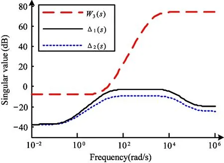
Fig.5 Curves between W3 and singular value
By using Matlab software, transfer functionK(s) ofH∞controller can be obtained as follows.
(17)
where,T4=60.6,T3=5.472×10⁵,T2=4.813×10⁸,T1=9.612×10¹⁰,T0=2.751×10¹², Г3=3.831×10⁴, Г2=2.681×10⁷, Г1=-3.911×10⁹, Г0=1.479×10¹⁰.
The singular value characteristics of the weighting function of complementary sensitivity functionT(s), sensitivity functionS(s) are shown as Fig.6 and Fig.7.
It can be seen from Fig.6 and Fig.7 that reciprocal of supplementary sensitivity weighting function 1/W3(s), reciprocal of sensitivity weighting function 1/W1(s) are respectively above complementary sensitivity functionT(s) and sensitivity functionS(s). Meanwhile,W1(s) has low connectivity and its cut-off frequency is less than that ofW3(s), soW1(s) can satisfy the requirement of weighting function[11,12].

Fig.7 Sensitivity function and singular value characteristics
By using Matlab Simulink simulation tool, the floating characteristic curve (step signal, amplitude is 1 μm) of single DOF support system can be presented as Fig.8.

Fig.8 Floating characteristic curve of suspension clearance
It can be seen from Fig.8 that adjustment time and overshoot of single DOF supporting system withH∞mixed sensitivity controller are both smaller than that with the state feedback controller[12,13].
When the rotor is supported stably at the rotating center, its floating characteristic curve under the situation that 500 N pulse interference is suddenly added att=3 s can be shown as Fig.9.

Fig.9 Floating characteristic curve of pulse external excitation
It can be seen from Fig.9 that the offset distances underH∞mixed sensitivity control[14,15]and under the state feedback control are 2 μm and 5 μm respectively.
The floating characteristic curve of suspension clearance is shown as Fig.10 when amplitude is 500 N and frequency is 100 Hz.

Fig.10 Floating characteristic curve of sine external interference
It can be seen from Fig.10 that the amplitude of the rotor underH∞hybrid sensitivity control is 1.5 μm (a tenth of the radial gap length) while 7 μm under state feedback control. To sum up, single DOF support system of MLDSB withH∞controller has good dynamic[16], robust stability and the ability to suppress unbalanced external disturbances.
3 Conclusion
The mathematical model of radial MLDSB system is established, the uncertainty of controlled object is evaluated based onH∞hybrid sensitivity optimal control theory, and the weighted function is obtained.
MLDSB withH∞hybrid sensitivity control has good dynamic characteristics, stiffness, robust stability and vibration suppression ability.
 High Technology Letters2020年3期
- High Technology Letters的其它文章
- A novel flow control scheme for reciprocating compressorbased on adaptive predictive PID control①
- Fraud detection on payment transaction networks via graph computing and visualization①
- MSONoC: a non-blocking optical interconnection network for inter cluster communication①
- Research on full-period acquisition method for diesel enginebased on self-adaptive correlation analysis①
- PRF: a process-RAM-feedback performance model to revealbottlenecks and propose optimizations①
- Research on oil film characteristics of piston pairin swash plate axial piston pump①