
Spatio-temporal evaluation of Zr plasma parameters in a single-beam-splitting double-pulse laser-induced plasma
2021-02-27 09:17ArnabSARKARandManjeetSINGH
Plasma Science and Technology 2021年2期
Arnab SARKAR and Manjeet SINGH
1 Fuel Chemistry Division, Bhabha Atomic Research Centre, Mumbai 400 085, India
2 Homi Bhabha National Institute, Anushaktinagar, Mumbai 400 094, India
Abstract
Keywords: LIBS, single-beam-splitting, double pulse, spatial-temporal evolution, plasma temperature, electron density
1.Introduction
The increasing popularity of laser-induced breakdown spectroscopy(LIBS)in different fields of modern science and technology is credited to the simplicity of the analysis method and its capability to analyze a wide range of samples, covering the entire periodic table.Details of the methodologies in different fields, such as the environment [1–5], nuclear[6–11], industry [12, 13], homeland security [14, 15], are widely available in the literature.In spite of its increasing popularity, a significant disadvantage of the LIBS technique is the lack of sensitivity and reproducibility of the processes which lead to the formation of laser-induced plasma, i.e.ablation,atomization and excitation.These restrictions lead to a poor limit of detection (LOD) compared to other spectrometric methods, such as inductively coupled plasma atomic emission spectroscopy or flame atomic emission spectroscopy[16–18].
Several approaches have been suggested to improve LIBS sensitivity by different research groups.These approaches can be classified mainly into two primary classes: (a)laser ablation coupled with additional excitation sources, viz.laser (double-pulse LIBS) [16, 19, 20], magnetic (magneticfield-assisted LIBS)[21,22],microwave(microwave-assisted LIBS) [23, 24], hollow cathode lamp (spark-discharged LIBS) [25], etc, and (b) plasma confinement [26, 27].The first class of approach implies an increase in the cost of the set-up, whereas the second class increases the complexity of the analysis, although both succeeded in achieving high sensitivity.Among all these possible approaches, the doublepulse configuration (DP-LIBS) has significantly gained importance among researchers.The DP-LIBS approach, first suggested by Piepmeieret al[28]based on their observations,showed that a significant fraction of the laser energy is reabsorbed by the plume instead of ablating the sample.Hence,if a second laser is focused on this plume, there will be enhancement in the excitation of species in the plume,thereby increasing emission intensity.
A detailed literature survey of DP-LIBS reveals that the key condition for signal enhancement in DP-LIBS is a delay of 1–5 μs between the two pulses’ [19, 29–40] separately generated laser pulses.Guanget alused a relatively simpler DP-LIBS signal enhancement method by splitting the single laser beam and using them as two laser pulses which simultaneously ablate the sample from different angles, known as single-beam-splitting double-pulse LIBS (SBS-DP-LIBS)[41].The only requirement of the technique is that it has a proper optical geometric configuration.The method provides a financial advantage over the traditional DP-LIBS (orthogonal or collinear geometry) by using only a single laser source.In an SBS-DP-LIBS method, the inter-pulse delay depends on the optical path length difference (OPLD)between the two split laser paths.In laboratory conditions,the normally achievable OPLD would be in the range of 1–5 m,which translates to an inter-pulse delay of 3–16 ns.Generation of a 1–5 μs delay will require an OPLD of >300 m,which is not practically feasible under laboratory conditions.
DP-LIBS studies with ns range inter-pulse delays have been reported with marked differences in several plasma parameters compared to single pulse (SP)-LIBS experiments.Forsmanet aldemonstrated improvement in the material removal rate by employing an inter-pulse delay in tens of nanoseconds, with a zero inter-laser angle, i.e.collinear geometry [42].Maoet alshowed a significant increase in emission intensity, plasma temperature (Te) and crater depth volume by employing the 100–200 ns inter-pulse delay,again with collinear geometry [20].To the best of our knowledge,there are no published studies available in the ns inter-pulse delay configuration, except the study by Guanget al[41].This study reveals that the signal enhancement can also be achieved in the ns inter-pulse delay (SBS-DP-LIBS method)using a 50°–70° inter-laser angle and high laser-pulse energy(EL).The study compared signal enhancement by changing the inter-laser angle from 0° to 90° and, for both, the Al and Cu signal intensity increases many fold at the 50°–70° interlaser angle.The study proposed that the absorption zone formed in the leading edge of the plasma absorbs the major segment of the trailing edge of the first laser pulse.This results in the reduced coupling between the laser ablation pulse and the sample, and is one of the reasons behind the poor sensitivity in LIBS.Since this absorption zone forms and propagates along the direction of the incident laser, a second laser fired at a 50°–70° angle to the first laser avoids the already existing absorption zone and this results in strong coupling between the laser and the sample [41].The aim of the present work is to systematically examine different plasma parameters in the plasma formed in SBS-DP-LIBS and SPLIBS.The two important plasma parameters, plasma temperature (Te) and electron number density (Ne), have a significant influence on the emission line intensity.Zr-2.5% Nb alloy is used as the sample, and the observed Zr emission lines are measured to determine theTeandNe.The comparison of SBS-DP- and SP-laser excitation for LIBS is carried out at a constant total excitation energy.Spectroscopic diagnosis of the plasma was accomplished using Boltzmann plots and the Saha–Boltzmann equation.The influence of theELon the plasma parameters was also investigated.Spatial images of plasma emission intensity were also recorded to understand the dynamics of plasma expansion.
2.Experimental
2.1.Instrumentation
A laboratory assembled system has been used in the present LIBS study (figure 1).A 532 nm, 6 ns pulse, Nd:YAG laser(Brilliant B, Quantel, France) was focused using a planoconvex lens to produce a laser-induced plasma.At the maximum energy of 440 mJ, with a repetition rate of 10 Hz, the laser spot size was ∼150 μm.TheELwas measured with an energy meter (Ophire Photonics, Israel).In the SP-LIBS analysis, the laser is focused onto the sample through a periscope-like mirror design (M1, M2 and M3) and a planoconvex lens (L1, focal length 10 cm).For SBS-DP-LIBS, a beam-splitter (BS) (50:50, Thorlabs, BSW26) is placed between the M3 and L1 at a 45° angle to the direction of the laser.The BS is mounted on a 90°flip mount,so that both SPLIBS and SBS-DP-LIBS modes can be used by simply flipping the mount of the BS,without changing any other part of the set-up.The BS causes less than 1 mJ loss in total energy with respect to the single-beam energy.Since the loss of laser energy due to the BS is very small compared to the specified laser energy fluctuation of 3%, this loss was neglected.The initial pulse is divided into two equal energy laser pulses by the BS:one in reflection,and the other in transmission mode.The transmitted mode gets focused on the sample through the L1 lens, similar to SP-LIBS.The reflected mode laser beam,which is aligned horizontally to the sample surface,entered a set of optical systems consisting of three mirrors(M4,M5 and M6)and a 10 cm focal length plano-convex lens(L2)to reach the sample surface at an angle of 60° with respect to the transmitted mode laser.The difference between(BS-M4-M5-M6-L2) and (BS-L1) is the OPLD and is found to be 1.1 m,which corresponds to an inter-pulse delay of ∼4 ns.In the present lab set-up, using a three mirror geometry, the maximum OPLD one can obtain is ∼2 m,which is ∼6.5 ns.Due to this very limited difference in delay time between the two pulses, optimization of the delay time was not carried out in the present study.
A collimator was used to collect the plasma emission light at a 45° angle with respect to the initial laser beam direction.The collimator is a light collection system consisting of an off-axis UV-grade quartz lenses and mirrors(CC52, Andor, UK).The collected laser-induced plasma(LIP)emission is focused onto the entrance of an optical fiber bundle(200 μm core diameter)and imaged onto the entrance slit (10 μm width) of a 750 cm focal length Czerny–Turner spectrometer(Shamrock SR750,Andor,UK)equipped with a 2400 lines/mm grating via two bi-convex lenses(L3 and L4).The observed resolution was 25 pm full width at half-maximum, which could be achieved simultaneously over a spectral window of 6 nm.

Figure 1.A schematic of the SBS-DP-LIBS system used in the present study.M, L and OF represent the mirror, lens and optical fiber,respectively.The line array fiber bundle design for imaging the plasma is shown in the inset.
For plasma spatial imaging and study, instead of the collimator, an optical set consisting of two bi-convex quartz lenses and a line array fiber bundle(4.9 mm high×0.245 mm wide)was used,as shown in the inset in figure 1.The line array fiber bundle set was used after removing the collimator set.A total of 19 fibers,each with 200 μm core diameter,formed the line array fiber bundle.The two bi-convex lenses magnify the plasma 1.5× on the fiber bundle.The line array fiber bundle similar to the above is also coupled to the Czerny–Turner spectrometer.By imaging multiple plasmas above the sample surface positioned at different heights,the relationship between an individual fiber and its height is calculated,which comes to 0.37 mm per fiber.For spatial analysis, the area under the individual fiber image was analyzed.This signal collection efficiency heavily depends on the collimator and fiber configurations.
2.2.LIBS analysis
A certified Zr standard sample (Zr-2.5% Nb) received from the Nuclear Fuel Center,Department of Atomic Energy,India is used for the present study.The material is 97.4% pure Zr with trace impurities of C (∼80 ppm), Cr (∼0.13%) and Fe(∼0.53%).To understand the effect of theELon the plasma intensity and other parameters,theELis varied and spectra are recorded.TheELused in this study are 30, 50, 70, 90, 110,130, 150, 170, 200, 210 and 240 mJ.These energies were used in both SP-LIBS and in SBS-DP-LIBS,where the beam gets split into two equal parts with pulse energy ofEL/2.The temporal profiles of the Zr emission lines were calculated by changing thetdand thetw.Twotwconditions are used for this study.Initially,thetwwas set at 50%oftdto obtain good time resolution for the plasma evaluation study, particularly in the early lifetime,and the other setting was a constanttwof 25 μs to allow acquisition of plasma emission of nearly the full plasma lifetime.Thetdused in this study are 0.05, 0.075,0.115, 0.175, 0.265, 0.395, 0.595, 0.895, 1.345, 2, 3, 4.5, 7,11, 17 and 26 μs.Fifty laser shot accumulations per spectra were used for LIBS spectra recording.All experiments were carried out at atmospheric conditions.
3.Results and discussion
3.1.Selection of emission lines
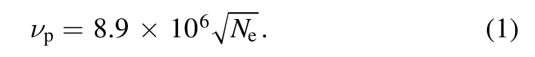
Zr as an element of the 5th row in the periodic table is expected to have a relatively complex spectrum,and this was the reason for choosing a high resolution spectrograph for this study.As stated previously,the use of 2400 lines/mm grating limits the simultaneous acquisition to only a 6 nm spectral window.Since the goal of the study is to understand the plasma properties in the two modes of excitation (SP- and SBS-DP-LIBS), study of the spectrum recorded in a single spectral window is required, to eliminate the fluctuation prevailing in theEL, detector noise, laser–matter interaction,etc.The selection of the 6 nm spectrum segment is carried out based on the following criteria: (i) sufficient Zr and Nb emission intensity for spectral fitting, (ii) the availability of spectrally pure emission lines,(iii)the availability of multiple Zr(I)emission lines with a wide range of upper transition state energy forTecalculation, and (iv) availability of at least one spectrally pure Zr(II) emission line forNedetermination.Based on these criteria a 404.3–410.2 nm emission spectrum segment was selected in the present study.The selected spectral region and the assigned emission lines (table 1) are shown in figure 2 [43].
3.2.Zr emission intensity and background
Under identical acquisition conditions of 2 μstdand 25 μstw,LIBS spectra were recorded at differentELin the range of 30–240 mJ using both types of excitation modes.The trends of Zr(II)407.108 nm and Zr(I)407.27 nm spectral intensities as a function of theELare presented in figure 3.In the SP mode (circular point), both the atomic and ionic emission lines of Zr show an increasing intensity trend with increasingEL.However, both the emission lines start to show non-linearity atEL> 90 mJ, and atEL> 120 mJ the intensities get saturated.This is a typical LIBS intensity pattern withEL,exhibiting the occurrence of plasma shielding and selfabsorption atEL> 90 mJ.Plasma critical density is defined as the plasma density, where plasma frequency is equal to laser frequency.At a lowerELthe electron density in the plasma remains below the critical density, which allows the laser to reach the target causing ablation.With increasing ablation the plasma electron density increases near to critical density,and the plasma becomes opaque to the incident laser,which shields the target.This phenomenon,known as plasma shielding, leads to saturation of plasma emission when the plasma becomes highly dense.This phenomenon reduces the transmission of the tailing edge of laser-pulse energy along the beam path by forming an absorption zone and thereby nullifying the effect of higher energy deposition.Again, in dense plasma, the self-absorption process occurs due to the absorption of emission lines emitted from the hot internal coreof the plasma, by the unexcited species present in the cold outer-core of the plasma,making it difficult for the detector to detect the increasing intensity and which is reflected by the self reversal in emission lines [44].Both these processes are responsible for intensity saturation with increasingEL, as shown in figure 3.The error bar on the intensity values is the standard deviation of three replicate analyses.These variations are primarily due to the sample surface design,which is not completely flat as it contains lots of voids, causing fluctuations in the surface of the lens distance,hence fluctuations in emitted intensity.

Table 1.Zr and Nb emission lines identified in the selected 404.3–410.2 nm region along with their spectroscopic parameters [43].
Under the SBS-DP-excitation mode, the intensity versusELexhibits a different trend.The square point in figure 3 shows the trend of Zr(II) 407.108 nm and Zr(I) 407.27 nm emission intensity against the varyingEL.The signal enhancement factor (SEF) of an emission intensity is defined as the ratio of the signal intensity in the SBS-DP mode to the SP mode.The higher SEF in the SBS-DP mode is clearly observed in figure 3.The Zr(I) emission line though shows the presence of plasma shielding and self-absorption, but contrary to the SP mode, these two phenomena are less effective,causing higher signal strength and also non-linearity in the intensity trend to start at ∼120 mJEL.

Figure 2.The LIBS emission spectrum in the 404.3–410.2 nm region obtained for the Zr-Nb2.5%LIP study at a td of 2 μs and tw of 25 μs using SP-LIBS.

Figure 3.Intensity profiles of (a) Zr(I) 407.27 nm and (b) Zr(II) 407.108 nm against EL, using SP-LIBS (circles) and SBS-DP-LIBS(squares).The SEF in the signal intensity is shown using the dotted line with the right-hand axis.
The formation of a diffused absorption zone along the direction of the incident laser is well documented [44].This absorption zone is responsible for the plasma shielding effect.The plasma shielding happens due to the combination of both absorption (due to photo-ionization and inverse bremsstrahlung(IB))and reflection of incident laser photons by the plasma.The reflection of laser photons depends on the plasma frequency (νp).If the laser frequency (νL) is smaller than the νp, laser photons will be reflected [45].The second harmonic of the Nd:YAG laser corresponds to a νLof 5.64×10¹⁴Hz.The νpis calculated using equation (1),
The νpwas found to vary from 1012to 1.5×10¹³in all the experiments in the study, which is smaller than the νL, and hence the energy loss due to reflections of laser photons can be assumed to be insignificant in the present case.The rate of photon absorption by photo-ionization (especially by multiphoton and impact ionization) and photon-free electron-IB absorption increases with increasingEL[46].In SP-excitation mode, the plasma enters into a self-governing regime atEL> 100 mJ.With increasing ablation of the sample due to increasingEL, the plasma density increases, resulting in an increase in laser photon absorption by IB: multi-photon absorption.As the absorption of the photons by the plasma increases, the sample ablation from the target sample decreases, which in turn decreases the density of the plasma.This consequently increases the laser photon absorption by the target and enhances the laser ablation, which, in order,again increases the plasma density.Caruso and Gratton showed that the density and temperature of the plasma adjust in such a method that the plasma absorbs the same number of photons to maintain this self-governing regime [47].In SBSDP mode the totalELis divided into two equal parts,and one half gets focused on the sample surface from a direction perpendicular to the sample surface.Since the energy is lower, the absorption zone thickness is small and less diffused.The second half of theELgets focused on the sample surface at an angle 60°to the initial laser-pulse direction after∼4 ns time.This angle causes less interaction of the second laser with the initial absorption zone, and hence results in better laser–sample coupling leading to higher emission intensity, as seen in the study.Similar signal enhancement results were also observed by Guanget alat the 60° interpulse angle[41].The reductions of laser photon reflection by the plasma also improve the laser–plasma coupling.Again,in SBS-DP-LIBS, the second pulse is interacting with a preformed plasma (lesser density plume), where one can expect increased laser-heating of the plasma [48].The increase in emission intensity is a combined effect of all these processes.
Interestingly, the Zr(II) 407.108 nm line intensity shows a linear increasing trend against theELin SBS-DP-LIBS.The absence of self-absorption for ionic lines may also be due to the selection of a weaker line in the present study.Also, the absence of self-absorption may be attributed to the fact that a ns-laser-induced plasma usually consists of ∼10%–20%ionic abundances, which leads to a reduced probability of selfabsorption.Further investigations are required for complete understanding.The Nb(I) 410.092 nm emission pattern also shows a similar intensity pattern to the Zr emission lines.
3.3.Plasma temperature (Te)
Aragonet aldiscussed in detail the application of optical spectroscopy for laser-induced plasma characterizations which include both measurements of theTeandNe[49].Among the described methods the Boltzmann plot technique was used in the present study for theTecalculation in view of its accuracy.All the Zr(I) emission lines shown in table 1 were used in the Boltzmann equation technique, except for a few emission lines.Zr(I)407.653 nm,Zr(I)408.229 nm,Zr(I)408.770 nm, Zr(I) 409.080 nm were not used in the Boltzmann plot due to high spectral interference.Zr(I)409.930 nm and Zr(I) 405.445 nm were not used as they were resonant and near resonant emission lines, which are more susceptible to showing the self-absorption effect.The recorded spectra at 2 μstdand 25 μstwwere used for theTecalculation.TheTeis estimated within 10%uncertainty,which arises mainly due to uncertainties in theAijvalues and in the measurement of the integrated line intensities used.Figure 4(a) shows the obtainedTeusing the Boltzmann plot against the depositedEL.
3)微机继电保护装置中接线错误也是其常见故障之一。在电力运行期间出现接线错误,往往要在对新装电路进行全面的检验和调试后才能发现,由于线路本身的复杂性,处理起来难度较大,因此,接线错误在微机继电保护装置故障中,解决起来相对较为麻烦。
The temperature pattern as a function of theELcan be divided into two segments,EL< 100 mJ andEL> 100 mJ.In the first segment (EL< 100 mJ), theTeincreases from 6000 K to 10 000 K with increasing theELfrom 30 mJ to 100 mJ, irrespective of the mode of excitation.With the increase in the depositedEL, both the laser–matter and laser–plasma interactions change.Improvement of laser–plasma coupling leads to an increase in the mass ablation from the sample surface.Also,the increase in photon absorption by the plasma leads to an increase in theTe.With a further increase in theELabove 100 mJ, plasma shielding starts to interfere with the process of mass ablation,as discussed in the previous section.Increasing plasma shielding means a reduction in the amount ofELreaching the sample surface, thereby less ablation, and lessTe.Figure 4(a) clearly shows the saturatedTetrend(10 000 K) with increasingELin the SP-LIBS spectra.But,for the SBS-DP-LIBS data, theTeincreases with increasingEL,even after 100 mJ.The enhancement of theTein SBS-DP mode can be attributed to the reduction in the plasma shielding effect, as discussed in the previous section.Again,the second pulse, which is interacting with the preformed plasma, causes improved laser-heating [48].The trend of theTein the present study for SP-LIBS is comparable with the results shown by Harilalet al[46].The reduced hindrance thus increases the laser–sample coupling, resulting in more sample ablation and hence a higherTe.The enhancement of theTeincreases with an increase in theEL.At 240 mJ,theTein SBS-DP-LIBS is 17 000 K,which is almost twice theTein SP-LIBS of 8500 K.Since the second laser pulse interacts with a less diffused absorption zone, the shielding effect is less pronounced in SBS-DP-LIBS than the SP-LIBS spectra,but the shielding effect is not completely absent.The presence of this less effective but existing shielding effect is reflected by the change in slope in theTeversusELplot after 100 mJELup to 240 mJEL,the highest used in the study.TheTeandNepatterns in 4 μstdand 25 μstwwere found to be similar to that observed in figure 4.

Figure 4.(a) Te and (b) Ne as a function of EL for both excitation modes (SP and SBS-DP) of LIBS.
3.4.Plasma electron density (Ne)
For measurement ofNe, two methods are reported in the literature: the Stark broadening method [50–53] and the Saha–Boltzmann equation[27,53–56].The first method is based on the broadening of emission lines due to the collisions of the emitting species with electrons and ions.But the method requires the knowledge of the electron impact parameter (W)of the emissing species,which is often not available,as in the present case.Hence,the alternative Saha–Boltzmann equation method, using the emission line intensities of an element in two consecutive charge states was used for theNecalculations[49].Zr(II) 407.108 nm and Zr(I) 407.270 nm emission lines were used for the calculation of theNeas a function of theELranging from 30 mJ to 240 mJ under both excitation mode conditions, as shown in figure 4(b).Our previous study [57]has shown that theNecalculated by the Saha–Boltzmann equation method deviates from theNemeasured by the Stark broadening method, but a strong linear co-relation of the twoNevalues measured by the two different methods exists.This indicates the applicability of the Saha–Boltzmann equation method to a temporal profiling study.
The uncertainty in theNein figure 4(b) is the one standard deviation of triplicate analysis.The profile of theNeas a function of theELwas found to increase with the increasingELlinearly,untilEL≤ 100 mJ.ForEL> 100 mJ a different trend under different excitation modes can be seen.TheNecalculated from SBS-DP-LIBS spectra is higher than that obtained for SP-LIBS.The higherNeis due to the higher sample ablation in the SBS-DP mode, as discussed previously.AtEL> 100 mJ the plasma shielding effect in SP-LIBS is clearly observed.TheNein SPLIBS gets saturated at 100 mJELand remains nearly unaffected with the increase in theEL,since plasma shielding is blocking the laser from reaching the sample surface.
The calculation ofNeandTewas carried out under the assumption of local thermodynamic equilibrium (LTE) in the transient plasma.When the electron–electron collision is the major route of de-excitation in the plasma, the plasma is said to be in LTE.A rule of thumb proposed by McWhirter for LTE to exist is based on a critical electron density,which requires the collision rate to be at least ten times of the radiative rate.For Zr species, the lowest limit forNeis 3×10²²m−3at 30 mJ and 6×10²²m−3at 240 mJ.The calculatedNevalues are significantly greater than the LTE approximation limit, implying the validity of the analysis.
3.5.Spatial-temporal evolution of plasma
TheTeandNepatterns in the plasmas generated through two different modes of excitation clearly show the existence of different types of laser-induced plasma, especially at highELirradiations.To understand the plasma evolution not only temporally but also spatially with respect to the 1st laser-pulse axis,temporal imaging of the plasma using line array fiber bundles was carried out.Figure 5 shows an image recorded by ICCD in image mode for the Zr-Nb2.5% sample under SP-excitation mode attd3 μs and 25 μstw.A closer view of figure 5 reveals that each emission line is comprised of 19 circular spots along the ICCD pixel axis.Every spot belongs to one individual fiber of the line array optical fiber.After extracting the emission spectrum captured by a particular fiber, theTeof the plasma was calculated using the Boltzmann plot.
Figure 5.The ICCD image of the Zr-2.5% sample’s LIBS plasma under SP-excitation mode at td 3 μs and 25 μs tw.

Figure 6.The spatial variation of the Te along the center axis of the plasma for Zr plasma generated by SP-LIBS and SBS-DP-LIBS.

Figure 7.The total intensity recorded by individual fibers across the 404.3–410.2 nm emission region at various td with 50%tw,as a function of the position of the collection fiber along the center axis of the plasma.The spectra were normalized to the corresponding tw to obtain the true picture of the emission intensity evolution.
Figure 6 shows the spatial variation of theTealong the center axis of the plasma for both modes of excitation.Two distinct types ofTeevaluation can be seen from figure 6.TheTein SBS-DP mode is nearly 1.5 times warmer than the SP mode of excitation.In the SP-LIBS,the highestTeis observed at ∼3.5 mm height, whereas the highestTein the SBS-DPLIBS is observed at ∼2 mm height of the plasma from the sample surface.The warmer plasma is a direct indication of more numbers of collisions, which occur due to higher mass ablation in the plasma in the SBS-DP-LIBS.The second laser,which falls at an angle with respect to the first laser pulse,will increase the laser photon absorption at a lower plasma height from the surface, thereby increasing theTeat a lower height compared to SP mode, as shown in figure 6.
The image spectrum was also recorded with differenttdand 50%tw, but due to very low intensity, the Boltzmann plot method failed to generate a straight line and hence theTecalculation was not possible under these conditions.But the total intensity recorded by an individual fiber across the 404.3–410.2 nm emission region of the above recorded images at varioustdwith 50%twwas calculated by summing up the intensities.Figure 7 represents this total intensity profile under different acquisition conditions for both SBS-DP mode and SP mode,which enables us to study the spatial evolution of gross numbers of photon emitting species as a function of the position of the collection fiber along the center axis of the plasma.The spectra were normalized to the correspondingtwto obtain the true picture of the emission intensity evolution.Detailed examination of the axial emission profile in figure 7 reveals that both plasma intensities were identical up to the initial 115 ns.After 115 ns the radiance of the plasmas increases rapidly in SBS-DP-LIBS plasma,indicated by the width of the gross emission intensity at different plasma heights.After 1.345 μs the gross intensity gradually decreases, but the SBS-DP mode plasma remains more radiant than SP-mode LIBS,irrespective of the time scale.Also,the rate of intensity decay is lower in SBS-DP-LIBS plasma.This behavior can be attributed to the absence of a plasma shielding effect in SBS-DP mode plasma, as described in the previous sections.
4.Conclusions
Herein, we report a systematical comparison of laser-induced plasma formed by two different excitation source modes: SPexcitation,and SBS-DP-excitation over Zr-2.5%Nb alloy.In the SBS-DP mode the totalELis divided into two equal parts; one half gets focused on the sample surface from the direction perpendicular to the sample surface,and the other at a 60°angle with the first one.Two most important plasma parameters influencing the emission line intensity (TeandNe) were studied and compared for both modes of laser excitation.The spectroscopic diagnosis of the plasma was accomplished using Boltzmann plots and the Saha–Boltzmann equation.The comparison of the results clearly demonstrates the strong influence of plasma shielding in laser-induced plasma formed by the SP mode.The plasma shielding caused the intensity as well as theTeandNeto show a saturation trend over 100 mJ ofEL.Whereas, since the energy is lower in SBS-DP,the absorption zone formed in laserinduced plasma is less diffused,resulting in less shielding effect.The second half of theELgets focused on the sample surface at an angle 60°to the initial laser-pulse direction after ∼4 ns time,causing less interaction of the second laser with the initial absorption zone and hence better laser–sample coupling, resulting in higher emission intensity,TeandNe.Temporal imaging of the total intensity of the laser-induced plasma in both excitation modes also shows the presence of faster and more voluminous plasma formed in SBS-DP mode due to better laser–sample coupling.The study is a confirmation of the existence of the plasma shielding effect in LIBS analysis,and how this effect can be reduced by splitting the beam and then refocusing to increase the signal strength of a LIBS analysis.
Acknowledgments
The authors are grateful to Dr Xianglei Mao,LBNL,USA for his critical evaluation of the work and the manuscript.The authors are also grateful to Dr P G Jaison, Head,MSS,FCD,Dr Kannan,Head,FCD and Dr P K Pujari,Director,RC&IG,BARC for his constant support and encouragement.
猜你喜欢
社会科学战线(2022年5期)2022-07-23
电脑知识与技术(2022年12期)2022-05-29
现代仪器与医疗(2021年4期)2021-11-05
项目管理评论(2021年6期)2021-01-16
科教新报(2019年16期)2019-09-10
中学生数理化·七年级数学人教版(2017年2期)2017-03-25
故事作文·高年级(2017年2期)2017-03-01
小学生·多元智能大王(2013年1期)2013-03-12
国外科技新书评介(2009年4期)2009-05-31
作文与考试·小学高年级版(2009年2期)2009-01-17
 Plasma Science and Technology2021年2期
- Plasma Science and Technology的其它文章
- Effect of edge turbulent transport on scrapeoff layer width on HL-2A tokamak
- An investigation on improving the homogeneity of plasma generated by linear microwave plasma source with a length of 1550 mm
- Spatio-temporal evolution characteristics and pattern formation of a gas–liquid interfacial AC current argon discharge plasma with a deionized water electrode
- Turbulent boundary layer control with a spanwise array of DBD plasma actuators
- Plasma activation towards oxidized nanocarbons for efficient electrochemical synthesis of hydrogen peroxide
- Enhanced electrocatalytic activity of carbon cloth by synergetic effect of plasma and acid treatment