
Lateral magnetic stiffness under different parameters in a high-temperature superconductor levitation system*
2021-07-30 07:42YongYang杨勇andYunYiWu吴云翼
Chinese Physics B 2021年7期
Yong Yang(杨勇) and Yun-Yi Wu(吴云翼)
1School of Mechano-Electronic Engineering,Xidian University,Xi’an 710071,China
2China Three Gorges Science and Technology Research Institute,Beijing 100036,China
3Physikalisches Institute B,RWTH Aachen,Aachen 52056,Germany
Keywords: high-temperature superconductor,magnetic levitation,lateral stiffness,lateral force
1. Introduction
The contactless high-temperature superconductor (HTS)magnetic levitation systems have inherent stability and require less complex control strategies and electronics. The HTS levitation system can be used in a linear configuration for transportation[1-3]or in a rotation-symmetric arrangement as axial or radial passive bearings.[4-6]The performance of the HTS levitation system can be improved by increasing the vertical and lateral forces while obtaining sufficient magnetic stiffness and low damping. In this context,there are many experimental and theoretical studies regarding the improvement of the vertical force and lateral force between permanent magnet(PM)and HTS.[7-10]On the other hand,the HTS levitation systems are limited by their low magnetic stiffness in applications when comparing with mechanical or active magnetic bearings.[11-13]The magnetic stiffness is very important, especially in the applications where operating space is limited and stability is the most demanding requirement.[14]
The magnetic stiffness usually can be obtained by the vertical or lateral force curve(including the minor loops)[15-20]or the dynamic properties.[21]Because in the HTS levitation system,the vertical force and the lateral force are both hysteretic,they after the start of vibration are the corresponding forces acting on the minor loops.[18]Therefore,the magnetic stiffness should be calculated from the vertical or lateral force during a minor loop. In addition,the minor loop size has a great effect on the magnetic stiffness.[22-25]The experimental results reported by Hull and Cansiz revealed that the average magnetic stiffness changed monotonically with the minor loop size.[22]We also simulated the average magnetic stiffness of various laterally or vertically sized minor loops changing from 0.1 mm to 2 mm when the PM moved vertically or horizontally above the HTS.[23-25]The calculation results demonstrated that most of the average magnetic stiffness values were intensely influenced by the sizes of the minor loops. In order to avoid the errors caused by different sizes of the minor loops, the approximate value of the magnetic stiffness was obtained using the linearly extrapolating to zero traverse method.[22-25]
Magnetic stiffness is a main parameter for taking into account the stable levitation. Many researchers devoted effort to finding the methods to enhance the stiffness.[13,14,18,26-30]Navau and Sanchez discussed in detail the dependence of the vertical stiffness on different key parameters of the levitation system, such as the superconductor aspect ratio, the relative size of the superconductor-permanent magnet, and the critical current of the superconductor.[18]Because they considered cylindrical symmetric configuration with only vertical movement, their model could not describe lateral displacement and lateral stiffness. Soteloet al.investigated the potential of adapting a Halbach configuration of the PMs to improve the radial and axial stiffness of thrust bearings.[26]When the height of field cooling was reduced, the radial stiffness and the axial stiffness were both enhanced exponentially, but the load capability decreased exponentially.[14]A multisurface levitation structure, using three ring PMs and one HTS ring,was adopted by Basaran and Sivrioglu to improve the radial stiffness.[28]Kurbatova numerically investigated the sizes and shapes of the PMs and steel elements to quantitatively evaluate the axial and radial stiffness of the two types of HTS bearings with disk and cylindrical superconducting stator.[30]Very recently,Storeyet al.investigated the geometry of a thrust magnetic bearing, including a conical frustum shaped permanent magnet and matching HTS toroid and puck assembly, to produce the high vertical and lateral stiffness coupled with high levitation force.[13]
Because the magnetic stiffness is directly related to the firstorder derivative of the vertical or lateral force,the dependence of the vertical or lateral stiffness on the physical and geometrical parameters of HTS levitation system is different from the effects of the same parameters on the vertical or lateral force. In fact, some experimental and theoretical studies have revealed some unexpected phenomena for the magnetic stiffness.[25,31]The recent experimental results showed that the radial stiffness was not influenced by the artificial holes in any bulk HTS thickness region and the optimal thickness with the largest radial stiffness was in a range from 6 mm to 12 mm.[31]However, the axial stiffness was almost constant down to 6-mm thickness of the bulk HTS, and then quickly decreased with further thickness declining. Our latest calculations also demonstrated some surprising results.[25]For example,the numerical results showed that the sign switching phenomenon of the vertical stiffness appeared to be related to several parameters,such as the strength of external magnetic field,the critical current density(Jc)of HTS,and the PM-to-HTS area ratio(α).Although many studies have revealed the magnetic stiffness of HTS levitating system, most of the researchers focus on the stiffness properties of the stationary position that is considered as the working point. But our recent studies showed that the vertical stiffness at different vertical distances had different characteristics for one of the parameters.[25]In addition,the dependence of the lateral stiffness on different important parameters of the HTS levitation system has not been studied comprehensively in both experimental or theoretical aspect.In this context,the effects of the key physical and geometrical parameters of the HTS levitation system on the lateral stiffness at different lateral displacements should be studied in detail.
In this paper, a superconducting magnetic levitation system is composed of a cylindrical superconductor and a rectangular PM,which is one of the simplest forms. The effects of the strength of the magnetic field produced by the PM,Jcof the bulk HTS, and the PM-to-HTS area ratio and thickness ratio on the lateral magnetic stiffness are studied under the conditions of zero-field cooling (ZFC) and field cooling (FC). The rest of this paper is organized as follows. The system geometry and the calculation method of the lateral magnetic stiffness are discussed in Section 2, The results of the lateral stiffness under different parameters(such as the external magnetic field strength,Jcof HTS,and the PM-to-HTS area ratio and thickness ratio) are presented and discussed in Section 3. Finally,the conclusions are drawn from the present study in Section 4.
2. Geometry and calculation models
2.1. Geometry model and moving patterns of PM
We consider a cylindrical bulk HTS with radiusRand heightHSC,and a rectangular PM with lengtha,widthb,and thicknesshPMwith uniform magnetization along the axis of its thickness direction.B0is the strength of the magnetic flux density at the top surface of the rectangular PM.In the paper,we use the size ofB0to describe the magnetic field strength of the PM. The scheme of the levitation system in ZFC and FC are shown in Figs.1(a)and 1(b),respectively. We will use rectangular Cartesian coordinates with the coordinate origin located at the top surface center of the bulk HTS.We consider that the bulk HTS is fixed and the PM above the HTS can be moved in the vertical or lateral direction. In the ZFC case,the bulk HTS is cooled from the normal state to the superconducting state when the PM is located at the vertical position ofz1=30 mm. Then the PM vertically moves towards the bulk HTS untilz=z0=1 mm. After that, the PM moves in the lateral direction. In the FC case,the bulk HTS is cooled from the normal state to the superconducting state when the PM is located at the vertical position ofz1=z0=1 mm. After that,the PM traverses in the lateral direction.


Fig.1. Geometry and dimensions of considered HTS levitation system under(a)ZFC and(b)FC conditions.
2.2. Calculation method of the lateral stiffness
The shielding current density(J)in the bulk HTS can be analyzed by the current vector potential(T)method.[32]If the displacement current is ignored andB=μ0His used, then Ampere’s law can be written as

whereμ0is the magnetic permeability in vacuum,andBandHare the magnetic flux density and magnetic field in HTS,respectively.Bcan be written as

whereBeandBSCare the magnetic flux densities generated by the PM and the shielding current in HTS,respectively.
∇·J=0 can be obtained by the operation of divergence on Eq.(1). Accordingly,the current vector potentialTcan be introduced and defined asJ=∇×T. The Faraday’s law of induction is

whereEis electric field strength in HTS.Using Eqs. (2)and(3)andJ=σE,we obtain

whereσis the conductivity of HTS.
According to the Helmholtz theorem, the current vector potentialTcan be written as[25]
whererandr′respectively denote the vector of field point and the vector of source point,Ris the distance from the source point to the field point,nis the surface’s unit normal vector.BSCin HTS can be obtained by Biot-Savart’s law

Substituting Eqs.(5)and(6)into Eq.(4),the governing equation ofTmethod is written as[32,33]

whereSis the boundary of the bulk HTS.The analytic expression of the magnetic flux density for a rectangular PM can be found in Ref.[34].
A bulk HTS has an obvious layer structure. Previous study also demonstrated that theJcof the bulk, parallel to thea-bplane, is three times bigger than that parallel to thecaxis.[35]On this basis, it can be reasonably considered that the bulk HTS consists of some thin plates along thecaxis.The shielding current densityJparallel to the thin plates(a-bplane)is taken into account,while theJparallel to thecaxis is neglected for each thin layer.Therefore,the three-dimensional equation (7) can be simplified into a two-dimensional (2D)equation. To solve the 2D equation, the Galerkin finite element method(FEM)and the critical state Bean model are used to obtain the distribution of the shielding current density in the HTS thin layers. Then the lateral force acting on the levitating PM can be evaluated from the Lorentz force expression.

where the superscript ml indicates the lateral force on the minor loop.
For eachxwk,a series of minor loops with different lateral sizes is performed. The lateral sizes of the minor loop(Δx)are selected as 0.1, 0.2, 0.4, 0.6, 0.8,1.0, 1.2, 1.4, 1.6, 1.8, and 2.0 mm, respectively. Different sizes of the minor loop can deduce different values of ˜kxx. The approximate value with zero traverse for the lateral stiffness is obtained by linear extrapolation. The approximate value is considered as the accurately lateral stiffness(kxx).Numerical data are recorded every 0.01 mm of lateral displacement.
The lateral force without minor loop, obtained by the same calculation method adopted in this paper, is quantitatively compared with the experimental data[22]in our previous paper,[33]showing that the theoretical calculations accord well with the experimental data for all lateral displacements in ZFC and FC,which means that the calculations of the lateral forces with the minor loops in the paper are reliable too. Then, the calculation results of the average and approximate magnetic stiffness are also credible because those values are derived from the minor loops by the simply linear fitting method. In fact, the magnetic stiffness cannot be directly measured. The lateral stiffness can be generally gained in experimental measurements by the following method. The lateral forces on the minor loops with different values of Δxcan be measured by the force sensor. All points of a minor loop are fitted with a straight line to find the slope of each minor loop,which in turn provides the average lateral stiffness ˜kxxfor a particular Δx.The lateral stiffnesskxxis gained by the linear extrapolation by using all average ˜kxxvalues with different values of Δx.
3. Results and discussion
B0is an essential parameter of the PM for the HTS levitation system and describes the magnetization feature and the magnetic field strength produced by the PM. The value ofJcindicates the flux pinning property of HTS and reflects its electric conductivity.JclimitsJin the bulk HTS and affects the levitation ability because the Lorentz force between PM and HTS is produced byJin the bulk HTS andBeof the PM.In addition, the relation between the relative size of the PMHTS and the levitation characteristics can provide the methods to optimize the HTS levitation machines such as superconducting magnetic bearings and maglev trains. In this context,at different values ofxwk,we have systematically studied the dependence of the lateral stiffnesskxxon different physical and geometrical parameters of the HTS levitation system such as the external magnetic field strength of the PM, theJcof bulk HTS and the PM-to-HTS area ratio and thickness ratio. Unless otherwise stated, we adopt the following parameters:R=15 mm,HSC=18 mm,Jc=10.0×10⁷A/m2,a=b=hpm= 26.58 mm, andB0= 0.4 T. The values of these parameters are generally similar to the ones employed in the previous experimental study.[22]In addition,the values ofR=15 mm anda=b=26.58 mm leads the surface area of the bulk HTS to equal that of the PM.The cylindrical bulk superconductor is divided into nine thin plates along thecaxis with each plate being 2-mm thick.
3.1. The B0 dependence
In order to determine the dependence ofkxxonB0, the other parameters of the HTS levitation system are kept constant asB0changes. In ZFC, figures 2(a) and 2(b) show the relationships betweenkxxandB0in the first and second passes of the PM,respectively. Thekxxat large lateral displacements(such asxwk=±9 mm and±12 mm) increases withB0increasing from 0.1 T to 0.8 T.Furthermore,at these lateral positions, thekxxincreases more rapidly asB0increases from 0.4 T to 0.8 T than asB0from 0.1 T to 0.4 T. At small lateral displacements (such asxwk=±3 and±6 mm), thekxxfirst decreases and then increases asB0increases from 0.1 T to 0.8 T. Moreover, in the first pass of the PM, the sign ofkxxat some small lateral displacements(such asxwk=-3 and±6 mm) changes from negative to positive value withB0increasing from 0.4 T to 0.8 T (Fig. 2(a)). This means that the lateral stability positioned at the lateral displacements changes from unstable state to stable state as the PM magnetic field becomes strong enough. The phenomenon of sign switching for thekxxalso appears at some lateral displacements(such asxwk=±6 mm)withB0increasing from 0.4 T to 0.8 T in the second pass of the PM(Fig.2(b)).

Fig. 2. Relationships between kxx and B0 at different lateral displacements under the ZFC condition in(a)the first pass and(b)the second pass.
In order to understand the results ofkxxwith different parameters at different lateral positions,we have plotted the lateral force curves with some minor loops under different values of the parameters. Figure 3 shows the lateral force curves with some minor loops at three differentB0values in the ZFC case.The lateral size of the minor loop is chosen to be Δx=0.2 mm in Fig.3 because the average lateral stiffness ˜kxxproduced by a small minor loop (such as Δx=0.1 or 0.2 mm) is usually close to the approximate lateral stiffnesskxxbased on our previous study.[23]Moreover, the minor loop with Δx=0.2 mm is shown more clearly than that with Δx=0.1 mm. In Fig.3,we observe that all minor loops coincide with the major loops withB0of 0.1 T and 0.4 T.However,the minor loops are separate from the large loop with aB0of 0.8 T due to the strong magnetic hysteresis effect. The ˜kxxwith Δx=0.2 mm equals the negative value of the slope of the minor loop at a certainxwkif the minor loop is separate from the major loop,or equals the negative value of the derivative at the samexwkwhen the minor loop coincides with the corresponding major loop. Accordingly,atxwk=6 mm,the ˜kxxwithB0=0.1 T is close to zero, while has a negative value withB0=0.4 T and has a positive value withB0=0.8 T. Therefore, the ˜kxx(orkxx) atxwk=6 mm first decreases and then increases asB0increases from 0.1 T to 0.8 T. In addition, the sign ofkxxswitches atxwk=6 mm asB0increases from 0.4 T to 0.8 T.This means that since the shape of the lateral force curve varies or the minor loops are separate from the corresponding major loops,the lateral stability at some lateral positions changes from unstable state to stable state when the applied magnetic field becomes strong. At the other lateral positions,the characteristics ofkxxcan also be understood by the similar analysis about the lateral force curves with the minor loops.

Fig. 3. Lateral forces under different B0 values with minor loops laterally sized at 0.2 mm under the ZFC condition.
Figures 4(a) and 4(b) show theB0-dependentkxxvalues at different lateral positions under FC condition in the first and second passes of the PM, respectively. Thekxxat all lateral positions increases withB0increasing from 0.1 T to 0.8 T.Furthermore, at eachxwk, thekxxincreases faster asB0increases from 0.4 T to 0.8 T thanB0increasing from 0.1 T to 0.4 T.Thekxxat eachxwkvalue has a positive value under anyB0, which implies that the HTS levitation system is always laterally stable in the FC case withB0increasing from 0.1 T to 0.8 T. Figure 5 displays the lateral force curves with some minor loops under three differentB0values in the FC case.As the external magnetic field produced by the PM becomes strong,the minor loops start to be separate from the major loop withB0=0.8 T because of the strong magnetic hysteresis effect. The derivative values of the major lateral force curve at some lateral displacements(generally ranging from-7.5 mm to 7.5 mm)withB0=0.8 T become positive values in the second pass of the PM due to the remarkable flux pinning effect.However,the slops of the minor loops have negative values at these lateral positions in the same displacement range. Thus,if the lateral stiffness is deduced from the derivative of the major lateral force curve in the region where the strong magnetic hysteresis effect appears, the sign of the lateral stiffness may be opposite to that obtained from the slop of the minor loop.
当层间位移角到达7%rad,即梁加载中心点位移76.38 mm,接近位移极值时,角钢被较为明显拉起。当层间位移角到达8%rad(89.11 mm)时,随着节点转动角度增大,转动过程中梁翼缘受角钢挤压变形,与角钢翼缘产生间隙。而梁腹板也出现较为明显的受压变形导致的曲鼓。

Fig. 4. Relationships between kxx and B0 at different lateral displacements under the FC condition in(a)the first pass and(b)the second pass.

Fig. 5. Lateral forces under different B0 values with minor loops laterally sized at 0.2 mm in the FC case.
3.2. The Jc dependence
In ZFC,theJc-dependentkxxvalues in the first and second passes of the PM are shown in Figs.6(a)and 6(b),respectively.Figure 7 shows the lateral force curves with some minor loops at three differentJcvalues in the ZFC case. At each lateral position,thekxxdecreases almost linearly asJcincreases from 1.0×10⁷A/m2to 10.0×10⁷A/m2no matter whether it happens in the first pass or the second pass of the PM.The results ofkxxare considerably distinguished from the lateral forces at differentJcvalues, because the lateral force can be generally enhanced asJcincreases(Fig.7). The reason is that the minor loops easily deviate from the major loops asJcdecreases from 10.0×10⁷A/m2to 1.0×10⁷A/m2due to the enhancement of the magnetic hysteresis effect.This means that when the initial cooling height is large(or in the ZFC case),the lateral stability of the levitation system will be significantly enhanced ifJcof the bulk HTS decreases. As shown in Fig. 6, the sign ofkxxat small lateral displacements (such asxwk=±3 mm and±6 mm)changes from plus to minus asJcincreases from 1.0×10⁷A/m2to 10.0×10⁷A/m2. The reason is that the minor loops tend to coincide with the major loops asJcincreases and the lateral levitation is unstable for a large enoughJcin the ZFC case. In addition,thekxxvalues at some lateral positions ofxwk=3,6,9,and 12 mm almost equal those at corresponding symmetrical positions ofxwk=-3,-6,-9,and-12 mm,respectively. It implies that thekxxhas symmetrical characteristic about the axis ofx=0 in the ZFC case,whereJcis kept identical.
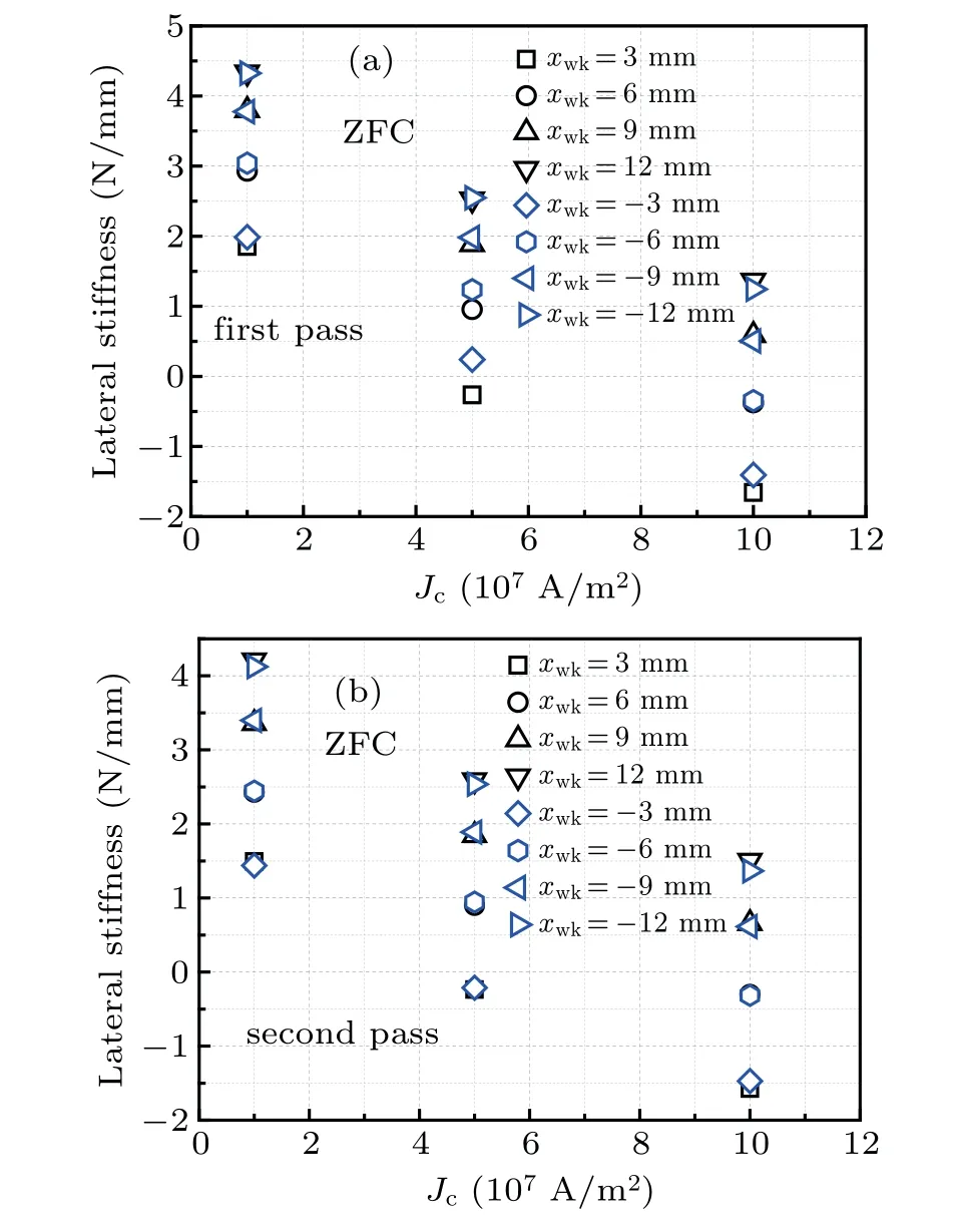
Fig. 6. Values of kxx as a function of Jc at different lateral displacements under the ZFC condition in(a)the first pass and(b)the second pass.
In the FC condition, theJc-dependentkxxvalues in the first and second passes of the PM are shown in Figs.8(a)and 8(b),respectively. Figure 9 shows the lateral force curves with some minor loops at three differentJcvalues in the FC case.In the first pass of the PM, thekxxatxwk=3 mm or 6 mm slightly changes withJcincreasing from 1.0×10⁷A/m2to 10.0×10⁷A/m2, but thekxxatxwk=-3 mm first decreases and then increases for the same change ofJc. The behaviors ofkxxcan be explained from Fig. 9. Although the derivative increases atxwk=3 mm or 6 mm on the major loop asJcincreases from 1.0×10⁷A/m2to 10.0×10⁷A/m2, the minor loops deviate more evidently from the major loops underJc=1.0×10⁷A/m2and 5.0×10⁷A/m2than that underJc=10.0×10⁷A/m2.These changes of the minor loops at the two lateral positions cause the value ofkxxto have a small change under the threeJcvalues in the first pass of the PM.Atxwk=-3 mm, very minor loop under differentJcvalues deviates from the corresponding major loop due to the sensitiveness of the bulk HTS to the PM movement history. The largest slope of the minor loops is produced whenJc=1.0×10⁷A/m2,followed byJc=10.0×10⁷A/m2, and the smallest one is produced whenJc=5.0×10⁷A/m2. Therefore, thekxxatxwk=-3 mm first decreases and then increases withJcincreasing from 1.0×10⁷A/m2to 10.0×10⁷A/m2in the first pass of the PM.At the other lateral positions(such asxwk=9,12,-6,-9,and-12 mm),thekxxdecreases monotonically asJcincreases from 1.0×10⁷A/m2to 10.0×10⁷A/m2.
As shown in Fig. 8(b), in the second pass of the PM,at small lateral displacements (such asxwk=±3 mm and±6 mm), thekxxsignificantly decreases asJcincreases from 1.0×10⁷A/m2to 5.0×10⁷A/m2, but it slightly increases or decreases withJcfurther increasing. At large lateral displacements(such asxwk=±9 mm and±12 mm), thekxxalmost decreases linearly asJcincreases from 1.0×10⁷A/m2to 10.0×10⁷A/m2. Like the case in the first pass of the PM,the reasons for thekxxresults under differentJcvalues can also be understood by analyzing the slopes of the minor loops in Fig.9. In addition,as shown in Figs.8(a)and 8(b),all lateral stiffness values are positive in the two passes of the PM.This means that the lateral levitation of the system is always stable under differentJcvalues in the FC case.
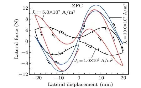
Fig. 7. Lateral forces under different Jc values with minor loops laterally sized at 0.2 mm in the ZFC case.
Although none of the lateral stiffness values at all lateral positions always exhibits the absolute decreasing tendency in the FC case(Fig.8),the largest lateral stiffness is almost produced byJc=1.0×10⁷A/m2at eachxwkwhether in the first or in the second pass of the PM when comparing the results ofkxxunder differentJcvalues in ZFC (Fig. 6). The calculated results in Figs.6 and 8 show that asJcof the bulk HTS becomes large, thekxxat eachxwkgenerally decreases under both the ZFC condition and the FC condition although the lateral force roughly increases(Figs.7 and 9).This extraordinary phenomenon originates from the case that the minor loops deviate from the major loops,which is caused by the strong magnetic hysteresis effect asJcdecreases.
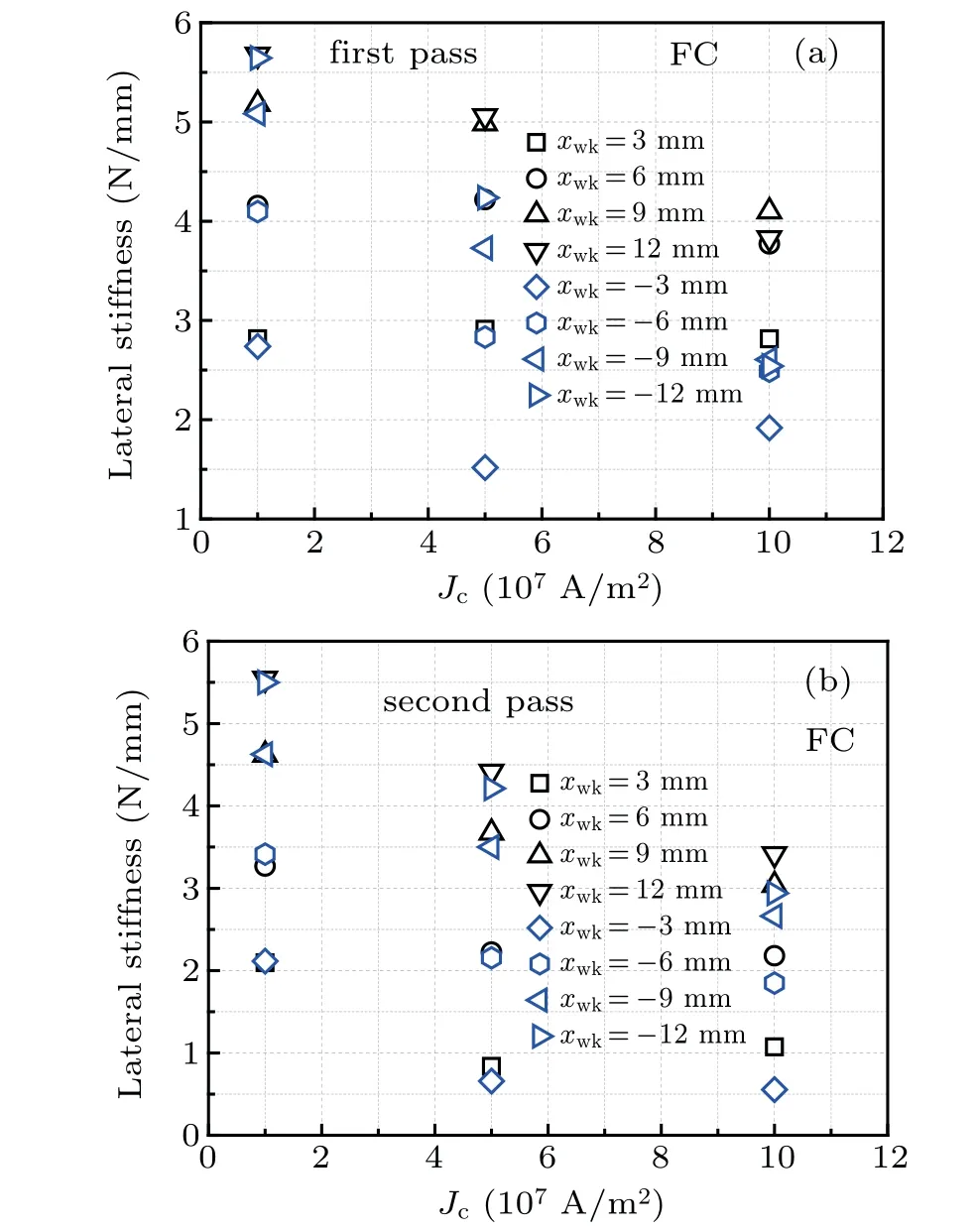
Fig. 8. Values of kxx as a function of Jc at different lateral displacements under the FC condition in(a)the first pass and(b)the second pass.

Fig. 9. Lateral forces under different Jc values with minor loops laterally sized at 0.2 mm in the FC case.
3.3. Effect of PM-to-HTS area ratio
Figures 10(a) and 10(b) show the relationships between the calculatedkxxand the PMtoHTS area ratioαat different lateral positions under the ZFC condition in the first and second passes of the PM, respectively. The differentαvalues are produced by changing the PM cross-sectional area. Asαchanges from 0.5 to 2.0,the magnetic pole face of the PM remains square in shape and the dimensions of the bulk HTS remain constant. Asαincreases from 0.5 to 1.0, thekxxvalues at different lateral positions display different characteristics. At small lateral displacements (such asxwk=±3 mm),thekxxdecreases quickly withαincreasing from 0.5 to 1.0.At medium lateral displacements,thekxxslightly decreases(atxwk=±6 mm)or increases(atxwk=±9 mm)withαincreasing from 0.5 to 1.0. However, at large lateral displacements(such asxwk=±12 mm), thekxxincreases significantly withαincreasing from 0.5 to 1.0. The results ofkxxcan be understood from Fig. 11, where the lateral force curves with some minor loops at three differentαvalues in the ZFC case are plotted. Because all minor loops almost coincide with the corresponding major loops for three differentαvalues,the lateral stiffness at anyxwkis generally equal to the negative derivative at the same point on the corresponding major loop. As shown in Fig.11,since the lateral force curve forα=1.0 is steeper atxwk=3 mm than that forα=0.5,the derivative of the corresponding major loop forα=1.0 is larger than forα=0.5 at the same point whether in the first or in the second pass of the PM. But the lateral stiffness values atxwk=3 mm forα=0.5 and 1.0 are negative. Therefore, the lateral stiffness at the point decreases withαincreasing from 0.5 to 1.0. For the other lateral positions,the characteristics ofkxxcan also be explained by analyzing the shapes of the lateral force curves.As seen from Fig.10,thekxxat each lateral position decreases withαincreasing from 1.0 to 2.0 in the two passes of the PM.Therefore,thekxxvalue forα=1.0 is the largest in the threeαvalues atxwk=±12 mm,but thekxxdecreases monotonically atxwk=±3 mm asαincreases from 0.5 to 2.0. This means that thekxxvalues withαat differentxwkvalues exhibit the absolutely different features.

Fig. 10. Relationships between kxx and PM-to-HTS area ratio at different lateral displacements under the ZFC condition in(a)the first pass and(b)the second pass.

Fig.11. Lateral forces under different PM-to-HTS area ratios(α)with minor loops laterally sized at 0.2 mm in ZFC.

Fig. 12. Relationships between kxx and PM-to-HTS area ratio at different lateral displacements under the FC condition in(a)the first pass and(b)the second pass.
Under the FC condition, thekxxvalues as a function ofαat different lateral positions are shown in Fig. 12. In the first pass of the PM(Fig.12(a)),thekxxforα=1.0 is generally the largest in the threeαvalues at small lateral displacements (such asxwk=±3 mm and±6 mm), but thekxxincreases monotonically at large lateral displacements (such asxwk=±9 mm and±12 mm)asαincreases from 0.5 to 2.0. In the second pass of the PM(Fig.12(b)),thekxxforα=1.0 is generally the largest in the threeαvalues atxwk=±6 mm and±9 mm,but thekxxdecreases monotonically atxwk=±3 mm and increases monotonically atxwk=±12 mm asαincreases from 0.5 to 2.0. The different characteristics ofkxxin the FC condition can be understood from Fig.13,which displays the lateral force curves with some minor loops under differentαvalues.Although all minor loops almost coincide with the corresponding major loops for three differentαvalues,the shapes of the lateral force curves are significantly influenced byα.Like the analysis method under the ZFC case in this section,the above-mentioned features of the lateral stiffness in the FC case can be understood by studying the derivatives at these lateral positions on the major loops for differentαvalues.
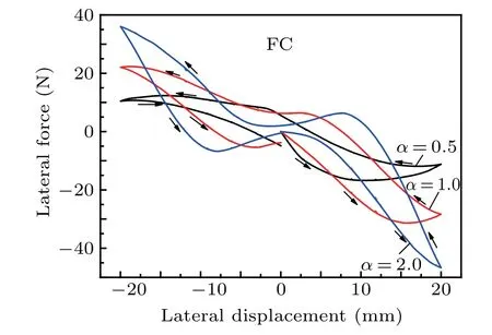
Fig.13. Lateral forces under different PM-to-HTS area ratio(α)values with minor loops laterally sized at 0.2 mm in FC.
3.4. Effect of PM-to-HTS thickness ratio
In Figs. 14(a) and 14(b), the dependence ofkxxon the PMtoHTS thickness ratio(β=hPM/HSC)under the ZFC condition, in the first and second passes of the PM, is plotted,respectively. The different values ofβare obtained by changing the PM thickness, while the dimensions of the bulk HTS remain constant. In addition, the PM surface dimensions andB0also remain constant. Whether in the first or in the second pass of the PM,thekxxat each lateral position decreases withβincreasing from 0.5 to 2.0. The sign ofkxxis always minus at small lateral displacements (such asxwk=±3 mm)for differentβvalues, which means that the lateral levitation of the system is unstable at these working points in the ZFC case. However, the sign ofkxxalways is plus at large lateral displacements(such asxwk=±9 mm and±12 mm)for anyβvalue.Thus,the system is laterally stable at these positions.Atxwk=±6 mm,the sign ofkxxchanges from plus to minus asβincreases from 0.5 to 2.0.These phenomena can be understood from Fig.15,which shows the lateral force curves with some minor loops under differentβvalues in the ZFC case. Owing to the large magnetic hysteresis effect,most of the minor loops are separate from the major loop forβ=0.5. Although the derivatives of the major loop atxwk=±6 mm forβ=0.5 have positive values, the slopes of the minor loops have negative values because the orientations of the minor loops are different from the tangent lines of the major loop at the same points.Therefore,the lateral stiffness is positive whenxwk=±6 mm andβ=0.5. Because the minor loops coincide with the corresponding major loop atxwk=±6 mm forβ=2.0, the lateral stiffness values are deduced from the derivatives of the major loop and have negative values. This leads to the phenomenon of sign switching for thekxxatxwk=±6 mm asβincreases from 0.5 to 2.0. Obviously, the lateral force curve forβ=0.5 is the steepest in the three lateral force curves and the minor loops evidently deviate from the large loop for the sameβ. Thus,thekxxforβ=0.5 at large displacements(such asxwk=±9 mm and±12 mm) has the largest values in the threeβvalues.
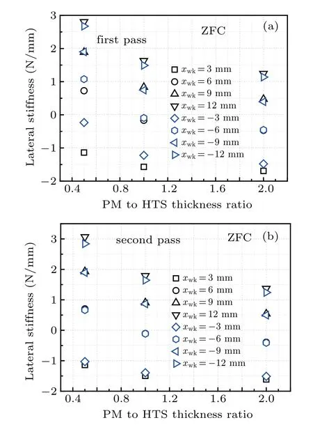
Fig.14. Values of kxx as a function of PM-to-HTS thickness ratio at different lateral displacements under the ZFC condition in(a)the first pass and(b)the second pass.
Figures 16(a) and 16(b) show the dependence ofkxxonβunder the FC condition in the first and second passes of the PM, respectively. Like the ZFC case in this section, thekxxat each lateral position also decreases withβincreasing from 0.5 to 2.0 whether in the first or in the second pass of the PM.All lateral stiffness values are positive no matter howβandxwkchange in the two passes of the PM. This means that the lateral levitation of the system is stable at eachxwkfor anyβvalue in the FC case. Figure 17 shows the lateral force curves with some minor loops under differentβvalues in the FC case.We observe that the steepest lateral force curve is produced forβ=0.5,followed byβ=1.0,and the last one is produced forβ=2.0. In addition,the minor loops clearly deviate from the major loop forβ=0.5. These characteristics of the lateral force curves with the minor loops cause thekxxat eachxwkto decrease asβincreases from 0.5 to 2.0.

Fig.15. Lateral forces under different PM-to-HTS thickness ratio(β)values with minor loops laterally sized at 0.2 mm in the ZFC case.
As seen from Figs. 15 and 17, the shape change of the lateral force curve is more obvious asβvaries from 0.5 to 1.0 than that asβincreases from 1.0 to 2.0. Therefore,thekxxat each lateral position decreases more rapidly whenβchanges from 0.5 to 1.0 than whenβincreases from 1.0 to 2.0(Figs.14 and 16).
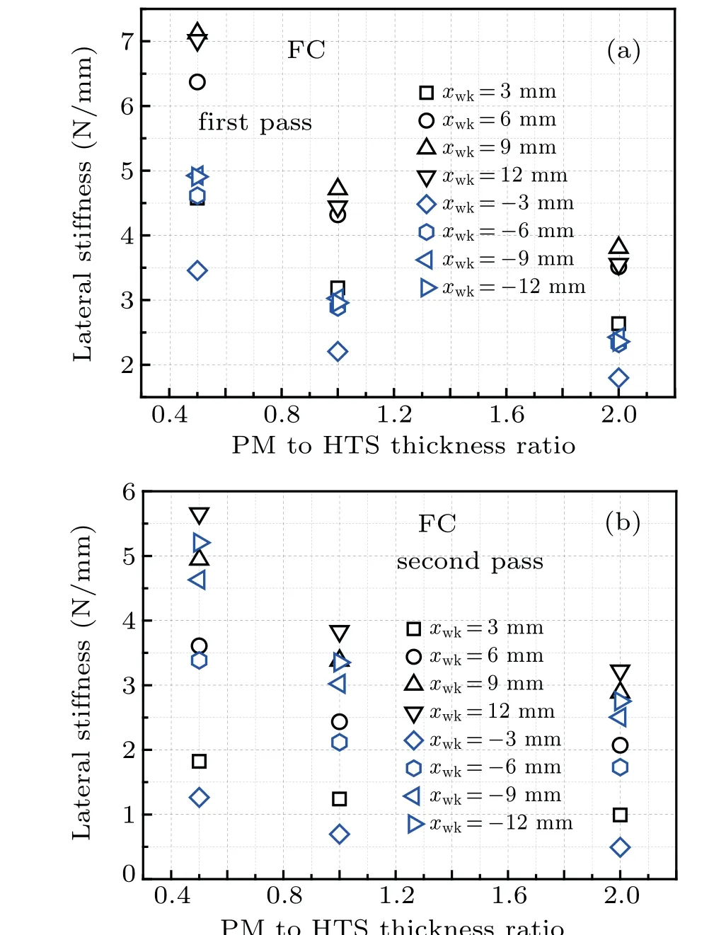
Fig.16. Values of kxx as a function of PM-to-HTS thickness ratio at different lateral displacements under the FC condition in(a)the first pass and(b)the second pass.

Fig.17. Lateral forces under different PM-to-HTS thickness ratio(β)values with minor loops laterally sized at 0.2 mm in FC.
4. Conclusions
By using theTmethod,Bean model,and analytic expressions of the magnetic field produced by a rectangular PM,[34]the lateral force is obtained from an FEM.The average lateral stiffness of a certain minor loop is equal to its negative slope value. The lateral size of the minor loop (Δx) changes from 0.1 mm to 2 mm. By using the linear extrapolation and at the same time by applying all average lateral stiffness values produced by the minor loops with different lateral sizes, the approximate value with a zero traverse for the lateral stiffness is gained. We also study the effects of theB0of the PM,Jc,α,andβon the lateral stiffness at different lateral positions in the first and second passes of the PM under ZFC and FC conditions.The conclusions and unexpected results are summarized as follows:
(i) At most lateral positions (exceptxwk=±3 mm and±6 mm in the ZFC case), the lateral stiffness increases with the increase ofB0in the two passes of the PM under the ZFC and FC conditions. In the ZFC case or at relatively high cooling height, the lateral stability at some lateral positions(such asxwk=±6 mm)can be changed from unstable state to stable state as the PM magnetic field (in other words,B0) becomes strong enough.
(ii) In the ZFC case, the lateral stiffness almost decreases linearly withJcincreasing from 1.0×10⁷A/m2to 10.0×10⁷A/m2at each lateral position whether in the first or in the second pass of the PM.In the FC case,although the lateral stiffness at each lateral position does not always exhibit the absolute decreasing features withJcincreasing,the largest lateral stiffness is generally produced by the minimum value ofJc. The unexpected results indicate that although the lateral force essentially increases,the lateral stiffness decreases asJcimproves.
(iii)Theα-dependent lateral stiffness changes with some parameters, which includes cooling conditions of the bulk HTS,lateral displacement,and movement history of the PM.
(iv)In ZFC and FC conditions,the lateral stiffness at each lateral position decreases withβincreasing from 0.5 to 2.0 whether in the first or in the second pass of the PM.Moreover,the lateral stiffness decreases more rapidly withβincreasing from 0.5 to 1.0 than from 1.0 to 2.0.
猜你喜欢
社会科学战线(2022年8期)2022-10-25
Chinese Physics B(2021年10期)2021-10-28
力学与实践(2021年4期)2021-08-30
Chinese Physics B(2021年4期)2021-05-06
无线互联科技(2020年1期)2020-03-23
甘肃农业(2019年10期)2019-12-03
科学与财富(2018年7期)2018-05-21
装备制造技术(2018年12期)2018-02-26
哈尔滨工程大学学报(2017年3期)2017-04-08
水利与建筑工程学报(2015年1期)2015-08-12

- Chinese Physics B的其它文章
- Projective representation of D6 group in twisted bilayer graphene*
- Bilayer twisting as a mean to isolate connected flat bands in a kagome lattice through Wigner crystallization*
- Magnon bands in twisted bilayer honeycomb quantum magnets*
- Faraday rotations,ellipticity,and circular dichroism in magneto-optical spectrum of moir´e superlattices*
- Nonlocal advantage of quantum coherence and entanglement of two spins under intrinsic decoherence*
- Universal quantum control based on parametric modulation in superconducting circuits*