
Dynamics of plasma bullets by nanosecond pulsed micro-hollow cathode discharge within air
2021-08-05 08:29PeizhenLI李佩贞ZhengchaoDUAN段正超TianliangZHANG张天亮FengHE何锋RuoyuHAN韩若愚andJitingOUYANG欧阳吉庭
Plasma Science and Technology 2021年8期
Peizhen LI(李佩贞),Zhengchao DUAN(段正超),Tianliang ZHANG(张天亮),Feng HE (何锋), Ruoyu HAN (韩若愚) and Jiting OUYANG (欧阳吉庭)
School of Physics, Beijing Institute of Technology, Beijing 100081, People's Republic of China
Abstract In this paper, the air plasma jet produced by micro-hollow cathode discharge (MHCD) is investigated.The discharge is powered by a positive nanosecond pulse high voltage supply.The waveforms of the discharge, the images of the jet, the evolution of the plasma bullet and the reactive species are obtained to analyze the characteristics of the MHCD plasma jet.It is found that the length of the plasma jet is almost proportional to the air flow rate of 2–6 slm.Two plasma bullets appear one after another during a single period of the voltage waveform,and both of the two plasma bullets are formed during the positive pulse voltage off.The propagation velocity of the two plasma bullets is on the order of several hundred m/s,which is approximate to that of the air flow.These results indicate that the gas flow has an important influence on the formation of this MHCD plasma jet.
Keywords: air plasma jet, plasma bullets, micro-hollow cathode discharge, nanosecond pulse
1.Introduction
The atmospheric pressure plasma jets (APPJs) are generated in an open environment rather than in an air tight vessel [1].In APPJs, a low-temperature, non-equilibrium plasma with abundant reactive nitrogen species (RNS) and reactive oxygen species(ROS)can be transferred away from the discharge region, which is suitable for the application in surface modification [2–4], biomedical engineering [5–8], nanomaterial preparation [9, 10] and many other fields.During last two decades, APPJs became a hot topic of low-temperature plasma, and attracted more and more attentions.
Various electrode structures are developed to produce APPJs.One kind of APPJ structure is based on dielectric barrier discharge (DBD) [11–17].In DBD jets, at least one electrode is covered by a dielectric layer, and the alternating current (AC) or pulsed power supply can drive the discharge of DBD jets.Another kind of APPJ structure consists of electrode without dielectric layer covering.This APPJ structure includes single needle[18,19],needle-hole[20–24],and micro-hollow cathode[25–27],which can be driven by direct current (DC), AC or pulsed power supply.
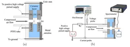
Figure 1.(a) Cross-sectional scheme of the micro-hollow cathode structure and (b) diagram of the experimental system.
Many works have been devoted to study the characteristics of APPJs,especially about the development mechanism of the plasma jet generated by AC or pulsed power supply.In many researches, a moving light emission blob, which corresponds to the ‘plasma bullet’ of APPJs [15], was observed during the jet development.The movement of the light emission blob represents the development of APPJs.With various structures and power supplies, the phenomena of the plasma jet propagation are quite different.Luet al[14, 15]and Hofmanset al[16]drove DBD jets using nanosecond and microsecond pulsed power supply respectively.Zhuet alconducted the DBD jet experiment with kHz AC power supply [17].Their results show that the development of the DBD plasma jet occurs within the current pulse of the discharge, and the peak velocity of jet propagation is about tens of km s−1to hundreds of km s−1.Xionget alalso showed that the plasma jet of single needle structure driven by nanosecond power supplies is formed during the discharge, and the development of the plasma bullet can be on the order of 100 km s−1[19].However, in the self-pulse discharge of needle-hole structure, Xianet alshowed that the plasma jet can be formed after the discharge, and the velocity of the plasma bullet is only about hundreds of ms−1[20, 21].Leiet alobtained similar velocity about the jet propagation [22].DBD jets with the high velocity are operated with noble gas,and the jet is considered as a result of discharge development in the noble gas channel surrounded by air.It is believed that the local electric field in the plasma bullet played an important role in the propagation of the plasma jet.For the jet of slow velocity, air or nitrogen is used as working gas in the experiments.Some research groups considered that the dynamics of the jet depends on the gas flow [21].While Walshet al[23] presented a high velocity air jet with a needle-hole device,which is not consistent with the results of references [20–22].More efforts should be made to understand the propagation mechanism of APPJs under different operating conditions.
Although the MHCD became a promising device to generate APPJ, most of the works concentrate on the temperature of MHCD jet[25,26],the effects of jet treatment[27],etc.Recently, Duanet alpresent some results about the propagation of MHCD jet with helium [28].However,MHCD jet with air is more helpful to obtain RNS and ROS.In this work, an air plasma jet produced by nanosecond pulsed discharge in micro-hollow cathode device is investigated.The characteristics and the propagation of the air plasma jet are studied, and the reactive species generated in the plasma jet are analyzed.
2.Experimental setup
Figure 1(a) shows the structure of the micro-hollow cathode used in this experiment.The structure consists of three parts:a PTFE(Poly tetra fluoroethylene)tube,a ceramic disk and two copper wafers.The two copper wafers are placed in the two grooves of the ceramic disk, forming a typical ‘sandwich’structure of metal-dielectric-metal.The diameter of the two copper wafers is 15 mm and the thickness is 0.8 mm.The diameter of the ceramic disk is 25 mm, and the thickness between the two grooves is 0.8 mm.One of the copper electrodes is grounded through a metal annulus.The thickness of the metal annulus is 1 mm.The two copper wafers are perforated centrally,and the diameter of the hole is 0.6 mm.A hole with diameter of 1.0 mm is drilled through the ceramic disk.This geometry of the discharge device is similar to that used in the reference [28].Figure 1(b) shows the system of the experimental apparatus.The above-mentioned microhollow cathode discharge structure is embedded in the PTFE tube.One side of the PTFE tube is connected to an air pipe and an air compressor.The air compressor provides compressed air for the micro-hollow cathode device, and the gas flow meter controls the air flow rateQ.The copper wafer at the upstream of the air flow is the power electrode, and the copper wafer at the downstream of the air flow is the ground electrode.The power electrode is connected to a positive nanosecond pulsed high voltage supply via a 1.5 kΩ current limiting resistor.The nanosecond pulsed high voltage supply(HVP-15, Xi’an Smart Maple Electronic Technology Co.,Ltd.) can output an adjustable square waveform with the voltage of 0–15 kV, the frequency of 0–100 kHz, and the pulse width of −1 ms.The applied voltage on the power electrode is monitored by a high voltage probe(Tek P6015A).The current is monitored by a current probe (Pearson 2877,Pearson Electronics).The voltage and current waveforms are storaged by a digital oscilloscope (DPO 4034B, Tektronix).Both of time-integrated and time-resolved images of the plasma jet are acquired by an intensified charge-coupled device(ICCD)camera(iStar DH334T,Andor)with real time mode and kinetic series mode respectively.In real time acquisition mode, the images acquired with ICCD are only determined by the optical signal input during the exposure time of CCD.In kinetic series acquisition mode, the images acquired with ICCD are controlled by the gate width of electronic gater and the exposure time of CCD.The ICCD camera is triggered by the discharge current.A fiber is placed about 2 mm away from the orifice of the metal annulus and perpendicular to the jet to guide the light into a spectrometer(Avaspec-ULS3648, Avantes).The optical emission spectra(OES) is measured using the spectrometer which has four gratings (200–315 nm, UE-2400 lines mm−1; 315–365 nm,UF-3600 lines mm−1; 365–460 nm, VE-2400 lines mm−1;460–1000 nm, NB-600 lines mm−1).The resolutions of the four channels are 0.07–0.09 nm,0.05–0.06 nm,0.07–0.09 nm and 0.3–0.369 nm, respectively.The focal length is 75 mm.
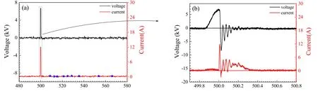
Figure 2.(a) The voltage and current waveforms, the asterisks on the current waveform correspond to the moments at which the images in figure 4(a) are captured, (b) waveforms during the voltage pulse. Vamp=6700 V, f=2 kHz, tw=300 ns, Q=3 slm.
3.Results and discussion
3.1.Characteristics of the nanosecond pulsed discharge
Figure 2 presents the typical current and voltage waveforms of the micro-hollow cathode discharge.The waveform magnified during the pulse of the applied voltage is shown in figure 2(b).The pulse widthtwand frequencyfof the pulse voltage are 300 ns and 2 kHz respectively.The air flow rateQis 3 slm.Figure 2(b)indicates that the maximum value of the pulse voltage is about 6700 V and the rising edge of the pulse voltage is about 100 ns.Compared with the rising edge of the pulse voltage, the rising edge of the current has a delay time of about 130 ns.After breakdown occurs in the electrode gap,the current rises rapidly to 12 A in about 9 ns;meanwhile,the voltage on the power electrode drops towards 0 kV.The duration of the first pulse current is about 20 ns, then the current oscillates around 3 A until the falling edge of the pulse voltage.The low voltage and large discharge current between the electrodes indicate that the discharge turns into arc regime after it is ignited.
3.2.Length of the plasma jet
Using this micro-hollow cathode discharge, an air plasma jet is generated.Figure 3(a) presents the luminous images of the plasma jets at different air flow rates.The images are captured by ICCD camera in real time mode, and the CCD exposure time of the ICCD camera is set to be 0.1 s.Therefore the figure 3(a) illustrates the time-integrated images of the MHCD jet.The gray blocks with label ‘C’ in figure 3(a)indicate the position of grounded electrode.The figure 3(b)provides the length of the plasma jet versus the air flow rate.The lengths of the plasma jet are measured from the time integral images taken by the ICCD camera.Figure 3(a)shows that the length of the plasma jet increases with the increase of the air flow rate.When the air flow rate is 2 slm,the length of the plasma jet is about 1.2 mm.When the air flow rate is increased to 6 slm, the length of the plasma jet can reach 3.7 mm.The curve in figure 3(b)shows that,the length of the plasma jet increases almost linearly with the increase of air flow rate.Figure 3(a)also presents that the luminous intensity of the plasma jet becomes stronger at a higher air flow rate.The peak intensity is increased by about 2 times.These results indicate that the air flow rate has an effect on the plasma jet.
During the voltage pulse, the discharge is ignited in the gap between two electrodes, and a plasma blob is generated.After the falling edge of the short voltage pulse,due to airflow the plasma blob travels out of the gap to form the plasma jet.The recombination and radiative transition occur in the plasma blob,so the plasma density in the plasma jet decreases and the luminosity finally disappears.However,at higher gas flow rate, more particles will be driven out of the electrode gap and travel longer distance.Therefore, the length and the intensity of the plasma jet increase with the air flow rate.
3.3.Propagation of the plasma jet
Although the effect of the gas flow on the jet length is similar to that of DBD or other structures, the jet propagation of this MHCD has some different characteristics.The propagation of MHCD jet is represented by the time-resolved optical images of the plasma jet.The ICCD is triggered by the signal converted from the discharge current at 8.5 A.Therefore,the start timet0=0 for all the time-resolved images is the moment when the current reaches 8.5 A.In order to observe the image before the discharge,a delay of 499 μs is applied to the gater of ICCD.The frequencyfof the power supply is 2 kHz,so the period is 500 μs.It means that the acquisition of each timeresolved image is postponed to the next discharge pulse.The gate width and the exposure time of ICCD are set to be 1 μs and 0.1 s,respectively.Each image is the accumulation of the light signal in 10 discharge pulses with the same delay time and same gate width.The parameters of the pulse voltage are the same as in section 3.2.Figure 4(a) shows the timeresolved optical images of the plasma jets at the air flow rateQ=3 slm.The time point recording each image is labeled by an asterisk ‘★’ in figure 2(a).Figure 4(a) shows that at 507.3 μs,a very faint luminous region appears at the orifice of the micro-hollow cathode.After 5 μs, the light-emitting region propagates about 0.6 mm along the axis, forming a‘bullet-like’ jet.During this time, the light-emitting region becomes larger and the luminous intensity becomes stronger.The images of 515.3 μs and 519.3 μs show that the lightemitting region moves forward further and the luminous intensity becomes weak.Although the intensity decreases,this plasma bullet can be observed until 524.3 μs.
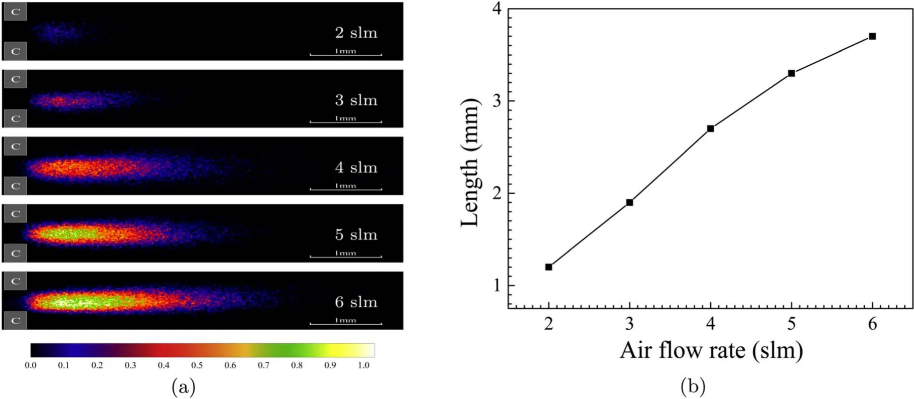
Figure 3.(a) The luminous images of the plasma jets.(b) The curve of the jet length versus the air flow rate. Vamp=6700 V, f=2 kHz,tw=300 ns.
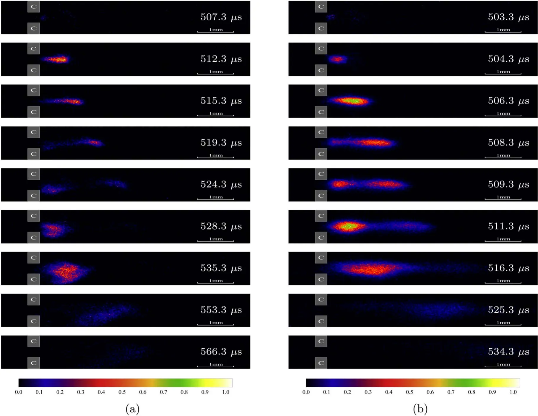
Figure 4.Propagation images of the plasma jets.(a) 3 slm, (b) 6 slm. Vamp=6700 V, f=2 kHz, tw=300 ns.
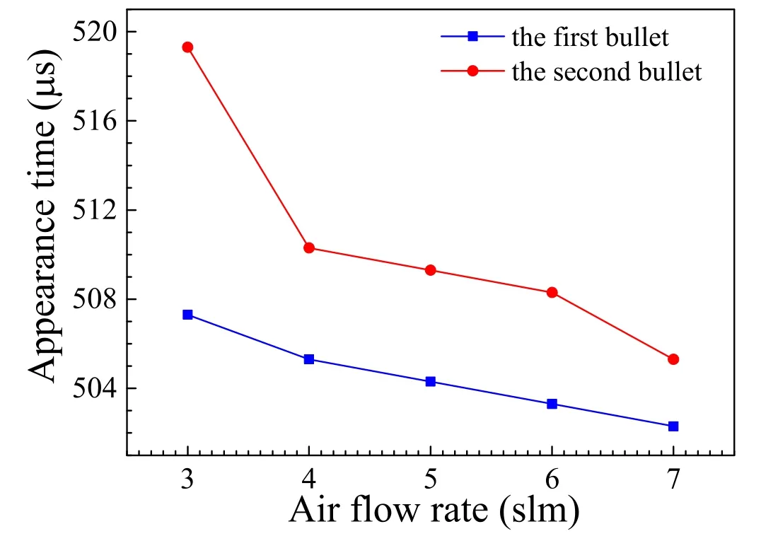
Figure 5.Appearance time of the plasma bullet versus air flow rate.Vamp=6700 V, f=2 kHz, tw=300 ns.
It can be found that att=519.3 μs, a new light-emitting region appears near the cathode orifice.This region reflects another plasma bullet of the MHCD jet.The second plasma bullet can be observed more clearly from the images of 524.3–566.3 μs.During this period, the second plasma bullet becomes larger and brighter gradually, while the first plasma bullet almost disappears at 528.3 μs.The second plasma bullet continues to propagate forward until 566.3 μs.
The phenomena of two jet bullets have been observed at different air flow rates.The time-resolved images of 6 slm are shown in figure 4(b).The development process of the jet bullets in figure 4(b) is similar to that of 3 slm.Comparing the figures 4(a)and(b),it can be found that as the increase of the air flow rate,the luminous intensity becomes stronger and the plasma bullets develop farther along the axis.While the duration of the plasma jet becomes shorter as the air flow rate increases.The air flow rate increases from 3 to 6 slm, but the duration of the plasma jet decreases from 59 to 31 μs.Figure 5 shows the appearance times of the first and second bullets versus the air flow rate.It can be seen that the appearance time of the plasma jet is advanced with the increase of the air flow rate.When the air flow rate is 3 slm,the first and second plasma bullets appear at 507.3 μs and 519.3 μs, respectively.Compared with the results of 3 slm,the appearance time of the first and second plasma bullets at 6 slm is advanced by about 4 μs and 11 μs respectively.The trends of appearance time of the two plasma bullets with the air flow rate are almost similar.
3.4.Velocities of the plasma bullets
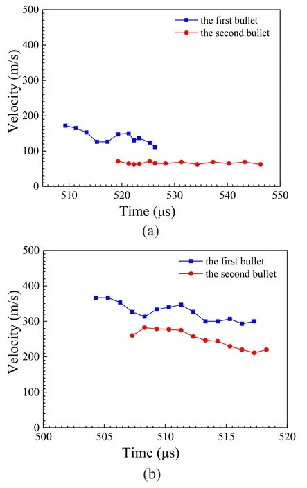
Figure 6.Velocity of the plasma jet versus time.(a)3 slm,(b)6 slm.Vamp=6700 V, f=2 kHz, tw=300 ns.
Based on the time-resolved images,the propagation velocities of the two plasma bullets are estimated from the front of the bullet at different times.The velocity of the bullet versus time is shown in figure 6.The result shows that the velocity of the first plasma bullet is higher than that of the second bullet,but both velocities of the two bullets increase with the air flow rate.When the air flow rate is 3 slm, the velocity of the first bullet is about 150 m s−1,and the velocity of the second bullet is about 70 m s−1.When the air flow rate is 6 slm,the velocity of the first bullet increases to approximately 330 m s−1, and the velocity of the second bullet increases to 250 m s−1.Considering that the jet will pass through the metal annulus of 1 mm thickness, relative to the voltage pulse, the appearance time of the first plasma bullet atQ=3 slm and 6 slm is delayed about 7 μs and 3 μs, respectively.This is consistent with the results of figure 5.
The gas velocity of air flowvis estimated according to the formulav=4Q/(π·d2),whereQis the air flow rate,dis the diameter of the center hole of the copper wafer(d=0.6 mm in our experiment).When the air flow rates are 3 slm and 6 slm,the air flow velocities are approximately 177 and 354 m s−1.From the curves in figure 6,it can be seen that the propagation velocity of the first plasma bullet is close to the value of the air flow velocity.The propagation and velocity of the plasma bullet further confirmed that the gas flow has an important influence on the dynamics of the microhollow cathode plasma jet.
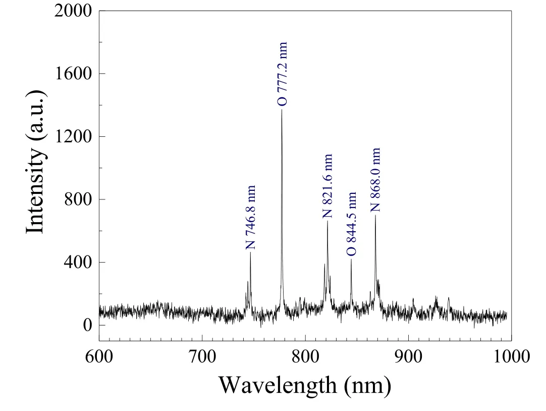
Figure 7.Emission spectrum of the plasma jet outside the cathode hole. Vamp=6700 V, f=2 kHz, tw=300 ns.The air flow rate is 6 slm.
3.5.Development of the reactive species
In this experiment, the optical emission spectrum is used to identify the reactive species generated in the plasma jet.The emission spectrum of the plasma jet outside the cathode hole is shown in figure 7.The spectral lines mainly locate in 700–900 nm,and indicate that the dominating reactive species in the plasma jet are oxygen atoms and nitrogen atoms.The maximum intensity is emitted by oxygen at 777.2 nm.
The propagation of reactive species during the development of the plasma jet is also investigated.Figure 8 shows the time-resolved images of 777.2 nm and 844.5 nm lines taken by ICCD camera with filters.The full width at half maximum of the filters is 10 nm.Each image is obtained by the ICCD camera accumulated 100 times at the same delay time with 1500 ns gate width.The air flow rate is 6 slm.
From the images in figure 8, it can be seen that the appearance time of the two reactive species at the orifice is 503.3 μs,which exactly corresponds to that of the first plasma bullet in figure 4(b).The excited oxygen atoms of 777.2 and 844.5 nm are long-lived particles whose lifetime is about a few tens of microseconds in non-thermal plasma[29].During 503–508 μs, the reactive species move forward, just like the propagation of the first plasmas bullet shown in figure 4(b).Then more reactive species emerge again at the orifice of the electrode hole.The movement of these reactive species corresponds to the second bullet.
3.6.Discussion
The experimental results mentioned above show that two plasma bullets of the MHCD air jet are observed during one cycle of the voltage waveform, and the images of the two plasma bullets are captured after the discharge.It has been noted in section 3.1 that the discharge of this MHCD transfers into arc regime.During the pulse current, the voltage drop between the plasma and the grounded electrode is too small to sustain a discharge out of the grounded electrode.The width of pulse voltage is only 300 ns.The falling edge of the pulse voltage, also the falling edge of the pulse current, locate at around 500.3 μs.The voltage drop should be zero during the development of the plasma bullets after 500.3 μs.Therefore,the plasma bullets of MHCD do not propagate during the pulse of discharge current with a large voltage drop.This is very different from the jets of DBD [15, 17] or needle-hole glow jet [23].Furthermore, the velocity of the two plasma bullets is close to that of air flow, which is about two orders lower than the propagation velocity of DBD jets[15,17],and the air flow rate has a great influence on the appearance time of the plasma bullets.In the OES, the spectral lines of,which are usually found in air discharge [24], were not observed in our experiments.All the results show that, it is not the electric field but the air flow plays an crucial role in the development of the two plasma bullets.Produced by the discharge, the long-lived particles moving with the airflow form the MHCD jet.
According to the appearance time shown in figure 5, it can be considered that the first plasma bullet is generated by the particles moving with the air flow after the discharge plasma reaches the cathode.The arc discharge forms a narrow plasma channel, which causes lots of long-lived species confined in this channel.The input power during the discharge is rather high with a peak value of 50 kW.The gas temperature increases dramatically, which causes the gas plasma to expand towards both downstream and upstream.The gas plasma towards downstream forms the first jet bullet.The gas plasma towards upstream will flow out of the gap after a time interval, which forms the second jet bullet.This time interval also depends on the gas flow rate.Therefore,the second jet atQ=6 slm appears earlier than atQ=3 slm, as shown in figure 4.
4.Conclusion
In this work, the characteristics of plasma jet are studied experimentally.Using air as working gas, the MHCD driven by a nanosecond pulse supply generates plasma jets.The discharge waveforms,the jet length,and the OES are obtained and analyzed.It is found that during the development of the plasma jet,two plasma bullets are observed during one period of the voltage waveform.Both of the two plasma bullets are formed after the falling edge of the positive pulse voltage.The appearance time of the plasma bullets advances with the increase of air flow.The velocity of the two bullets is very close to that of the air flow.The development of reactive species in the plasma jet also corresponds to the propagation of the two bullets.These results indicate that the gas flow has a crucial influence on propagation of this MHCD plasma jet.
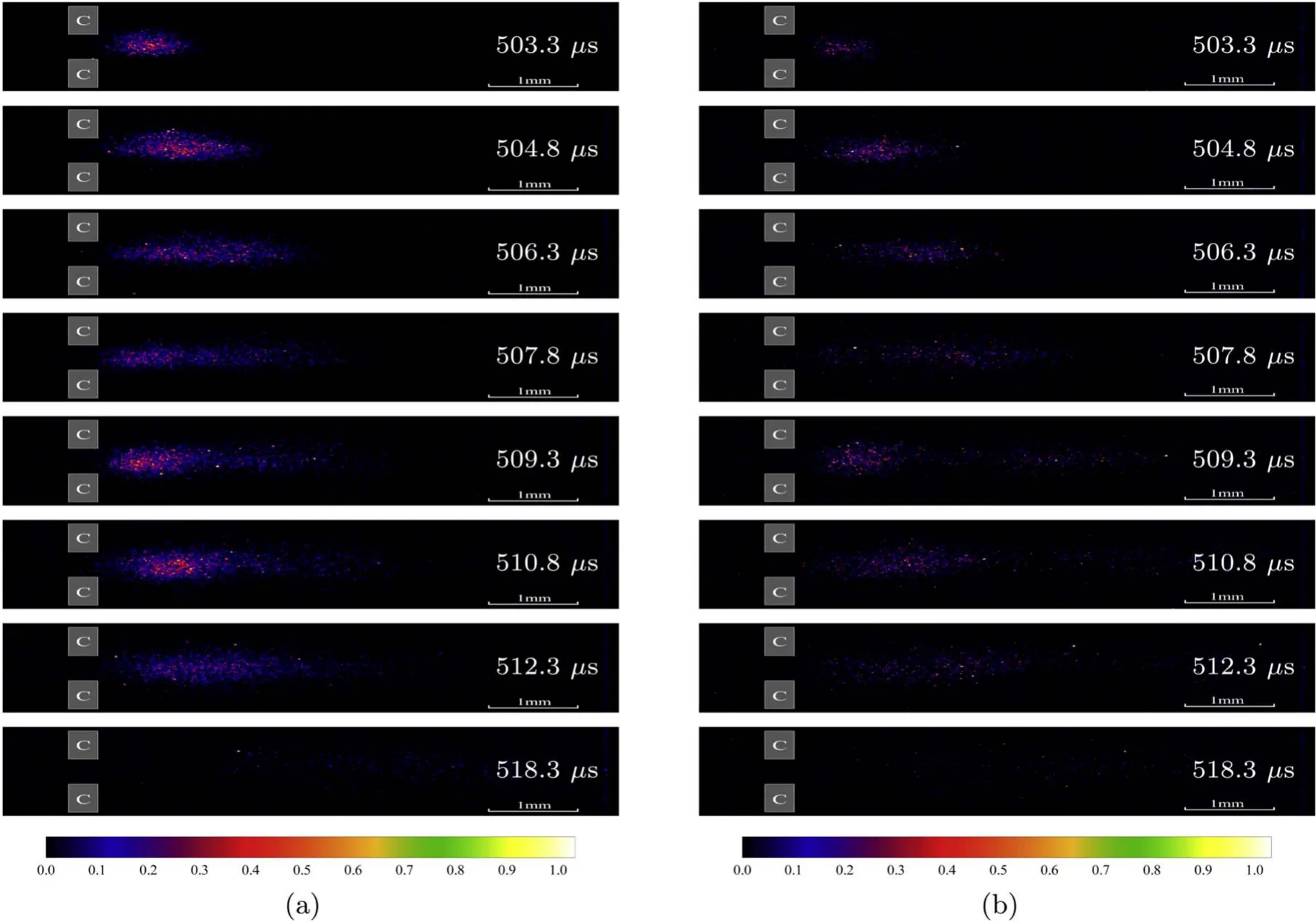
Figure 8.Time-resolved images of reactive species.(a) 777.2 nm, (b) 844.5 nm. Vamp=6700 V, f=2 kHz, tw=300 ns.The air flow rate is 6 slm.
Acknowledgments
This work was supported by National Natural Science Foundation of China (No.11 475 019).
ORCID iDs
猜你喜欢
幼儿教育·父母孩子版(2022年2期)2022-03-12
故事作文·低年级(2021年2期)2021-02-04
故事作文·低年级(2021年2期)2021-02-04
作文大王·低年级(2020年12期)2020-12-31
中华诗词(2019年9期)2019-05-21
思维与智慧·上半月(2018年4期)2018-04-09
时代青年(上半月)(2017年6期)2017-06-10
青春(2017年5期)2017-05-22
美与时代·城市版(2016年9期)2016-05-14
小资CHIC!ELEGANCE(2015年12期)2015-09-10
 Plasma Science and Technology2021年8期
- Plasma Science and Technology的其它文章
- Two-point model analysis of SOL plasma in EAST
- Line identification of boron and nitrogen emissions in extreme- and vacuumultraviolet wavelength ranges in the impurity powder dropping experiments of the Large Helical Device and its application to spectroscopic diagnostics
- Landau damping of twisted waves in Cairns distribution with anisotropic temperature
- Effects of magnetic field on electron power absorption in helicon fluid simulation
- Dependence of plasma structure and propagation on microwave amplitude and frequency during breakdown of atmospheric pressure air
- Machine learning application to predict the electron temperature on the J-TEXT tokamak