
Investigation of variable aperture on the performance and lifetime of ion thruster
2021-10-31 08:14JuanjuanCHEN陈娟娟YanhuiJIA贾艳辉HaiGENG耿海NingGUO郭宁andDezhouGUO郭德洲
Plasma Science and Technology 2021年10期
Juanjuan CHEN (陈娟娟), Yanhui JIA (贾艳辉), Hai GENG (耿海),Ning GUO (郭宁) and Dezhou GUO (郭德洲)
National Key Laboratory of Vacuum and Cryogenic Technology on Physics,Lanzhou Institute of Physics,Lanzhou 730030, People’s Republic of China
Abstract Beam flatness is an important parameter that determines the performance and the lifetime of a gridded ion thruster.To improve the beam flatness of the 30 cm(LIPS-300)ion thruster,variable aperture ion optics that adapts to the decreasing ion density as the radius increases is proposed.It is the ion optics that the screen grid surface is divided into several zones, where the aperture diameter in each zone is determined by the ion density and the electron temperature upstream of the screen grid.The beam current density in the central area is artificially reduced.A particle in cell-Monte Carlo collision model is applied in this work to investigating the effect of variable aperture on the perveance and the maximum beam current per aperture by simulating the extraction, focusing and acceleration processes of ions.Taking into account the engineering implementability, the screen grid surface is divided into four zones.The hole diameter in each zone is decreased from 1.95 mm to 1.8 mm, 1.9 mm, 1.8 mm and 1.7 mm, respectively.The simulation results show that the maximum ion density in the center area of grid is decreased by 10.6% and 6.99%, while it is increased by 6.49% and 22.3% in the edge region, respectively.The beam flatness of the variable aperture ion optics is improved from 0.69 to 0.88.The erosion rate is decreased by 31.9%, but the total beam current is also decreased by 7.15%.The simulation results can provide a valuable reference of the development of the ion thruster.
Keywords: ion thruster, variable aperture, PIC-MCC, simulation
1.Introduction
Due to its light launch weight,high load ratio,high precision of attitude and orbit control, long on-orbit lifetime, flexible and diverse application modes, and the low launch cost, electric propulsion [1] has become an important indication of the advanced satellite platforms, and is the core technology to support the satellite’s performance improvement and upgrading.Ion thruster [1] has been successfully applied to the satellite’s position maintenance, orbit transfer and other space missions [2].Beam flatness [1], which is defined as the average current density divided by the peak, is used to evaluate the thruster’s performance and predict its lifetime.For an ion thruster, the higher the beam flatness is, the better the performance is.At low beam flatness,which produces the non-uniform current density, seriously affects the performance of the thruster and leads to the occurrence of the discharge sparking.The beam with high current density in the center area of the thruster is overfocused[3]and ions in this area are intercepted on the accel grid,which will make the accel grid current increase.Additionally,the thermal deformation of the grids in the area is intensified because of the high current density,and it increases the risk of the short circuit.On the other hand,the charge exchange(CEX)ions[4–6]that are generated by collision between ions and neutral atoms will sputter away materials from the downstream surface of the accelerator grid.Aperture barrel is enlarged because of the sputtering erosion and there is a hexagonal ‘pits-and-grooves’pattern on the downstream of accel grid surface,which results in the structural failure of the grids if the erosion penetrates through the grid.Serious erosion will terminate the lifetime of the thruster.Therefore, how to improve the beam flatness is a key issue that must to be solved for the development of the ion thruster.
Large numbers of theoretical and experimental studies have been carried out on this problem.In 2005 [7], Jet Propulsion Laboratory studied the influencing factors and the influencing degree of the NSTAR ion thruster’s beam flatness by means of numerical method.Based on the simulation results, they redesigned the magnetic topological structure and magnetic intensity of this thruster and conducted a verified experiment.The experimental result showed that the beam flatness of the new design was raised to 0.68 that was far larger than the original 0.47.The next year the modified method was verified in the 15 cm ion thruster[8],whose beam flatness was improved from 0.683 to 0.736 [9].
Lanzhou Institute of Physics (LIP) is the institute that specializes in the research of ion thrusters in China.After decades of the development, LIP has successively developed a series of engineering products.A 1 kW ion thruster, whose beam flatness was increased from 0.29 to 0.7 [10] by modifying its magnetic field, has already tested on-orbit in 2014[11].The thruster performed well in orbit.Recently, highpower ion thruster [12] becomes a necessity with the advancement of the deep space exploration missions, of which most important problem is to improve the beam flatness to make the thruster work reliably for a long time.In 1995, a variable aperture [13] of the ion grids was proposed by Mr Liu, whose original purpose was to improve the uniformity of the current density by extracting the same ions through different apertures.It was not until in 2018 that LIP attempted to find out the influence of the variable aperture on the beam focusing performance by using a numerical method[14].The simulation results showed that the focus of the ions in the center of the thruster shifted inward and the current density of this area decreased and the diameter of the beam current got small.Conversely, the focal point of the ions in the edge region moved outward, and the density and the diameter of the beam current increased simultaneously.The simulated beam flatness of the 10 cm ion thruster was increased by 28%.
A LIPS-300 ion thruster [15] that is currently being developed by LIP will be applied for the North-South Station Keeping (NSSK) missions of the next-generation communication and all-electric propulsion satellites in 2025.Depending on the mission requirements,the thruster needs to be operated in 23 different modes, meaning that each mode has to be highly reliable.In particular, the thrust of the ion thruster is relatively small, and the thruster must be operated for a longer time.Erosion from high-energy ion’s sputtering and hitting on the accel grid barrel or the downstream surface extremely limits the lifetime of the thruster.Therefore, to reduce the erosion rate, LIPS-300 ion thruster employs a three-grid system and firstly uses variable aperture ion optics.This paper theoretically proposed the concept of the variable aperture ion optics, and then simulated the extracting,focusing and accelerating processes of the beam ions by using particle in cell (PIC)-Monte Carlo collision (MCC) method[16]to analyze the feasibility of the new grid and its effect on the performance and the lifetime of the ion thruster.Finally,the simulation results were compared with the measured ones to verify the correctness and its availability of the design of the variable aperture ion optics.
2.Simulation model
The three-grid system of the LIPS-300 ion thruster is composed of screen grid, accelerator grid (accel grid) [1] and decelerator grid (decel grid) [1].Decel grid is placed downstream of the accel grid and it allows the grid to operate at large negative voltage,with which the grid is more beneficial to reduce the loss of the neutral atoms and improve the mass utilization efficiency.The length of the deceleration field is greatly shortened for the existence of the decel grid,and ions will move in a straight line until the beam current is formed,so that the beam divergence angle is smaller than two-grid system.The schematic diagram is shown in figure 1.
2.1.Calculation domain
Calculation domain is shown in figure 2.The overhead, the profile diagram of grid and the two-dimensional simulation domain are given,in which the black parts represent the grids.Figure 3 shows the boundary conditions of the twodimensional simulation.Only half of the aperture is selected as research objects due to its axisymmetric characteristics.zandrrepresent the axial and radial positions,respectively.Vprefers to the plasma voltage of the discharge chamber.Vsc,VacandVdccorrespond to the voltage of the screen grid, accel grid and decel grid.rsc,racandrdcindicate the aperture radii of the screen grid, accel grid and decel grid, respectively.tsc,tacandtdcare the thickness of these three grids.lsais the gap between the screen and accel grid;ladis the gap between the accel grid and the decel grid.RmaxandZmaxstand for the radial and axial sizes,respectively.Φ is the electric potential.Boundaries included in this simulation are screen grid, accel grid, decel grid, left boundary, right boundary, up boundary and axis of symmetry.Except for reflection in axis of symmetry and up boundary, ions are all absorbed by other boundaries.
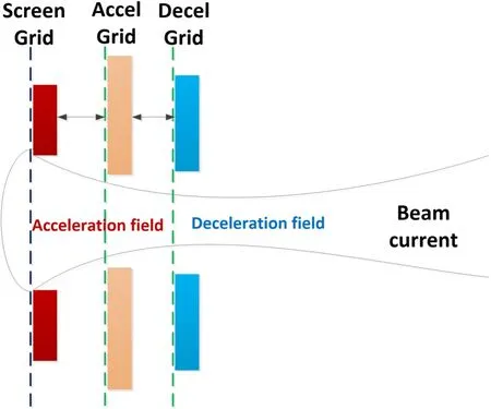
Figure 1.The diagram of three-grid system.
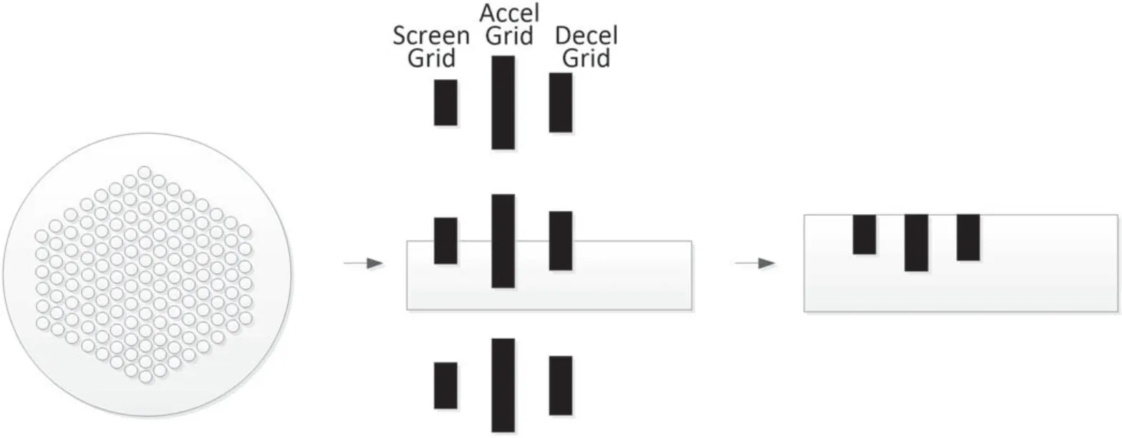
Figure 2.Calculation domain.
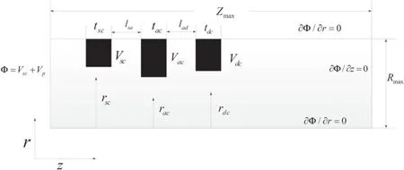
Figure 3.Schematic of the simulation area.
2.2.PIC-MCC model
2.2.1.Flow chart.On the basis of the grid’s geometrical structure and working mechanism, a PIC-MCC simulation model is developed, where PIC model is used to accelerate and track the trajectory of the charged particles, while MCC model deals with the collision between charged particles and neutral atoms.
The functions of the PIC-MCC model are to simulate the process of the ion’s acceleration,focusing and extraction,and to obtain the production of the CEX ions and its sputtering and hitting processes on the acceleration barrel and downstream of the accel grid surface.
Figure 4 shows the flow chart of the PIC-MCC model.Ions, electrons and atoms are simulated in this model, but only ions are treated as particles, electrons are considered as fluid, and atoms are regarded as background gas with a constant number density.
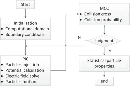
Figure 4.Flow chart of simulation.
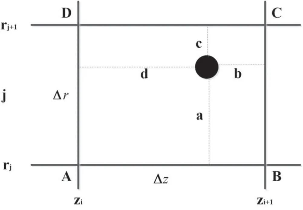
Figure 5.Charge weight method.
Firstly, the whole simulation domain was meshed along the axial and radial directions.Ions are injected into simulation domain from the left boundary and their charges are weighted to the surrounding cell nodes.Secondly, the electric potential is calculated by solving Poisson equation,and the electric field is obtained according to the relationship between the electric potential and field.The electric field is interpolated and the charge particles are accelerated by using the Newton’s second law.Then the production of the CEX ions is simulated,and the newly created CEX ions are directly coupled into the PIC model, whereas the charges of lost ions are deleted.The above process is carried out in a loop.The code is converged when the maximum error of the electric field between iterations of all cell nodes in the calculation reaches less than 0.05%, and then the statistical properties of the particle at steady state are obtained.
2.2.2.PIC model.The amounts of ions that an aperture can extract and focus into a beam current for a given applied voltage is related to the space-charge effects characterized by the Child–Langmuir equation [1]
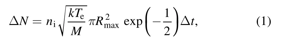
wherenidenotes the ion density at upstream of screen grid;kis the Boltzmann constant;Teindicates the electron temperature;Mis the ion mass;Δtis the timestep and it is 1.15×10⁻¹⁰s in this paper.
The initial position of ions in theZdirection is located in theZ=0 plane, and the radial position is a circular emitting surface that is related withRmaxand random number.The initial position of ions is expressed as
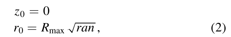
whereranis a random number between 0 and 1.
To ensure the stability of the sheath that caused by the bipolar diffusion of the ions and electrons, the incident velocity of ions entered into the sheath must be in accord with the Bohm polymerization judgment,that is,the initial velocity of ions in theZdirection is determined by Bohm criterion

whereTeis the electron temperature that varies with the radial distance from the center of the thruster.Radial initial velocity of ions satisfies the Maxwell’s velocity distribution.
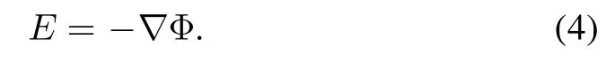
For linear materialsΦ andEcan be related as
The Poisson equation in the cylindrical coordinate system is described as
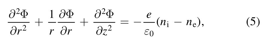
whereε0is the Boltzmann’s constant;eis the quantity of electric charge.neis the electron number density.
To avoid statistical noise, a large number of macro particles are required.The model tracks charged particles as macro particles and takes into account the effects of electric and magnetic fields.In the simulation each macro particle represents a large number of individual charge particles and it is related to the macro particle weight.
The computer macro particle weighting is defined as[17]
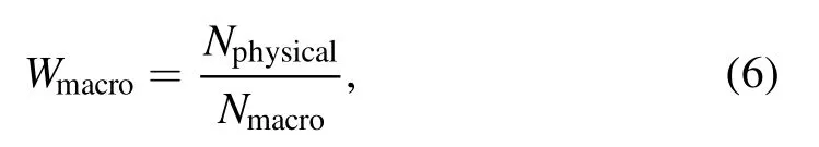
whereNphycialis the total number of physical particles;Nmacrois the total number of macro particles.The particle weighting is assumed to be 1000 in this paper.
Charge of ions is weighted by a method that called charge weight method [18, 19], which is shown in figure 5.
ΔzandΔrare the lengths of the grid in axial and radial positions, respectively.
A charged particle (black point) locates in a grid that is composed of four nodes represented by A, B, C and D.The axial position of four nodes are denoted by (zi,rj), (zi+1,rj),(zi+1,rj+1) and (zi,rj+1), respectively.
The charges of the four nodes are expressed as follows:
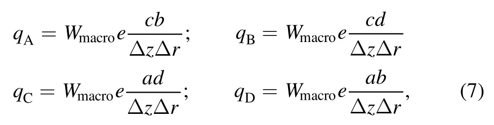
whereaandcare the radial distances from the particle to the nodeiand nodei+1;dandbcorrespond to the axial distances.
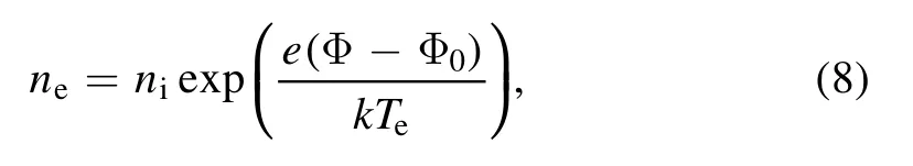
Electron is assumed to be a constant temperature collision-free fluid and its density complies with the Boltzmann distribution.The expression of electron density at upstream of screen grid is presented by equation (8)where Φ0andTeare the electric potential and electron temperature at upstream of the screen grid, respectively.
The electron density at downstream of decel grid is given by
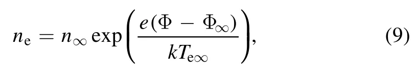
where∞n,Φ∞and∞Teare the plasma density,electric potential and electron temperature at downstream of decel grid,respectively.
Magnetic field is ignored in this model, so that the equation of motion for an ion with a velocityviis described by the Newton’s second law [19]
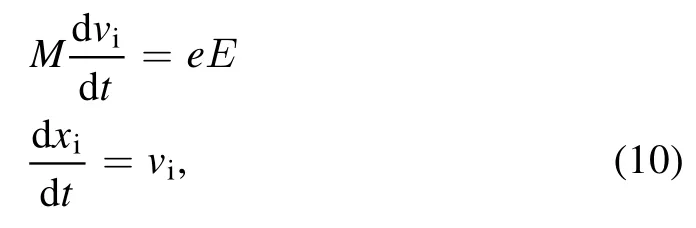
wherexirepresent the position of the ion.
2.2.3.MCC model.Collision between ions and atoms can be shown as

The possibility of occurrence of the collision is dependent on the cross-section, ion density, ion velocity and timestep.

where ( )σ viis the cross-section area;nnis the atom density.A random number is generated by the computer freely.The CEX collision occurs if the random number is smaller than the possibility, and then a newly CEX ions generated.The system time is introduced as the seed of generating the random number to avoid the same number generated.
The collision cross-section for xenon is written as [20]
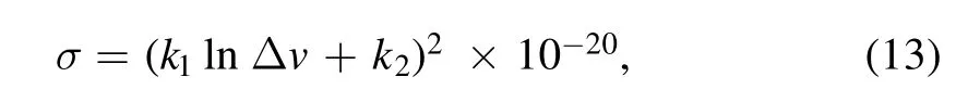
whereΔvis the relative velocity of ions and atoms.The values [18] ofk1andk2are −0.8821 and 15.1262,respectively.
CEX collision directly impacts the performance and the lifetime of the thruster, that is because the collision results in the loss of the beam ions and the production of the relatively cold ions.The most important is that the newly generated and slowly moved CEX ions are attracted by the accel grid with negative voltage and they hit and erode the grid’s barrel and the downstream surface.The materials are sputtered away and the grid structure failure [1, 4, 16] happens if the erosion penetrates through the grid, and the thruster life ends.
3.Results and discussion
3.1.Input condition
Table 1 gives the input parameters of the simulation in this paper.

Table 1.Input parameters.
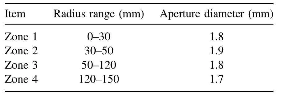
Table 2.Optimization of the optics system by varying aperture diameters.
3.2.Variable aperture design
Ion density and electron temperature downstream of the decel grid are tested by single Faraday probe.The diagnose system shown in figure 6 is composed of the Faraday probe, the power supply and the data acquisition system.The system is mounted on a three-dimensional mobile workbench in a vacuum chamber and is placed 50 mm downstream of the decel grid.ItsZaxis direction is aligned with the central axis of the thruster by adjusting the system’s position.During the test, a computer controlled the mobile workbench is used to make the Faraday probe move along theXdirection and sweep through the beam region, reading 100 number every 2 mm scanning step.
The experiment is performed in TS-7B vacuum equipment that consists of the vacuum chamber, the power processing unit, the xenon flow control unit and the controller system.The propellant is xenon,and the operating vacuum is less than 6×10⁻³Pa.The operating parameters of the thruster are the same as the simulation condition shown in table 1.
Figure 7 shows the experimental results of the radial distribution of the ion density and the electron temperature at the 50 mm distance from the downstream of the decel grid.
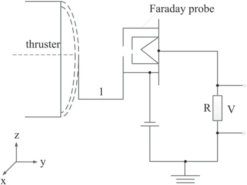
Figure 6.Schematic diagram of the test system.
It is shown that the ion density decays with the radial distance from the center of the thruster closer to an exponential function, but the electron temperature decreases lineally.The variation range of the ion density is from 4.7×10¹⁷to 1.97×10¹⁷m−3, while the electron temperature declines from 5.5 to 1.1 eV.The maximum ion density is about 2.38 times than the value in edge area,so that the beam flatness is about 0.69.
To analyze the influence of the ion density and the electron temperature on the performance and lifetime of thruster, numerical simulations are conducted, where the experimental results shown in figure 7 are treated as the input conditions.Firstly, the maximum beam current that extracted by each aperture is investigated.The beam current is related to the numbers and velocities of ions, and the geometricstructure of grid.
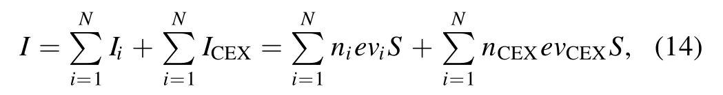
wherenCEXandvCEXare the numbers and velocity of CEX ions, respectively;Sis the cross-section of the grid.
Particles that moved out of the calculation domain from the right boundary will form the beam current of this round aperture.The number of these particles is counted automatically by the code, and corresponding beam current is calculated by using equation (14).Then the beam current generated by each particle is superimposed and the maximum beam current of an aperture is received.Figure 8 shows the simulated maximum beam current of an aperture.
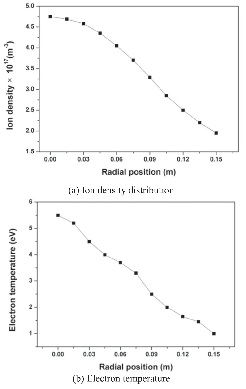
Figure 7.Experimental results of ion density and electron temperature.
The maximum beam current that one aperture extracted is limited by the ion space charge in the gap between the screen and accel grid, which is specified by the Child–Langmuir equation[19].The simulation result shows that the maximum beam current per aperture decreases with the distance from the center of the thruster, and it ranges from 1.5×10⁻⁴to 2.3×10⁻⁵A.Simulation result fits very well with the theoretical analysis shown in equation (14) that the beam current is proportional to the number of ions leaving from the right boundary.The expression of the density current is obtained from figure 8,Taking 24 540 holes into account and integrating the above equation along the radial direction, and the beam current of the thruster is obtained, that is about 2.04 A.The designed value is 2.1 A.
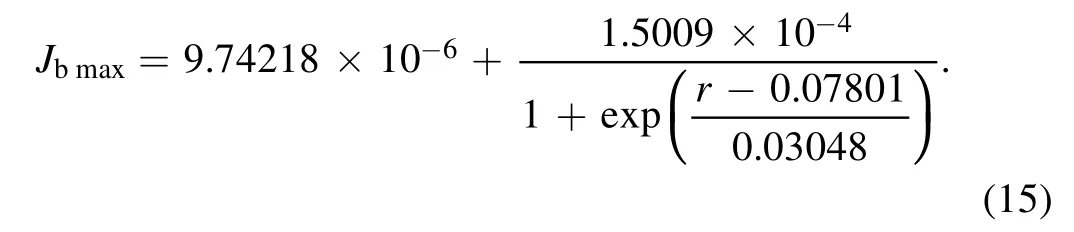
Figure 9 shows the variation of the maximum beam current of one aperture with the ion density for two different electron temperatures.
The simulation results show that the maximum beam current rises with the increase of the ion density and it is larger for high electron temperature than the lower one.The maximum beam current in the center area is about 2.236 times for the 5.5 eV electron temperature than 1.1 eV ones.The variation tendency can be interpreted by the perveance of the ion grids.The perveance is the extracting ability of ion optics for a given applied voltage,which is related to the ion density upstream of the screen grid.The higher the ion density is,the larger the maximum beam current per aperture is.Electron temperature in the ion optics will affect the electric potential and electric field, so it indirectly has an impact on the maximum beam current of an aperture.
Figure 10 shows the variation of the maximum beam current of one aperture with the electron temperature for two different ion densities.
It is also shown that the maximum beam current increases with the increasing of the electron temperature.The maximum beam current in the center area is about 2.47 times for high ion density than the low one,which indicates that the ion density upstream of the screen grid will greatly affect the performance of the thruster.The conclusion shown in figures 9 and 10 are exactly the same that the beam current per aperture is not only determined by ion density, but also the electron temperature,and there is a big difference between the values of the center area and the edge area.
To investigate ion trajectories and the perveance of the beam current, the ion density in the center and the edge area are chosen, that is 4.7×10¹⁷m−3and 1.9×10¹⁷m−3,respectively.The simulation results are shown in figure 11.
The simulation results show that when the ion density is 4.7×10¹⁷m−3, some ions are impinged on the upstream of the accel grid,which is circled in red.It is the result of the too large ion density or too low voltage for the plasma density that pushes the sheath toward the screen aperture and accelerates ions directly into the accel grid.The beam ions are over-perveance in this condition[16].Whereas the beam ions are focused,accelerated and extracted very well when the ion density is 1.9×10¹⁷m−3, no ions are intercepted by the accel grid.It is shown in figure 11 that the focusing point of the low ion density is more concentrated than the high ion density and its divergence angle is smaller than the one in the center area.To make ions extracted very well,we need to find the optimal perveance condition.For a thruster with constant power input, only accel grid voltage can be changed in accordance with the experiment values.So the method is to adjust this parameter based on the relationship between the impingement to beam current ratio and perveance fraction.Figure 12 shows the calculated result of this relationship.
It is shown that the ions are under-perveance when the perveance fraction is less than 0.1, while they are over-perveance when the perveance fraction is larger than 0.8.On the basis of the relationship between perveance fraction and the voltage of the screen grid and accel grid and the geometric parameters[3]of ion optics,and the result shown in figure 12,−220 of the accel grid is chosen.Figure 13 shows the ion density distribution of the −220 V accelerator voltage.
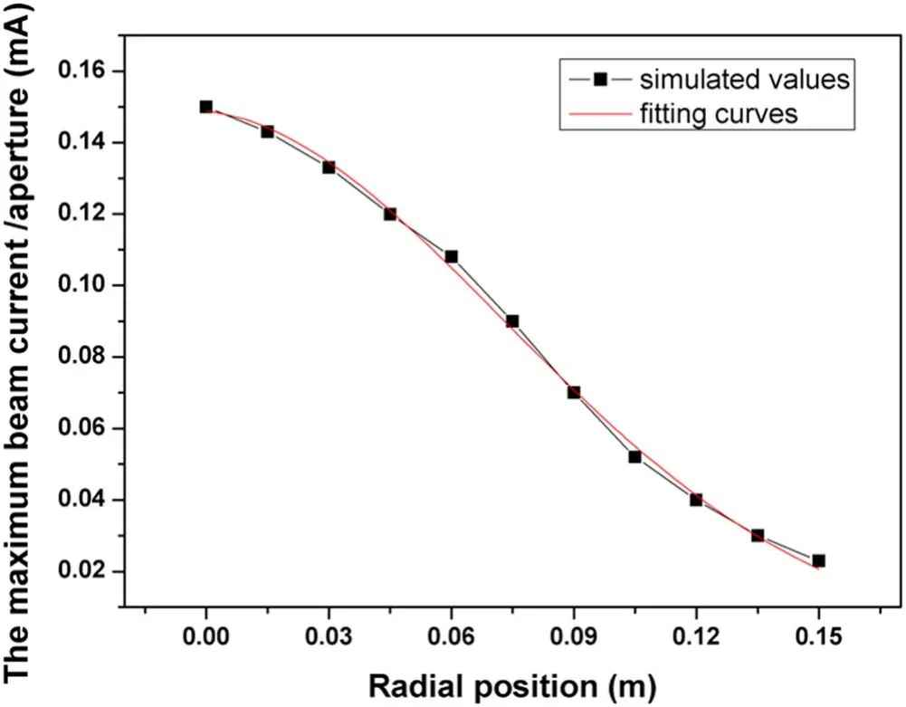
Figure 8.The maximum beam current of one aperture.
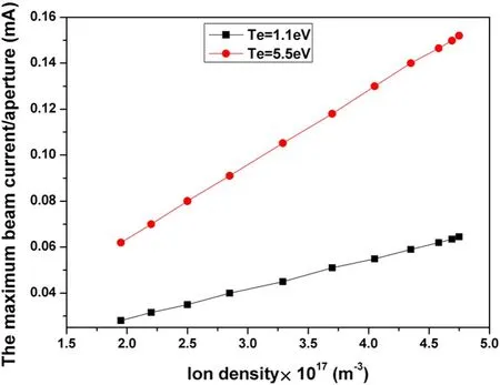
Figure 9.The maximum beam current of one aperture for two electron temperatures.
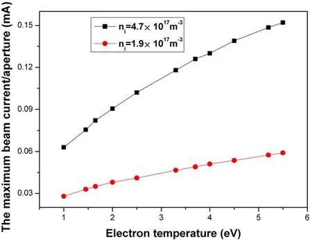
Figure 10.The maximum beam current of one aperture for two ion densities.
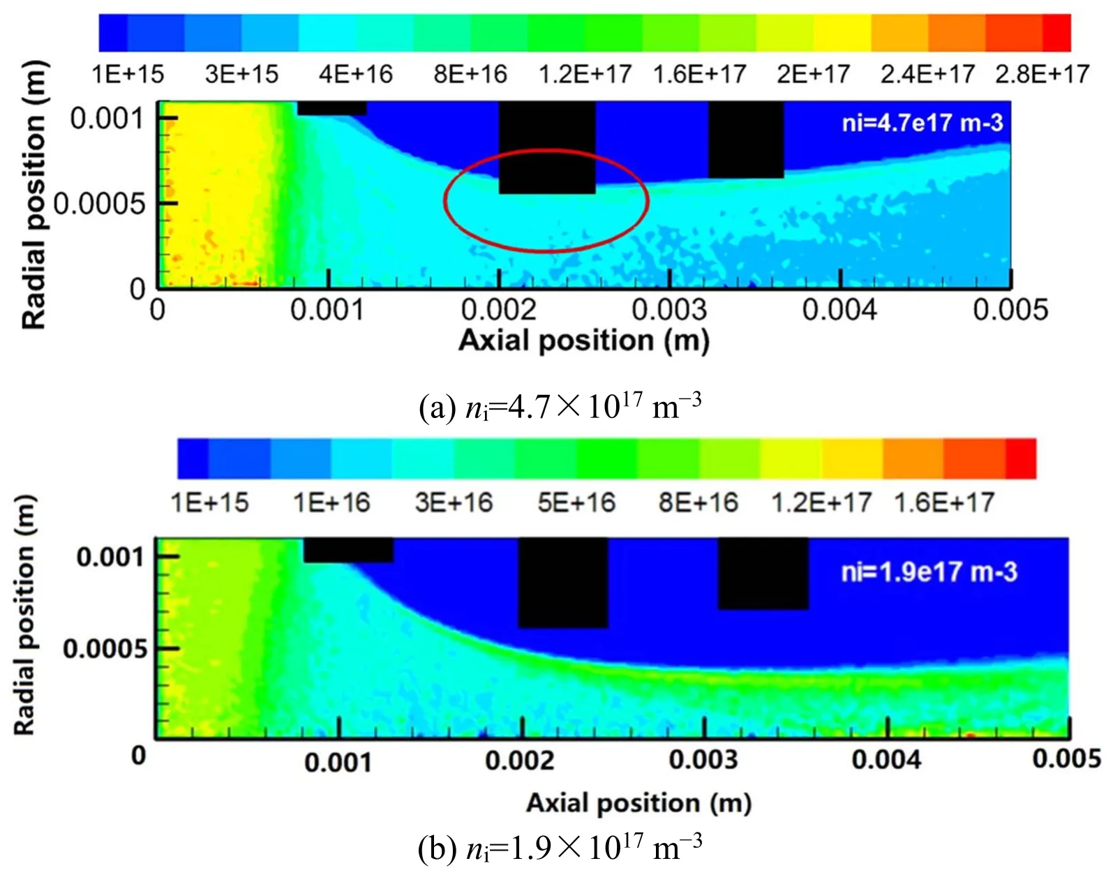
Figure 11.The ion density distributions in the center and edge area.

Figure 12.Impingement to beam current ratio with the perveance fraction.
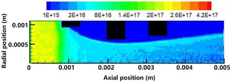
Figure 13.Ion density distribution of −220 V accelerator voltage.
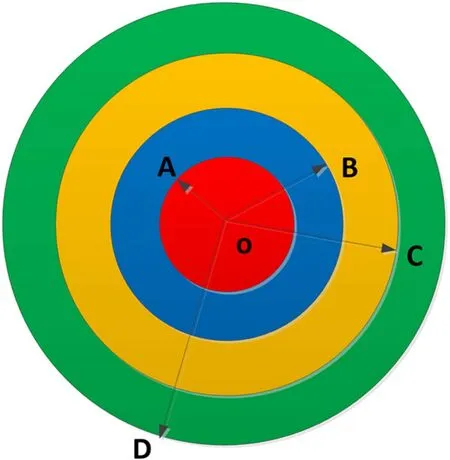
Figure 14.Concept of variable aperture.
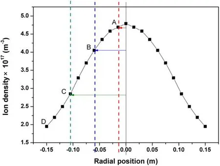
Figure 15.Radial distribution of ion density.
The simulation result shows that there are no ions directly impinged on the accel grid, and all of ions are extracted and focused perfectly.It is shown that the focusing point moves inside to the center of the thruster when the accelerator voltage increased.
Variable aperture ion optics is proposed to decrease the ion density in the center area of the thruster, improve the flatness and promote its reliability and lifetime.Variable aperture is that it artificially reduces the ion density by altering the aperture diameter of the screen grid holes, where the diameters of the accel and decel grids remain constant.The whole screen grid surface will be divided into several zones, and the diameter in each zone is same and its size is determined by the ion density and electron temperature upstream of the screen grid.Ion optics is a convex lens and the distance between grids is only 1 mm.Because of the thermal deformation and very high alignment requirement,the number of zones should be as little as possible.Here four zones are considered,the concept of the variable aperture ion optics is shown in figure 14.
The whole surface of the screen grid is divided into four zones and each zone from the center to the edge region is represented by Zones 1, 2, 3 and 4, respectively.Their radii are denoted byrOA,rOB,rOCandrOD, respectively.The length or the area of each zone is determined by ion density and electron temperature, shown in figure 15.
The ion density and electron temperature in Zone 1 are assumed to ben(1) andT(1), respectively, and the values in other zones are expressed byn(i) andT(i), whereiis the one of the zones left.Depending on the Child–Langmuir equation,the relationship between the values in the center and other areas is obtained,
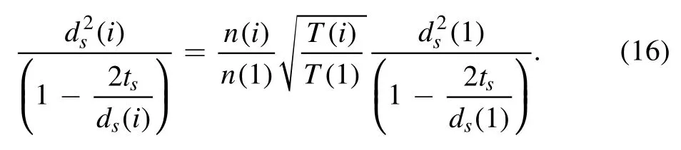
Combined the equation (16) with the experimental results shown in figure 7, the diameter of screen aperture in each zone can be gained, as shown in table 2.
It is shown that the diameters of screen aperture in the whole screen grid surface are all decreased.Aperture in the center area is reduced from 1.95 mm to 1.8 mm, while it is 1.9 mm, 1.8 mm and 1.7 mm in Zones 2, 3 and 4, respectively.The PIC-MCC model is used to simulate the extraction and focusing processes of the ions of the new design.Figure 16 shows the radial distribution of the ion density 50 mm downstream of the decel grid before and after the design of variable aperture.
Black curve represents the radial distribution of the ion density for the original design,while the red one is the results ofthe new ion grids.The most obvious change of the variable aperture is that the ion density in the central region is greatly reduced,but increased in the edge region.It is analyzed that the maximum perveance for round aperture is inversely proportional to the diameter of screen grid, so that the ion density should be increased for the small aperture, but in the center area it is the result of the reduction of the beam current diameter.The simulated results show that the maximum ion density of the variable aperture ion grids is decreased by 10.6% and 6.99% in Zone 1 and Zone 2, respectively, whereas it is increased by 6.49% and 22.3% in Zone 3 and Zone 4, respectively.According to the definition of the beam flatness [1], and the simulation results shown in figure 15,the beam flatness of the variable aperture is calculated and it is improved from 0.69 to 0.88.
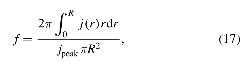
wherefis the beam flatness;Ris the radius of the thruster;ris the radial position of ion;j(r) is the ion density distribution;jpeakis the peak ion density.
To verify the simulated results, the validity and the engineering availability of the variable aperture ion optics,an experimental test is performed in vacuum chamber TS-7B,and the radial ion densities at the 50 mm distance from the downstream of the decel grid are measured.The measuring error of the Faraday probe is about 3.78%.The simulation results at this distance are theoretically inferred from the values of the right boundary where the steady state of the beam current is obtained.The comparison of the experimental and simulation results is shown in figure 17.
The results show that the simulation result of the ion density distribution is in good agreement with the experiment ones,and the maximum error between them is about 5.37%.It is found that the experimental results are higher than the simulation values, which is because the beam current produced by neutral atoms is ignored in simulation model.
The ion density distribution for the new grid is simulated.Figure 18 shows the simulation results for four zones.
It is shown that ions in all cases are all extracted perfectly and there are no ions intercepted by accel grid directly,which indicates that the perveance of beam current for new grid will not be affected by variable aperture.The simulation results verify the reasonability and effectiveness of the diameter design of the variable aperture.
Figure 19 shows the maximum beam current extracted by an aperture for the new grid is calculated using the simulation model.
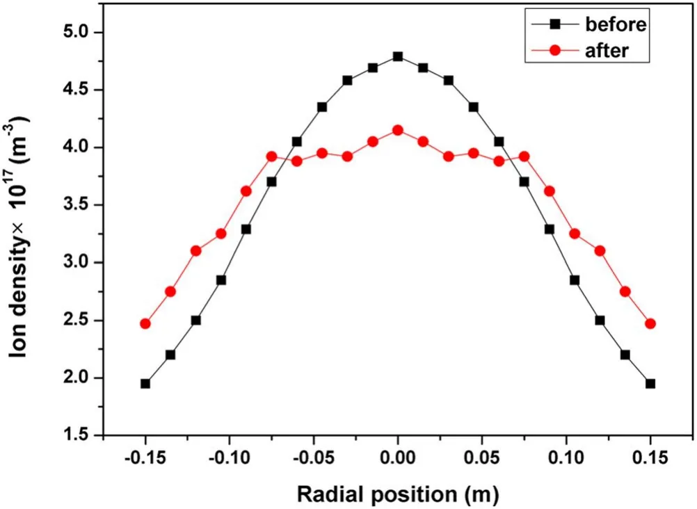
Figure 16.Ion density radial distribution.
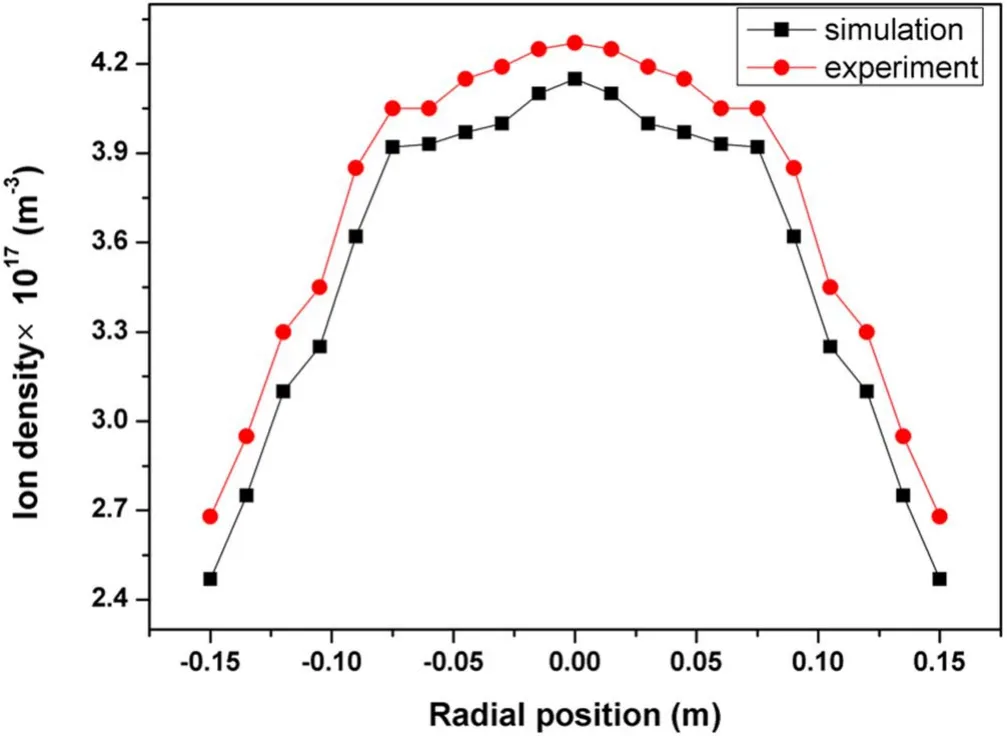
Figure 17.Comparison of the simulation and experimental ion density.
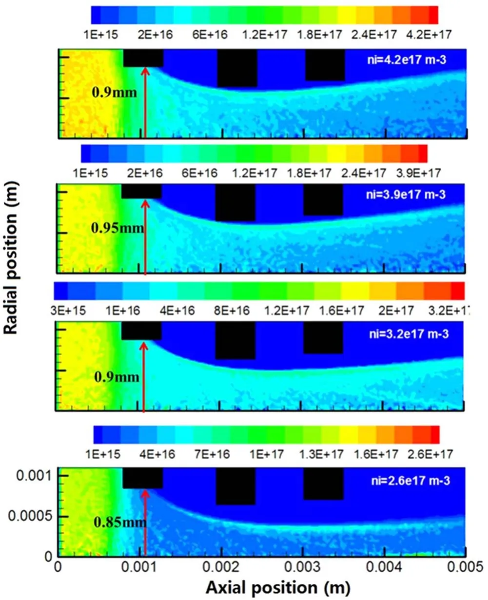
Figure 18.Ion density distributions for four zones.
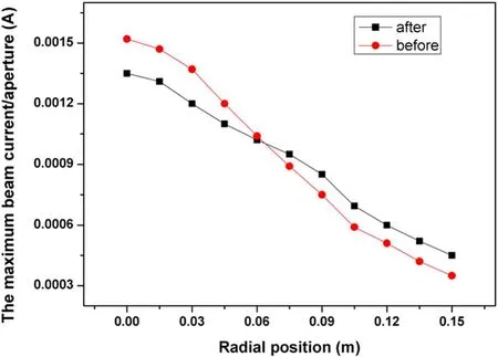
Figure 19.The maximum beam current for the new grid.
The results show that the variable tendency for the new grid is the same as the old one.However,the maximum beam current that one aperture can extract is increased in the Zones 1 and 2,but it is opposite for Zones 3 and 4.The equation of the fitting curves of the old and new ion optics are given as follows
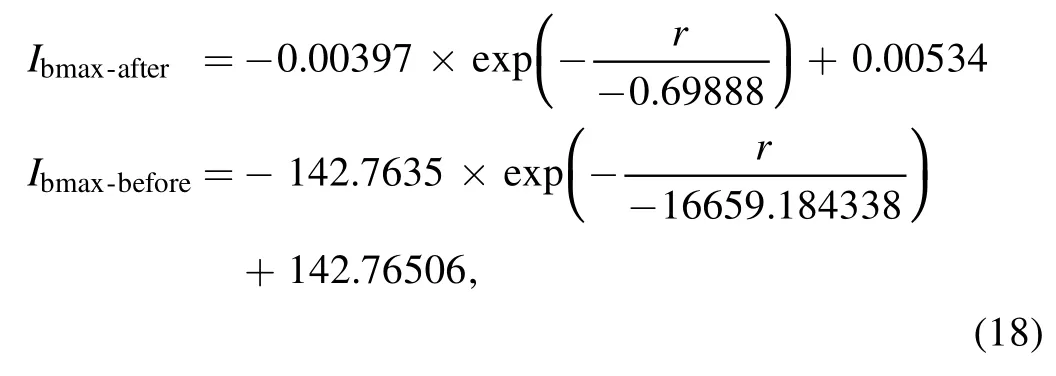
whereIbmaxis the maximum beam current;ris the radial position of ion.
Integrating the above equation along the radial direction,the total beam currents for the two cases are obtained which are 2.08 A and 1.93 A, respectively.It is found that the total beam current of the new grid is decreased by 7.15%.The erosion rate[16]of molybdenum material is related to the number,velocities of ions that hit on the accel grid,and it is calculated according to its definition that the erosion rate of the new grid is about 3.65×10⁻¹⁴atom s−1that is much less than the 5.36×10⁻¹⁴atom s−1for the old design, the descent ratio is about 31.9%.
4.Conclusions
Variable aperture is a new concept of the ion thruster ion optics.It is to artificially decrease the beam current density in the center area of the thruster by using different aperture diameter of the screen grid.The screen grid surface is divided into several zones and the aperture diameter in each zone is determined by the ion density and the electron temperature upstream of the screen grid.The simulation results in this paper show that the variable aperture can greatly increase the beam flatness from 0.69 to 0.88 and reduce the erosion rate about 31.9%, but it makes the maximum ion density in the center area of grid decreased by 10.6%, and leads to the 7.15% decrease of the total beam current, this is the result of the reduce of the aperture diameter of the screen grid.
Acknowledgments
This work is supported by Top Young Talents of China Aerospace Science and Technology Corporation, Innovation Group Project of Gansu Province and National Natural Science Foundation of China (No.11802111).
 Plasma Science and Technology2021年10期
- Plasma Science and Technology的其它文章
- Numerical study of the grid erosion of field emission electric propulsion
- Experimental study of a porous electrospray thruster with different number of emitterstrips
- Design and fabrication of a full elastic submicron-Newton scale thrust measurement system for plasma micro thrusters
- A plasma equilibrium model for rapid estimation of SF-MPDT performance
- Numerical simulation of the effects of protrusion on DC arc anode attachment
- The ablation characteristics of laser-assisted pulsed plasma thruster with metal propellant