
The ablation characteristics of laser-assisted pulsed plasma thruster with metal propellant
2021-10-31 08:14YuanzhengZHAO赵元政ShengTAN谭胜JianjunWU吴建军YuZHANG张宇YangOU欧阳andPengZHENG郑鹏
Plasma Science and Technology 2021年10期
Yuanzheng ZHAO (赵元政), Sheng TAN (谭胜), Jianjun WU (吴建军),Yu ZHANG (张宇), Yang OU (欧阳) and Peng ZHENG (郑鹏)
College of Aerospace Science and Engineering, National University of Defense Technology, Changsha 410073, People’s Republic of China
Abstract In this study, a laser-assisted pulsed plasma thruster (LA-PPT) with a novel configuration is proposed as an electric propulsion thruster which separates laser ablation and electromagnetic acceleration.Owing to the unique structure of the thruster, metals can also be used as propellants, and a higher specific impulse is expected.The ablation quality, morphology, and plume distribution of various metals (aluminium alloy, red copper, and carbon steel) with different laser energies were studied experimentally.The ablation morphology and plume distribution of red copper were more uniform, as compared to those of other metals, and the ablation quality was higher, indicating its greater suitability for LA-PPT.The plume generated by nanosecond laser ablation of aluminium alloy expanded faster, which indicated that the response time of the thruster with aluminium alloy as the propellant was shorter.In addition,when the background pressure was 0.005 Pa, an obvious plume splitting phenomenon was observed in the ablation plume of the pulsed laser irradiating aluminium alloy, which may significantly reduce the utilisation rate of the propellant.
Keywords: plasma plume expansion dynamics, plume splitting phenomenon, nanosecond laser ablation, laser-assisted pulsed plasma thruster
1.Introduction
Owing to the high specific impulse and accurate thrust of electric propulsion thrusters, an increasing number of satellites are equipped with electric propulsion thrusters as propulsion systems[1,2].As a type of electric propulsion,pulsed plasma thrusters (PPTs) play a pivotal role in micro/nano satellite propulsion systems owing to their simple structure,low cost, high reliability, and easy miniaturisation [3–6].However, PPTs still have the disadvantage of ‘late-time ablation’, in which the propellant surface proceeds to be ablated after the thruster completes the entire working period.Because of late-time ablation,some particles on the propellant surface are not accelerated by the thruster, resulting in low propellant utilisation efficiency and low thruster efficiency[7–9].In addition, PPTs have the difficulties of carbon deposition in spark plugs and plume pollution.To enhance the propulsion performance of PPTs, Kawakamiet alpresented a laser-assisted PPT (LA-PPT), which uses laser irradiation instead of spark plug ignition to generate plasma[10–12].However, when the propellant comes within close range of the discharge channel, the laser-assisted PPT still undergoes late-time ablation.To reduce the late-time ablation further and optimise the thrust performance, Zhanget alproposed a novel LA-PPT[12]and the schematic of the novel LA-PPT is shown in figure 1.Compared to the LA-PPT proposed by Kawakamiet al, the most significant difference of the novel LA-PPT proposed by Zhanget alwas a ceramic tube separating the propellant from the electrical channel.Therefore, during the discharge process, the propellant could not be ablated by the discharge arc between the anode and the cathode, which could effectively solve the late-time ablation problem.In addition, due to the limitations of the traditional PPT and LA-PPT structure, the propellant is exposed in the discharge channel.Only a material with good insulation can be used as a propellant.The ceramic tube is used in the novel LA-PPT to separate the propellant from the discharge channel,so that all kinds of materials including metals can be used as the propellant [13].
Polymers have poor thermal conductivity and high ionisation energy, while metals have good thermal conductivity and low ionisation energy.Compared with polymers,the ionisation rate of laser ablating metals is higher,and plasma is easier to form during the ablation process, so the metal propellant has a higher specific impulse and the laser energy utilisation efficiency is higher.
Therefore, it is necessary to study the use of metal materials as the LA-PPT propellant.So far,there are few studies on using metal materials as the propellant of an LA-PPT.The novel LA-PPT uses a ceramic tube to separate the propellant from the discharge channel, so that the LA-PPT can use any aggregate including metal as the propellant like laser propulsion.We conducted literature research on laser ablation propulsion.Currently, metals and polymers are the most frequently used propellants in laser ablation propulsion.Previous studies have noted that using metals as propellants can achieve higher specific impulses than using polymers[14,15].Pakhomovet alused a sub-nanosecond laser to experiment and analyse the propulsion performance of common metals.The result obtained is shown in figure 2 (Xrepresents the energy conversion efficiency in the figure).It can be seen from the figure that in laser propulsion the propulsion performance of medium atomic mass metals (such as Al, Fe, Cu and Zn) is better, which can obtain a higher specific impulse (∼3000 s)and appropriate coupling coefficient (∼15 N MW−1) and energy conversion efficiency (∼0.15) [16].
Zhenget alstudied the ablative laser propulsion of nanosecond laser irradiation by looking at its specific impulse and momentum transfer on copper, lead, aluminium, and graphite targets and found that the material momentum was affected by the ambient pressure and material properties[17].Mahmoodet alstudied pulsed-laser-ablated iron and aluminium plasma plumes in the background argon gas and found that the splitting of iron plasma plumes occurred at 0.5 and 1.0 mbar and that of aluminium plasma plumes occurred at 0.2 mbar [18].Chenget alablated aluminium targets and found that a change in the laser fluence had an effect on the fluctuation of the impulse coupling coefficient, and the deterioration of the coefficient at high fluence was caused by the plasma shielding effect [19].Mohamedet alstudied the effects of an appropriate combination of laser wavelengths and pulse energies on the generated copper plasma characteristics and measured the electron temperature and electron density for various laser wavelengths and pulse fluences[20].
Besides, compared with polymers, metals have high laser absorption coefficient and thermal conductivity, and lower ionisation energy [21], so the metal propellant has a higher utilisation rate of laser energy, and the metal has a higher ionisation rate in laser ablation.Plasma is easier to form during the ablation process, leading to larger consumed mass.In this study,based on the previous research conclusions,three metals were selected: aluminium alloy, red copper, and carbon steel,to study the laser ablation characteristics.This paper experimentally studied the ablation quality, morphology and plume distribution of different metals (aluminium alloy, red copper and carbon steel)under different laser energies.It has reference significance for propellant selection and structure optimisation of the novel LA-PPT.The working process of our novel LAPPT consists of two steps.First, the focused-laser-beam-ablated propellant generates a plasma plume or vapour jet which expands and enters the discharge channel between the electrodes.The plasma plume is then accelerated by the discharge channel, producing thrust.The expansion of laser-induced plasma in the first part significantly affects the electromagnetic acceleration in the second part.Hence,it is necessary to clarify the mechanism of LA-PPT in the investigation of plasma plume expansion dynamics; however, to date, there has been little discussion on this topic.
Therefore, in this study, we address this literature gap and investigate the laser-induced plasma plume expansion dynamics of aluminium alloy, red copper, and carbon steel.
2.Experiment
A diagram of the laser ablation experimental setup is shown in figure 3.In our experiment, the laser beam was generated by a Nd:YAG laser with a maximum energy of approximately 900 mJ(pulse duration of ∼8 ns full width at half maximum,laser wavelength 1064 nm).The focal length of the lens,focusing the laser beam on the propellant (or target), was 400 mm.Both the target and the lens were in a vacuum chamber.An ultra-high-speed intensified charge-coupled device (ICCD) (Model: XXRapidFrame) manufactured by Stanford Computer Optics, Germany, was placed parallel to the target to acquire two-dimensional images of the plasma plume.4Spec software originally supplied with the ultra-highspeed ICCD was used to analyse pictures.A digital delay pulse generator generated three TTL pulse signals, which triggered the Nd:YAG laser and the ultra-high-speed ICCD separately.Two signals with a time interval of 220 μs triggered the light switch and Q switch of the laser, and another signal triggered the ultra-high-speed ICCD.
To compare the plasma motion generated by different targets and improve our understanding of the plasma plume propagation, we set the ICCD exposure time to 10 ns as a constant during the entire experiment.
3.Results and discussion
3.1.Mass shot and morphology of ablated metals
In our experiment,the propellant was ablated at a pressure of 0.005 Pa.As the consumed mass of metals per ablation was too small to measure directly, we used an electronic microbalance (Model: XS205DU, Mettler Toledo, Switzerland) to measure the consumed mass after ablating 500 times and taking the average consumed mass as the mass bit per shot.During the LA-PPT operation, moving the target after each ablation would complicate the system and limit the working frequency of the thruster.Therefore, the ablation uniformity of the propellant was evaluated by observing the ablation morphology to select the propellant that could be ablated multiple times on the same ablation surface.The morphology of the propellant after 500 ablation cycles was observed using an electron microscope.
The materials of the propellant come from commercially available materials, and the composition and basic properties are shown in table 1.
Figure 4 presents the ablation mass data for the metals.As can be found, with an increase in the laser energy, the single-pulse ablation mass of the three metals increases.However, the increment decreases gradually.The reason for this tendency of single-pulse ablation mass may be that as the laser energy is increased, the earlier the plasma is generated,and the stronger the plasma shielding of the laser radiation.Therefore, the laser energy reaching the metal surface is reduced more.Among the three metals,the maximum singlepulse ablation mass is only 1.172 μg, which means that thepropellant supplied to the thruster using the laser ablation metal will be insignificant, especially at low laser energy.
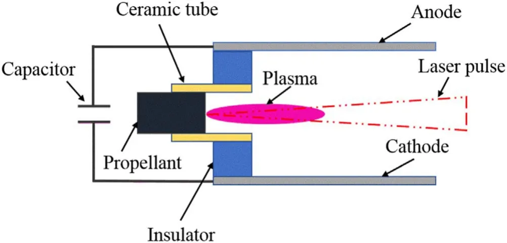
Figure 1.Schematic of the novel LA-PPT.
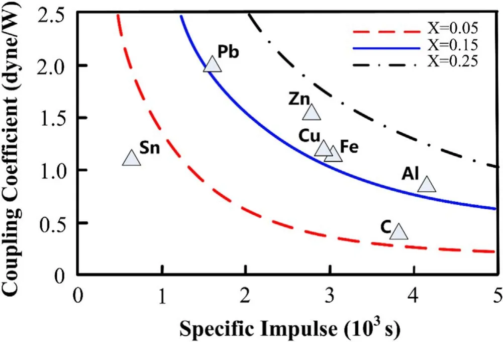
Figure 2.Propulsion performance of some simple substance propellants in laser ablation propulsion [16].
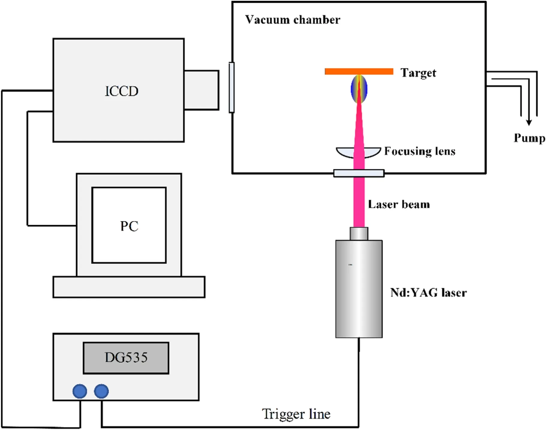
Figure 3.Schematic of the laser ablation system.
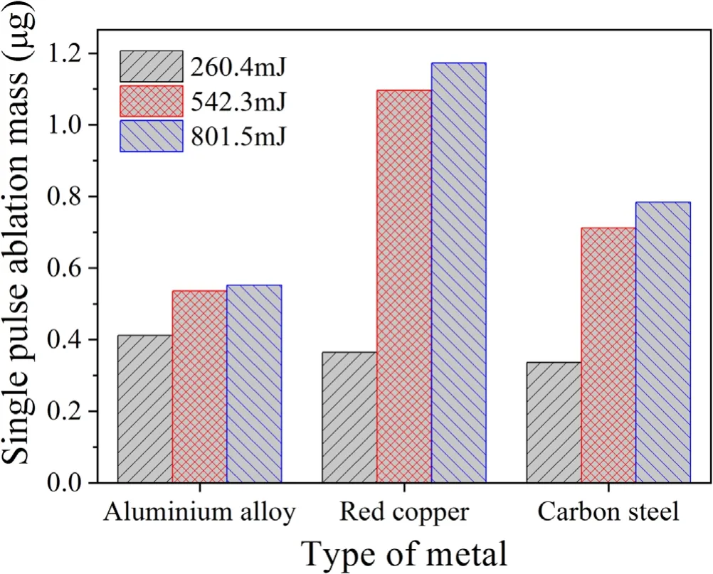
Figure 4.Single-pulse ablation quality of metals.
When the laser energy is low,such as 260.4 mJ,after the metal is melted and vaporised, the ionised part is less.In our opinion,the ablation quality of metal is mainly affected by the melting point of metal materials at low laser energy.The melting point of aluminium alloy is low, so the ablation quality of aluminium alloy is larger under low laser energy.When the laser energy is large,the ionisation rate is high after the metal is melted and gasified.The quality of metal ablation is mainly affected by metal density and thermal conductivity.The densities of copper and carbon steel are larger than that of aluminium alloy.Therefore, the ablation quality of copper and carbon steel is relatively large.In addition, since the thermal conductivity of copper is larger than that of carbon steel and aluminium alloy, when the laser energy increases,the ablation quality of copper is greater.
Figure 5 shows the ablation morphologies of the three metals.From the figure it can be seen that after 500 ablation cycles, the ablation depth of the three metals is relatively shallow, which corresponds to their low ablation mass.After the metals are ablated, in an area more extensive than the ablation circle, evident traces caused by laser ablation can be observed (hereafter, the ablation-affected area).With an increase in the laser energy, the extent of the ablation-affected area of various metals increased, and the traces became increasingly apparent.As these traces are outside the laser ablation circle, the reason may be that the laser ablation of metals produces high-temperature and high-pressure plasma.The plasma radiates,impacts,and diffuses along the surface of the metals.The higher the laser energy, the greater the influence of plasma radiation.The carbon steel generated a more diffuse ablation morphology over the aluminium alloy and copper.We think it is mainly affected by the thermal conductivity and density of the material.Among the three metals,carbon steel has the smallest thermal conductivity.Laser ablation produces high-temperature and high-pressure plasma,which radiates temperature on the surface of the working fluid and impacts the surface of the propellant.Due to the low thermal conductivity of carbon steel, the heat radiated by the plasma diffuses along the surface of the propellant.The aluminium alloy and red copper transfer radiant heat to the inside of the metal.In addition,the density of carbon steel is greater,and the weight of the deposited material is greater.Therefore,the carbon steel generated a more diffuse ablation morphology.
Regarding the uniformity of the propellant, among the three metals, the ablation surface of red copper is the smoothest.I think the thermal conductivity also affects the uniformity of metal ablation.Due to the good thermal conductivity of red copper, the heat distribution of the working medium is more uniform,there is no local heat concentration,and the ablation ring is less.
Multiple ablation rings were observed in the ablation circles of the aluminium alloy and carbon steel samples.In other words, during laser ablation, concentric cracks were generated at the ablation surface, which could affect the uniformity of the subsequent ablation.
3.2.Plasma plume expansion dynamics of laser-ablated metals
3.2.1.Expansion characteristics of aluminium alloy plasma plume.Figure 6 shows the laser ablation plasma plume evolution process of aluminium alloy in gas background at 5×10⁻³Pa.The input laser pulse energy is 542.3 mJ.The plasma plume distribution is symmetrical relative to the axis line of the propellant.Compared with the initial pressure of the plasma,the ambient pressure is lower,thus the plasma plume is almost free from viscous forces and expands freely.In contrast,because the plasma emission intensity corresponds to the plasma temperature and the plasma plume expands adiabatically after the laser pulse termination [22], the plasma temperature decreases over time.Moreover, during the swift expansion of the plasma, the electron number density rapidly decreases, and the probability of electron collision ionisation decreases accordingly.These two factors result in the plume light intensity gradually decreases with time and causes the downwardly expanding plume to experience a process from highlighting to fading.From figure 6, we observe that the brightness of the plasma plume decreases rapidly with time and is extremely low at 1 μs.The results indicate that the time scale of the visible plasma plume is approximately 1 μs.
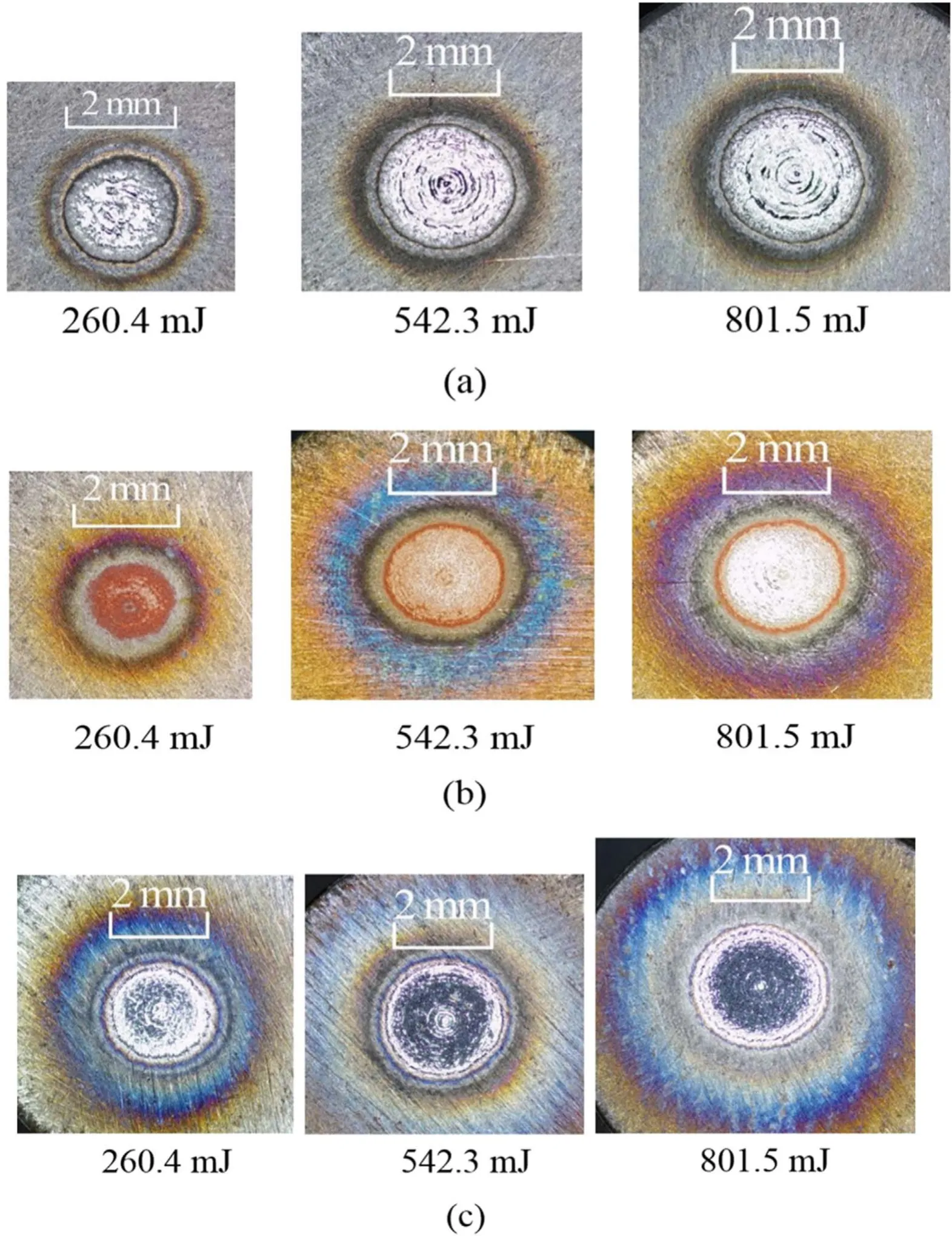
Figure 5.Ablation morphology of the three metals.(a) Aluminium alloy, (b) red copper, (c) carbon steel.
Figure 7 shows the temporal expanding progress of the aluminium alloy plasma plume under different laser energy conditions.A key point here is that the plasma plume occupies a small area as the input laser pulse energy is 260.4 mJ.Therefore,the picture needs to be cropped,and the actual size of the plume should be calculated using the scale length in the picture.
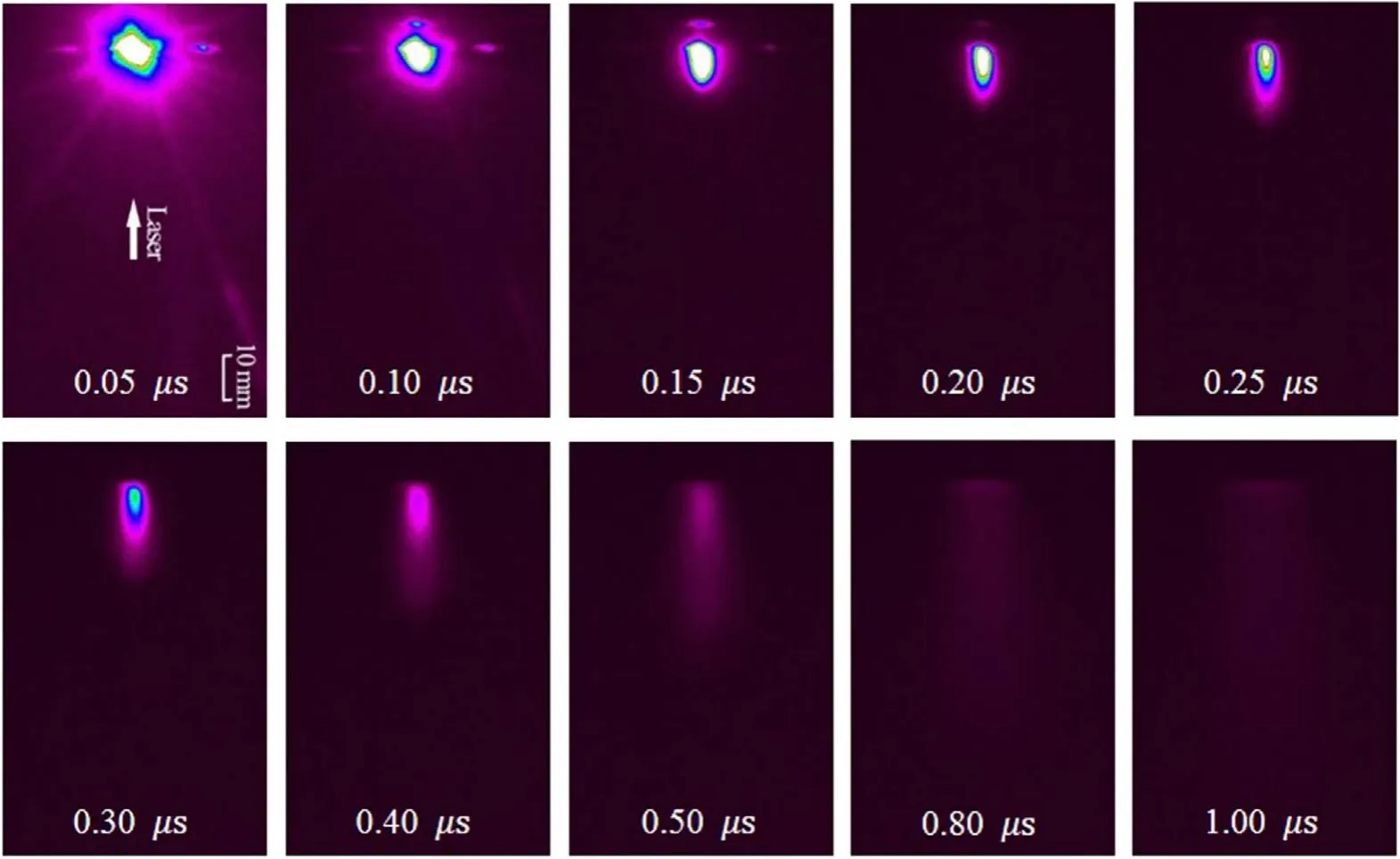
Figure 6.Plasma plume evolution of aluminium alloy in gas background at 5×10⁻³ Pa.The input laser pulse energy is 542.3 mJ.
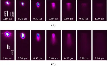
Figure 7.Plasma plume evolution of aluminium alloy at different laser energies in gas background at 5×10⁻³ Pa.(a) 260.4 mJ,(b) 801.5 mJ.
Comparing figures 6 and 7, the overall development process of the plasma plume is similar at different laser energies.They all have a process of rapid expansion and gradual disappearance from high-intensity light.With the increase of laser pulse energy,the plasma is brighter,and its scale increases.Two reasons may explain this phenomenon.First, the higher the laser energy, the higher the ablation mass flow rate, which raises the number density of particles in the excited state.Second,the greater the laser energy,the more incident laser light the plasma shields, causing the plasma to gain more energy from the input laser pulse.This in turn increases the ionisation rate of the plasma and ultimately increases the number density of excited-state particles [23].
The plasma plume intensity gradually decreased and disappeared after 0.5 μs, making it difficult to measure the position of the plume leading edge after 0.5 μs.However,it is not easy to locate the luminous plume expansion front within 0.2 μs because of the excessive light intensity of plasma.Hence, we calculated the front edge velocity of the plasma plumes through the plume front positions within 0.2–0.5 μs.Figure 8 shows that the relationship between the leading-edge length of the aluminium alloy plasma plume and time under various laser pulse energies.As shown in the figure, the leading-edge length of the plasma plume is proportional to the time under different input laser pulse energies.In figure 8,the solid line is obtained by fitting with the formula =L at, and the corresponding fitting equation is listed next to the solid line.It is apparent that the slope of the linear fit becomes steeper with an increase in the laser energy.In other words,the front edge velocity of the plasma plumes rises with the increase of the laser pulse energy.When the laser pulse energy increases, less time is required for the propellant to become plasma,and the plume expansion starts earlier,which explains this phenomenon.Hence,more energy is absorbed in the interaction of plasma with the laser pulses, thus the plasma is faster.

Figure 8.Relationship between the leading-edge length of the aluminium alloy plasma plume and time (background pressure: 0.005 Pa).
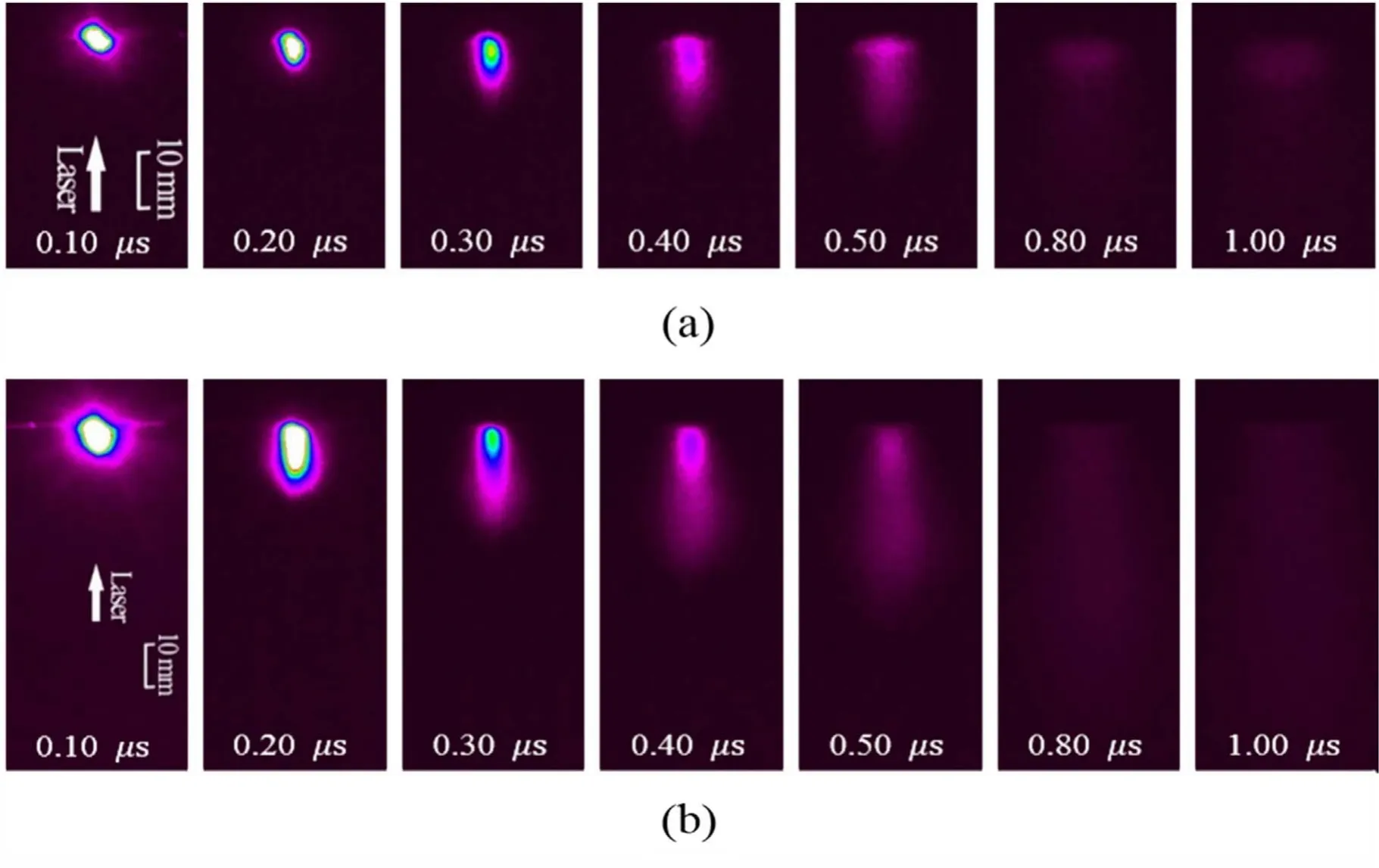
Figure 9.Plasma plume evolution of red copper at different laser energies in gas background at 5×10⁻³ Pa.(a) 260.4 mJ, (b) 542.3 mJ,(c) 801.5 mJ.
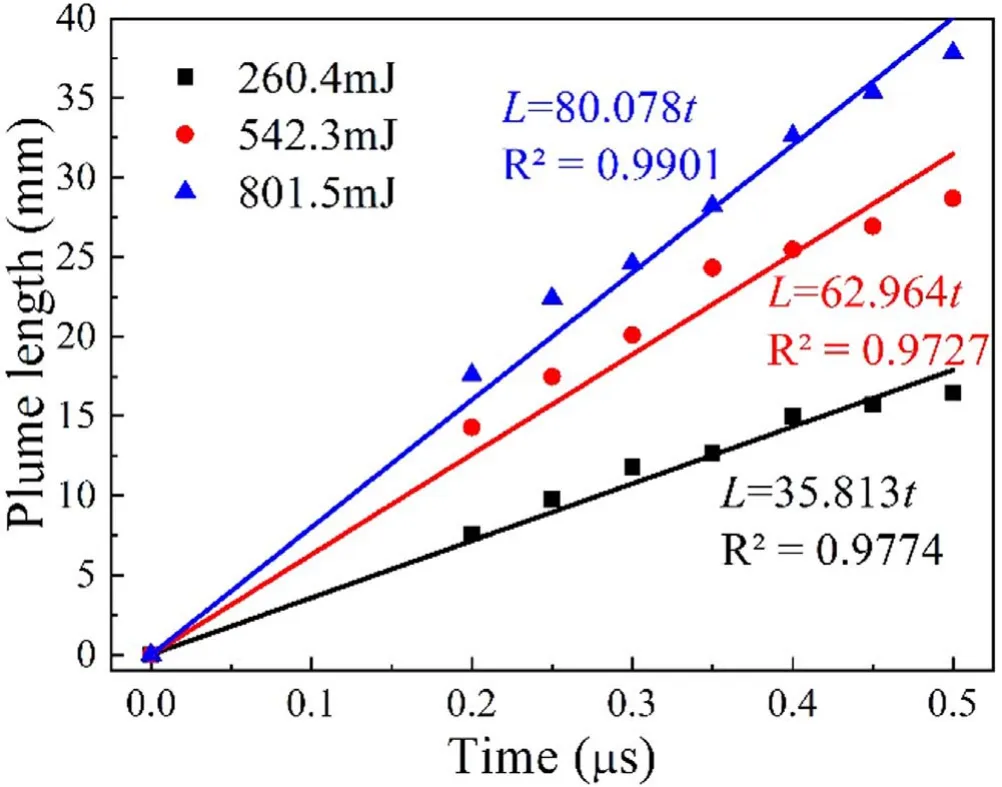
Figure 10.Plasma plume evolution of carbon steel at different laser energies in gas background at 5×10⁻³ Pa.(a)260.4 mJ,(b)542.3 mJ,(c) 801.5 mJ.
3.2.2.Plasma plume expansion characteristics for different metals.The time-resolved images of the red copper plasma plume at varying laser energies are shown in figure 9.For the red copper plasma plume, the plasma brightness, size, and duration at a laser energy of 260.4 mJ are far from those of the other two types of laser energy.It is apparent in figure 4 that the single-pulse ablation mass at a laser energy of 260.4 mJ is also different from those at the other two laser energies.This indicates that copper is more difficult to be ablated by lowerenergy laser light.Comparing figures 6, 7, and 9, we know that the morphology and evolution of red copper plasma plume resemble those of the aluminium alloy plasma plume.
Furthermore, the lifetime scale of the red copper plasma plume is consistent with that of the aluminium alloy plasma plume.In addition, the red copper plasma plume intensity is lower than that of the aluminium alloy plasma plume at the same energy level when the input laser pulse energy is 260.4 mJ.However, the amount of light emitted by the red copper plasma plume at the other two laser energies is higher than that of the aluminium alloy plasma plume at the same energy level.This phenomenon occurs because the melting and boiling points of copper in red copper are higher than those of aluminium in aluminium alloys.
Moreover,as shown in table 2,the first ionisation energy of copper is also higher than that of aluminium; therefore,aluminium is more easily ablated and ionised.However,once ablated substantially, copper will absorb most of the energy before leaving the propellant surface because it needs to be ablated when the surface temperature is higher.Thus, it will have more energy than aluminium at this time, and the light intensity of the red copper plasma plume will be higher.
Figure 10 demonstrates the plasma plume evolution of carbon steel at different laser energies.Among the three metal plumes, the plasma plume of carbon steel has the strongest light intensity because the melting point of carbon steel is the highest among the three metals,and the first ionisation energy of iron in carbon steel is also the largest.When iron is ablated by a large amount,it will absorb a large amount of energy on the metal surface, and the light intensity will be stronger.Comparing the plasma plume at 0.5 μs between the three metals under different energies, we observe that the plasma plume intensity is the highest for carbon steel; this indicatesthat the plasma plume lifetime of carbon steel(approximately 1.8 μs) is longer than that of the other two metals(approximately 1.0 μs).
This phenomenon may be due to a certain proportion of carbon in carbon steel,which improves the absorption rate of the laser energy by carbon steel and enables the deposition of more laser energy.Hence, the plasma plume of carbon steel has the highest intensity and the longest lifetime.Meanwhile,as the lateral displacement of the carbon steel plasma plume is larger than that of the other two metals,the expanded plasma plume front of carbon steel is sharper.Combined with the ablation morphology shown in figure 5, it can be observed that the ablation-affected area on the carbon steel surface due to the plasma radiation and impact is also more extensive than that on the other two metals.This observation is closely related to the more significant lateral displacement of the carbon steel plume.
The plasma plume front positions of red copper and carbon steel from 0.2 to 0.5 μs were determined, and the formula =L atwas used to fit the expansion velocity of the plasma plume front.The velocity of the plasma plume leading edge for different metals is shown in figure 11,wherein it can be seen that the plume velocity of the three metals increases.Amongst the three metals, the velocity of the plasma plume front of aluminium alloy was the fastest, followed by carbon steel and red copper.The main reason for the velocity difference may be that the relative atomic masses of aluminium, copper, and iron, which are the main elements of the three metals under study,are different,with aluminium being the lowest, and copper the highest.This difference in relative atomic mass leads to faster acceleration of the aluminium alloy plasma, whereas copper plasma is the most difficult to accelerate.
3.2.3.Influence of the background pressure on the expansion characteristics of the plasma plume.Figure 12 displays the plasma plume evolution of the different metals in gas background at 5 Pa and an input laser pulse energy of 542.3 mJ.The aluminium alloy plasma plume exhibits different plume structures at the initial stage, and plume images at the early stage are mainly displayed.Comparing figures 6, 9(b), 10(b), and 12, when the plume begins to expand initially, the plume shape and evolution are comparable at different background pressures.The reason is that, compared with ambient pressure, the internal plasma pressure is significantly higher and the plume evolution is negligibly affected by the background pressure.Next, as the plumes evolve further, the aluminium alloy plasma plume presents a different plume structure under the two different background pressures,whereas the plume development of the copper and carbon steel plasma under the two different background pressures is still relatively similar.Concurrently,the plasma light intensity at a background pressure of 5 Pa is slightly higher than that at a background pressure of 0.005 Pa.This may be due to the partial ionisation of the background gas when the background pressure is 5 Pa.
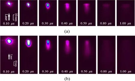
Figure 11.Velocity of the plasma plume front of different metals (background pressure: 5×10⁻³ Pa).
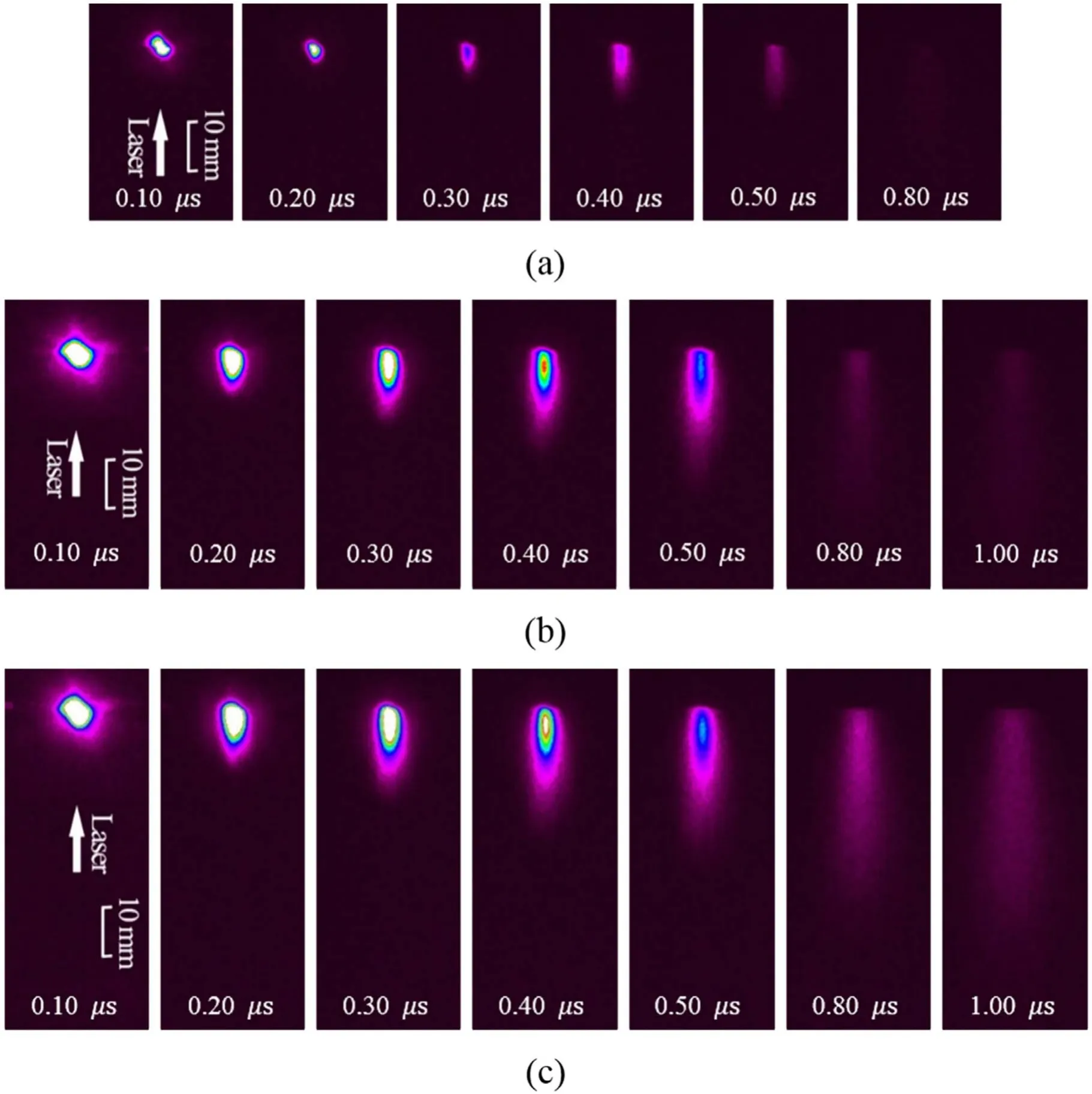
Figure 12.Plasma plume evolution of different metals in gas background at 5 Pa.The input laser pulse energy is 542.3 mJ.(a) Aluminium alloy, (b) red copper, (c) carbon steel.
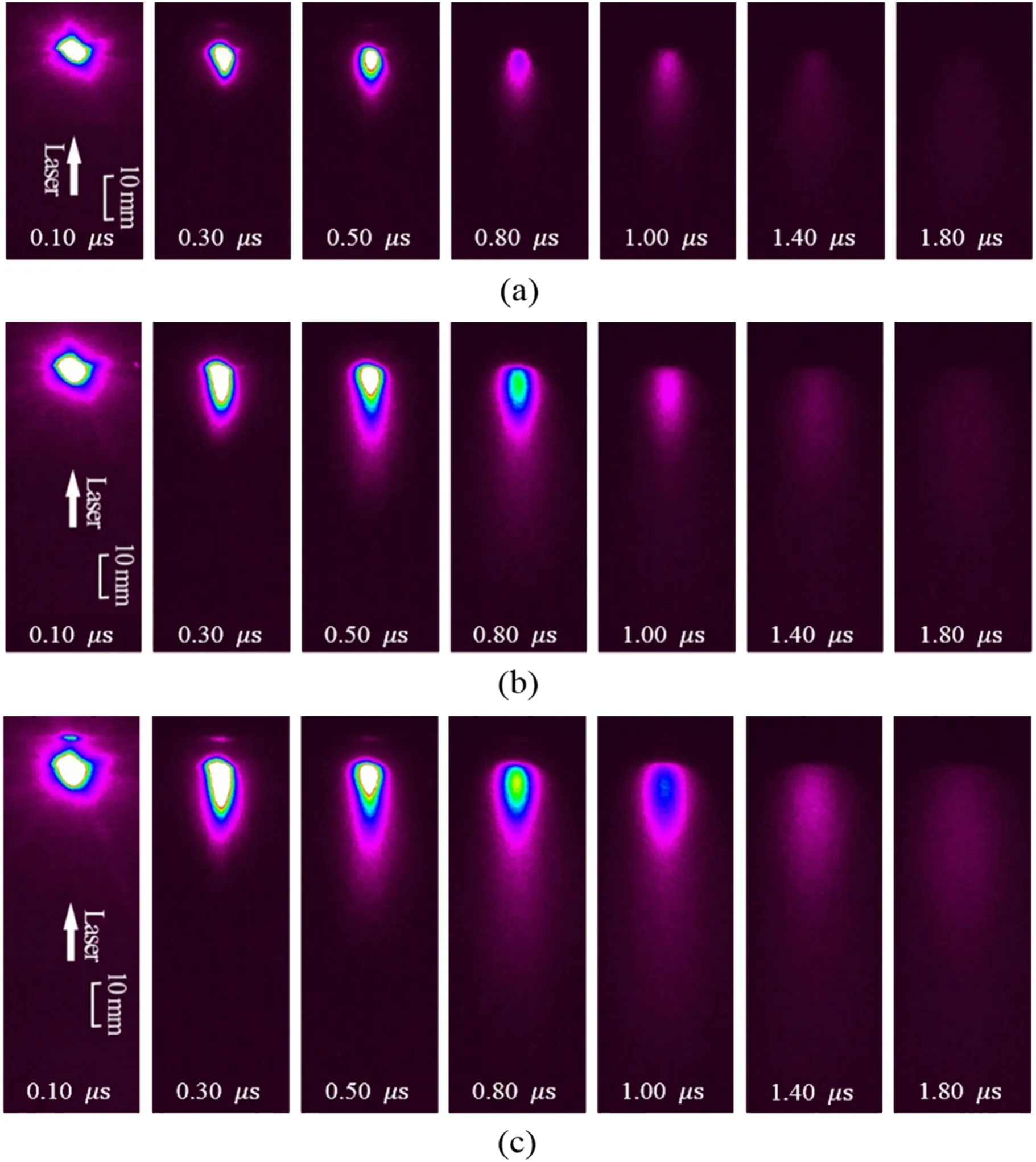
Figure 13.Relationship between the light intensity and the distance on the symmetry axis of aluminium alloy plasma.
According to the time-resolved images of the aluminium alloy plasma plume in figure 12(a), from 0.20 to 0.35 μs, in gas background at 5 Pa, the interaction between the plumes’leading edge and the background gas steadily increases.The edge of the interface between the plasma front and the background gas decelerates, indicating the formation of a shock wave [24].With the progression of time, starting from 0.2 μs,the plasma plume separates into two components.One part moves away from the target, whereas the other moves slowly or seems to be stationary;these parts are called the fast and slow components, respectively.The light intensity signal of the aluminium alloy plasma along the symmetry axis of the laser direction is extracted, and the maximum light intensity in the entire plume evolution is used to normalise the acquired data and obtain the relationship between the light intensity and the distance, as shown in figure 13.Two local light intensity peaks can be observed on the dotted line graph corresponding to a time of 0.3 μs; they represent the light intensity peaks of the slow and fast components.The local light intensity peak caused by the fast component can be observed at all five moments in figure 13 and moves further away from the propellant surface over time;this indicates that the fast components are moving away from the target.The local light intensity peak caused by the slow component can be observed from 0.3 to 0.4 μs.Comparing the data of the three time points, it can be concluded that the peak value of the slow component is higher than that of the fast component at 0.3 μs.The peak value of the fast component is approximately identical to and exceeding that of the slow component at 0.35 and 0.4 μs, respectively.
Regarding the plasma plume generated by laser ablation,plume splitting exists under any background pressure, but may not be visible in the plasma plume image [18].This paper refers to the split plume that is visible in the plasma plume image as a visible plume split.For example, using the single pulse ablation mass shown in figure 4 and the plasma plume front velocity shown in figure 11, the kinetic energies of aluminium alloy, red copper, and carbon steel at a laser energy of 542.3 mJ are calculated to be approximately 1.062,1.273, and 1.117 J, respectively, which are greater than the input laser energy.When the laser light interacts with the propellant, the energy is partially reflected and partially transmitted or transferred into the operation medium.In addition, there is energy loss, including thermal radiation;thus,the total kinetic energy obtained by the plasma plume is lower than the laser energy.However, assuming that all ablated working fluids have the same velocity as the plasma plume front, the total kinetic energy is approximately twice the input laser energy, which indicates that there must be numerous particles with lower velocity in the plasma plume.Therefore, even when the background pressure is extremely low, there are different particles with different velocities in the plasma plume,leading to plume splitting.Bulgakoveet alobserved plume splitting in a vacuum using the time-of-flight technique [25].
Plume splitting exists at any background pressure,which is determined by the complex laser ablation.There is no consensus on the interpretation and description of plume splitting.We analysed the plume splitting caused by laser ablation from the perspective of macro-heating.During laser ablation, the target was gradually heated to increase its temperature.Although the interior of the target was also heated owing to the laser light transmission and heat conduction, the laser energy was primarily concentrated on the surface of the target.Therefore, the heating of the target surface was the fastest, triggering phase transformation,evaporation,boiling,and other processes.A part of the target surface was first ablated, and the propellant surface was left.In the process of outward movement, the plasma had a shielding effect of the laser light and continued to absorb the laser energy; thus, it continuously heated, ionised, and accelerated.Therefore, the particles moved outward at a faster speed and formed the fast component.Subsequently,the inner surface of the target was heated, ionised, and accelerated owing to heat conduction, laser energy absorption, and radiation heat transfer of the fast component,forming the slow component.
The visible plume splitting and forming conditions are relatively harsh, and for some materials, they can only be formed under a certain background pressure.Amorusoet al[26] reported that visible plume splitting occurs during the formation of the plume–background gas contact front, but before the plume expansion is significantly braked.This is because an apparent feature of visible plume splitting is that two different luminous regions can be observed in the plume.Two conditions must be satisfied for the luminescent region represented by the fast component to exist.First, the plasma plume must have a substantial interaction with the background gas allowing strong light emission to occur at the front of the plume–background gas contact, accompanied by the formation of a strong shock wave.At a low background pressure, the interaction between the plasma plume and the background gas is not sufficient to form strong light emission,owing to a low amount of background gas, and plume splitting is not visible.Second, the plasma must travel a long distance to separate the fast and slow components.The plasma movement is limited by the background gas at a higher background pressure, resulting in a shorter movement distance; therefore, the fast and slow components cannot be distinguished.
As shown in figure 12, visible plume splitting cannot be observed in the plasma plumes of red copper and carbon steel under a background pressure of 5 Pa.For red copper and carbon steel plasmas,because their kinetic energies are higher than that of aluminium alloy plasma, a higher background pressure is required to form stronger light emission and shock waves at the front of the plume–background gas contact.Therefore, the background pressure for forming visible plume splitting is higher than that of aluminium alloy.For background argon gas,visible plume splitting was observed for aluminium[18] and copper [27] at 20 and 23 Pa, respectively.No visible plume splitting was observed for iron under pressure conditions<20 Pa and >300 Pa; however, visible plume splitting was observed under 50–200 Pa [18, 28].For background helium gas, visible plume splitting can be observed for aluminium at 0.133 Pa [29].Therefore, the background pressure range of visible plume splitting is highly dependent on the material and the background gas composition.
The shock wave generated when the laser plasma plume expands in gas background at a specific pressure has been investigated previously [30].The leading-edge position thatchanges over time conforms to the Sedov–Taylor (S–T)theory.Table 3 for summarising the experimental results has been given.
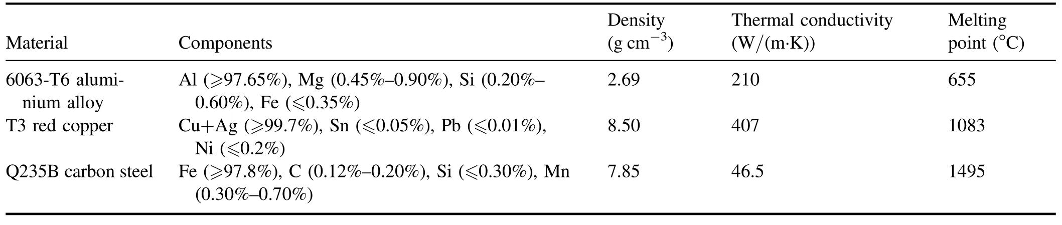
Table 1.Composition and basic properties of propellants.
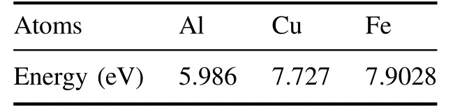
Table 2.First ionisation energy of selected atoms.
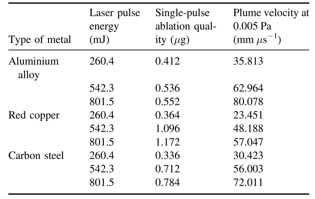
Table 3.Summary of experimental results.
4.Conclusions
After detailed analysis of the ablation quality, morphology,and plume distribution of various metals, the following conclusions were reached.
The ablation morphology and plume distribution of red copper were more uniform, and the ablation quality was higher,suggesting that red copper is more suitable for LAPPT than the other tested metals.
The leading-edge length of the plasma plume in gas background at 0.005 Pa is proportional to the time under different input laser pulse energies, and the plume forward expansion velocity increased with laser energy.Among the three metals, the velocity of the plasma plume front of aluminium alloy was the highest, indicating that the response time of the thruster with aluminium alloy as the propellant was shorter.When the background pressure was 5 Pa,a shock wave was formed at the junction of the plume leading edge and the background gas and the Sedov–Taylor(S–T)theory can describe the plume leading-edge position.A visible plume splitting phenomenon was observed in the aluminium alloy plasma plume in gas background at 5 Pa and 542.3 mJ laser energy.Through comprehensive analysis, it is concluded that the plume splitting phenomenon exists under any background pressure, and the inevitability of the plume splitting phenomenon is analysed from a macroscopic heating point of view.The appearance of plume splitting indicates that the propellant enters the discharge acceleration channel at different moments when the propellant is supplied to the thruster by laser ablation.Therefore, to improve the thruster performance, plume splitting should be considered when designing a thruster.
Acknowledgments
This research was supported by National Natural Science Foundation of China (No.11772354).
猜你喜欢
环球时报(2022-08-02)2022-08-02
Plasma Science and Technology(2022年7期)2022-08-01
青春期健康·家庭版(2022年1期)2022-02-03
Plasma Science and Technology(2021年2期)2021-02-27
作文大王·低年级(2020年12期)2020-12-31
江苏教育·书法教育(2020年10期)2020-09-10
当代人(2020年4期)2020-05-08
中华诗词(2019年9期)2019-05-21
思维与智慧·上半月(2018年4期)2018-04-09
美与时代·城市版(2016年9期)2016-05-14
 Plasma Science and Technology2021年10期
- Plasma Science and Technology的其它文章
- Numerical study of the grid erosion of field emission electric propulsion
- Investigation of variable aperture on the performance and lifetime of ion thruster
- Experimental study of a porous electrospray thruster with different number of emitterstrips
- Design and fabrication of a full elastic submicron-Newton scale thrust measurement system for plasma micro thrusters
- A plasma equilibrium model for rapid estimation of SF-MPDT performance
- Numerical simulation of the effects of protrusion on DC arc anode attachment