
Investigation on current loss of high-power vacuum transmission lines with coaxial-disk transitions by particle-in-cell simulations
2021-11-30 08:29WeiLUO罗伟JianweiZHANG张建威YongdongLI李永东HongguangWANG王洪广ChunliangLIU刘纯亮PengfeiZHANG张鹏飞andFanGUO郭帆
Plasma Science and Technology 2021年11期
关键词:鹏飞
Wei LUO (罗伟), Jianwei ZHANG (张建威), Yongdong LI (李永东),Hongguang WANG (王洪广), Chunliang LIU (刘纯亮),Pengfei ZHANG (张鹏飞) and Fan GUO (郭帆)
1 Department of Applied Physics, Xi’an University of Technology, Xi’an 710048, People’s Republic of China
2 Key Laboratory for Physical Electronics and Devices of the Ministry of Education, School of Electronic Science and Engineering, Xi’an Jiaotong University, Xi’an 710049, People’s Republic of China
3 State Key Laboratory of Intense Pulsed Radiation Simulation and Effect, Northwest Institute of Nuclear Technology, Xi’an 710024, People’s Republic of China
4 Institute of Fluid Physics,China Academy of Engineering Physics,Mianyang 621900,People’s Republic of China
Abstract Coaxial-disk transitions can generate non-uniform magnetic fields and abrupt impedance variations in magnetically insulated transmission lines (MITLs), resulting in disturbed electron flow and non-negligible current loss.In this paper,3D particle-in-cell simulations are conducted with UNPIC-3d to investigate the current loss mechanism and the influence of the input parameters of the coaxial-disk transition on current loss in an MITL system.The results reveal that the magnetic field non-uniformity causes major current loss in the MITL after the coaxialdisk transition,and the non-uniformity decreases with the distance away from the transition.The uniformity of the magnetic field is improved when increasing the number of feed lines of a linear transformer driver-based accelerator with coaxial-disk transitions.The number of input feed lines should be no less than four in the azimuthal distribution to obtain acceptable uniformity of the magnetic field.To make the ratio of the current loss to the total current of the accelerator less than 2%at peak anode current,the ratio of the current in each feed line to the total current should be no less than 8%.
Keywords: magnetically insulated transmission line, coaxial-disk transition, current loss
1.Introduction
High-power soft x-ray radiation generated by fast Z-pinch accelerators provides a solution for driving the hohlraum during inertial confinement fusion [1].Conventional Z-pinch accelerators,such as the ZR accelerator [2] and Primary Test Stand[3], consist of Marx generators, water lines, vacuum insulator stacks and magnetically insulated transmission lines (MITLs)[4].A large number of these subassemblies prevent conventional accelerators from attaining a high repetition rate,which results in a huge volume,and causes considerable energy loss during pulse formation and transmission.The recent development of linear transformer driver (LTD) technology provides a new method for constructing compact and flexible high-current pulsed accelerators that require no water tanks or vacuum insulator stacks [5].Motivated by these advantages,researchers have recently proposed conceptual designs for LTD-based accelerators,such as the Z-IFE and ZP-3R systems(Sandia National Laboratories) [6, 7] and the 5 and 50 MA systems (Chinese Academy of Engineering Physics) [8, 9].
Despite the advantages of LTD-based accelerators,transmitting and coupling high-energy-density pulsed power from the driver to the Z-pinch load are associated with numerous difficulties.Current loss caused by the coaxial-disk transitions of the MITLs is one of the most fundamental problems that must be addressed.Unlike the vacuum insulator stacks separating the MITLs from the water lines and drivers in conventional systems, coaxial-disk transitions connect the MITLs to the drivers and transfer the combined pulsed power from tens of drivers to the disk MITLs under vacuum [10].However, the non-uniform structure of the coaxial-disk transitions can lead to non-uniform magnetic fields and abrupt variation of the MITL impedance, which results in disturbed electron flow and current loss [11, 12].Previous research under the JUPITER and LMF projects suggests a total current loss of approximately 10%–15% in long MITLs due to front pulse erosion and losses in the transition region due to magnetic nulls [6, 13].
Researchers have devoted considerable effort to enhancing the current efficiency in coaxial-disk transitions of MITLs.In the conceptual design of the 60 MA Z-IFE driver from Sandia National Laboratories[7],Langston and Pointon found that 70 coaxial MITLs merging into the disk resulted in an electron current ranging from 10–40 MA, causing a large current loss and energy deposition at the anode.Therefore,they proposed a revised design with ten coaxial MITLs to deliver 60 MA to the load.However, the mechanism of current loss due to coaxial-disk transitions of LTD-based accelerators has not been investigated, and the input coaxial MITLs were arranged in a square configuration, which is not consistent with the cylindrical geometry used in experiments.MITLs with coaxial-disk transitions are also used in Angara 5-1[14],although the current loss has only been measured in the coaxial MITLs before the transition, and the current loss in and after the coaxial-disk transitions has not yet been studied.Zou et al experimentally investigated MITLs with coaxial-conical transitions in the Primary Test Stand [15],which were located near the load rather than the drivers.The conceptual designs of the 5 and 50 MA LTD-based accelerators [8, 9] from the Chinese Academy of Engineering Physics use coaxial-disk transitions to converge the pulsed power from the LTD modules, although the current loss caused by the coaxial-disk transition has not been analyzed.In LTD-based accelerators for inertial confinement fusion with electron currents of tens of megaamperes, tens of coaxial-disk transitions required will result in non-negligible current loss.Elucidation of the current loss mechanism and the influence of structure parameters on the current loss is imperative for the construction of next-generation accelerators.
In this study, 3D particle-in-cell (PIC) simulations using UNIPIC code [16] are performed to investigate the current loss mechanism and the influence of the input parameters of coaxial-disk transitions on the current loss of the MITL system.Previous work by other researchers showed that electrode plasma near the post-hole convolute of the MITL can cause large current loss, which is far away from the coaxialdisk transition [17].Moreover, the anode-to-cathode (AK)gap of the coaxial-disk transition is much larger than the AK gap near the post-hole, which indicates that plasma may influence the current loss of the coaxial-disk transition less than that near the post-hole.Therefore,the current loss caused by the coaxial-disk transition is assumed to be electron current loss.Section 2 presents the structure and simulation parameters for a 10 MA conceptual LTD-based accelerator with two feed lines.Section 3 discusses the PIC simulation results and analysis, focusing on the current loss mechanism and the influence of the structure parameters on the current loss of the studied accelerator.Section 4 presents the conclusion.
2.Simulation model
Figure 1 presents side views of the geometry of the simplified MITL system with coaxial-disk transitions in simulations with UNPIC-3d, which is based on a previous LTD-based conceptual Z-pinch accelerator [6, 8].The region consisting of blue lines denotes the anode, while the orange and red regions denote the cathode.Coaxial MITLs with a length of 0.22 m(from R = 0.67 m to R = 0.45 m)are used to feed the pulsed power.The radii of the anode and cathode of the coaxial MITLs are 5.6 and 4.6 cm, respectively.The coaxial MITLs are connected to the disk MITLs via tapered cathodes inside a vacuum chamber.Then, the structure between the coaxial and disk MITLs forms the transition, as shown in figure 1, which may cause additional current loss due to a non-uniform magnetic field.The radius of the cathode tapers from 4.6 to 3.6 cm in transition.The transition starts at R = 0.45 m and ends at R = 0.4 m.The radius of the vacuum chamber is 0.45 m.The outer edge of the disk MITLs locates at R = 0.4 m,where the AK gap of the upper and lower disk MITLs is 2 cm.For 0.2 m < R < 0.4 m, the AK gap of the disk MITLs varies from 2–1 cm.For R > 0.2 m, the AK gap of the disk MITLs remains constant at 1 cm.Four post-holes are located at R = 7.5 cm to combine the pulsed power from the upper and lower MITLs.The MITL is terminated with a coaxial MITL with an anode radius of 5 cm and a cathode radius of 4.5 cm.The vacuum wave impedance of the MITL varies from the coaxial MITLs to the end of the MITL.The impedance of the coaxial line is approximately 11.8 Ω.In the transition area,the impedance varies from 11.8–2.98 Ω at the upper level and 11.8–2.85 Ω at the lower level, respectively.For 0.2 m < R < 0.4 m,the vacuum impedances of the upper and lower MITLs are 2.98 and 2.85 Ω, respectively.For R > 0.2 m, the impedance of the upper MITL varies from 2.98–10.8 Ω and the impedance of the lower MITL varies from 2.85–9.8 Ω.
Although the impedance of the Z-pinch load is timevarying,a resistance load with an impedance of 0.1 Ω is used to simplify the simulations.In the simulations of the twoinput LTD-based accelerator, Cartesian coordinates and adaptive meshes are applied for gridding the model to ensure a sufficient number of grid cells across the AK gap.The number of grid cells and maximum number of particles are approximately 4 × 10⁷and 2 × 10⁷, respectively.A simple input voltage wave, V =V0sin(w t) is used to drive the coaxial feed lines.w =2π /(556 ´ 10-9s)and the rise time of the voltage is 120 ns.The value ofV0is about 3 MV in the simulations with two feed lines and is adjusted with the number of feed lines to keep a load current of 10 MA.This study is aimed at the current loss caused by electron flow due to coaxial-disk transitions.Therefore, the electrode plasma is neglected.The space-charge-limited emission of electrons on the cathode turns on the cathode when the electric field strength exceeds 107V m−1.

Figure 1.Side views of the MITL system from the coaxial MITLs to the load in a two-input LTD-based accelerator in the(a)YZ plane and(b)XZ plane.Region consisting of blue lines denotes the anode, while the orange and red regions represent the cathode.
3.PIC simulation results and analysis
3.1.Current loss mechanism in the coaxial-disk transition
3D PIC simulations are performed with UNPIC-3d to investigate the current loss mechanism in the coaxial-disk transitions of the two-input LTD-based accelerator.The voltage amplitude is about 1 MV at the load.Since the vacuum impedance of the MITL near the load approximates 10 Ω,whereas the load impedance is only 0.1 Ω, the MITL almost operates under short-circuit conditions.In figure 2, the curve of anode current Ialabeled‘coaxial MITL’represents the sum of the input current of the coaxial MITLs.The curves in figure 2 show that the peak anode current is about 9.7 MA at 100 ns, and the current loss mainly occurs before 40 ns.
Figure 2.Current waveforms at various positions from the input coaxial line to the load.
Figure 3 presents the current loss (Ialoss) in different regions of the MITL, which is caused by the loss of electron flow.The total current loss is composed of the current losses in the coaxial MITL, the chamber wall and the disk MITLs.The current waveforms indicate that the current loss mainly occurs in the region from the input coaxial line to the middle of the disk MITL.Results reveal that the total current loss reaches a peak value of 840 kA at 22 ns.Then, the total current loss decreases to 130 kA at 100 ns, which is approximately 1.34% of the total current.The current losses of the coaxial MITLs, chamber wall and transition are negligible when compared with the total current loss.As figure 4 shows, prior to 20 ns, the current loss of the upper MITL is almost equal to that of the lower MITL.However, after this point the situation changes as the current loss of upper MITL decreases while the current loss of lower MITL continues to increase.After 28 ns, the current loss of the lower MITL decreases but remains considerably higher than that of the upper MITL.This behavior may be caused by the difference between the magnetic field of the upper and lower MITLs.
To clarify the region where electron loss occurs, the electron particle plots in the XZ plane are presented in figure 5.The results indicate that when the electron flow in the coaxial MITLs enters the coaxial-disk transition(regions a and b),the electron flow is disturbed due to the abrupt change in the structure of the MITL.Therefore, the boundary of the electron flow extends to the anode in regions a and b.Regions c and d locate in the middle of two adjacent coaxial MITLs.The electron layers in regions c and d extend to the anode of the vacuum chamber, which may be attributed to the weakened magnetic field in these regions.Figures 6 and 7 present the magnitudes of the magnetic and electric fields, respectively.The results show that the magnetic field magnitudes near the transitions (regions a and b) are considerably higher than those in the region between the input coaxial MITLs(regions c and d).In contrast, the electric field magnitudes in the disk MITLs are more uniform than the magnetic fields along the angular loop.Consequently, the emitted electron current in regions c and d is almost equal to that near the transitions, whereas the magnetic fields near the transitions are higher than those far away from the transitions (regions c and d).Therefore, the emitted electrons are not well magnetically insulated in regions c and d due to the weak magnetic fields [12].
Although figure 6 shows the contour of the magnetic field, the plots of the magnetic field at different azimuthal angles need to be analyzed.Figure 8 shows the azimuthal magnetic field distributions of the upper MITL at 22 and 100 ns.The magnetic field magnitudes reach their maximum values at the positions located on the line directed from the transition to the load(0°and 180°)and their minimum values at the positions located between the two transitions (90° and 270°).As shown in figure 8(a), when R = 0.44 m and t = 22 ns,the magnetic field magnitude reaches a peak value of 6 T and declines exponentially to 0.07 T within±30°of the transition center(0°and 180°).The results in figures 8(a)and(b) indicate a highly non-uniform magnetic field near the vacuum chamber.
In figure 9, the black lines, red lines and blue lines represent the magnetic fields along the paths from the input coaxial line to the load at 0° (maximum value), the magnetic fields at 90° (minimum value) and the critical magnetic field for magnetic insulation, respectively.Therefore, the difference value between the magnetic field at 0° (max value) and 90° (minimum value) shows the non-uniformity of the magnetic field,which indicates that the non-uniformity of the magnetic field decreases with the increase in distance away from the transition.The curves also indicate that the magnetic field non-uniformity reaches its largest value in the middle of the transition.Figures 9(a)and(b)show the magnetic field of the upper MITL and lower MITL from the input coaxial line to the load at 22 ns, respectively.The curves reveal that the magnetic field at 0°(black solid lines)is much larger than the critical magnetic field, while the magnetic field at 90° (red dash lines) is smaller than the critical magnetic field for magnetic insulation, which causes current loss, as shown in figures 3 and 4.Figures 9(a) and (b) show the magnetic field of the upper MITL and lower MITL from the input coaxial line to the load at 100 ns,respectively.The results of figure 9 indicate that the minimum magnetic field (90°) at 100 ns exceeds the critical magnetic field for magnetic insulation and causes much less current loss than that at 22 ns,which can be seen in figures 3 and 4.

Figure 3.Current loss in various sections from the input coaxial line to the middle of the disk MITL.
3.2.Influence of input parameters on current loss
LTD-based accelerators with currents of tens of megaamperes are commonly powered by several to tens of feed lines.To investigate the influence of the input parameters on the current loss of an LTD-based accelerator with coaxial-disk transitions, simulations of a 10 MA LTD-based accelerator are performed.As plotted in figure 10(a), the maximum current loss increases slightly with the number of feed lines,N.The current loss at the peak current (t = 100 ns) remains almost unchanged and increases slowly for N > 8.For N = 16,the maximum current loss is approximately 1.51 MA and the current loss at the peak current is approximately 0.42 MA.This phenomenon may be caused by decreased current in each single line and too many transitions in the process of power converging [7].Figure 10(b) shows the ratio of the current loss to the total current of the accelerator,as a function of the ratio of the current in each feed line to the total current,IN/It.The results reveal that a higher current for each feed line leads to a lower current loss.The hollow and solid data represent the PIC simulation results in this work and results in [7] by Langston and Pointon [7], respectively.It is shown that the results in [7] agree well with the variation trend of/Itobtained in our simulations.In the conceptual design of the 60 MA LTD-based accelerator proposed by Langston and Pointon,IN/Itis about 11.7%, while the maximum value of/Itand/Itat peak anode current are about 9.7%and 1.7%,respectively[7].Therefore,to makeat peak anode current less than 2% when designing a 10–60 MA LTD-based accelerator with coaxial-disk transitions of MITLs,the ratio of the current in each feed line to the total current,IN/It,should be no less than 8%.
Figure 5.Electron particle plots in the XZ plane of the MITL at (a) 40 ns and (b) 100 ns.

Figure 6.Magnetic field magnitudes in the XZ plane of the MITL at (a) 40 ns and (b) 100 ns.

Figure 7.Electric field magnitudes in the XZ plane of the MITL at (a) 40 ns and (b) 100 ns.
Figure 4.Current losses in various sections of the (a) upper MITL and (b) lower MITL.
Figure 8.Azimuthal magnetic field distributions in the YZ plane of the upper MITL at (a) 22 ns and (b) 100 ns.

Figure 9.Magnetic field magnitudes along the paths from the input coaxial line to the(a)upper disk MITL at 22 ns,(b)lower disk MITL at 22 ns, (c) upper disk MITL at 100 ns and (d) lower disk MITL at 100 ns.
As figures 6 and 8 show, coaxial-disk transitions can cause a non-uniform magnetic field.Figure 11(a)displays the azimuthal magnetic field distributions of the upper MITL for four feed lines.Fluctuations in the magnetic field of the MITL are observed, and the azimuthal distribution of the magnetic field with parabolic shape transforms to cosine shape from R = 0.4 m to R = 0.2 m, which illustrates the magnetic field non-uniformity of LTD-based accelerators with coaxial-disk transitions of MITLs.The magnetic field non-uniformity can be defined asδ= (Bmax-Bmin) /(Bmax+Bmin)[12], whereBmaxandBminare the maximum and minimum values of the magnetic field, respectively.Figure 11(b) shows that the azimuthal magnetic field non-uniformity (R = 0.4 m and R = 0.2 m) decreases with an increasing number of feed lines.For N = 2, the magnetic field non-uniformity is nearly 0.6 at R = 0.2 m, which results in large non-uniformity of magnetic field at the load,as shown in figure 9.When N = 4,the magnetic field non-uniformity at R = 0.2 m is about 0.085, which makes the non-uniformity of the magnetic field at the load acceptable.For N = 8, the magnetic field nonuniformity is almost zero at R = 0.2 m, indicating a uniform current distribution in the MITL near the load.However, the magnetic field non-uniformity at R = 0.4 m is still approximately 0.8 for eight feed lines, and it decreases to 0.3 for 16 feed lines.The distribution of the magnetic field non-uniformity shows the difference between the maximum and minimum magnetic field in the azimuthal loop, which may change little for accelerators with different total currents of tens of megaamperes.Therefore, the dependency of nonuniformity of the magnetic field on the number of feed lines shown in figure 11(b) can approximately be a general tendency for LTD-based accelerators with coaxial-disk transitions.To obtain a minimum margin of acceptable uniformity of a magnetic field, the number of input feed lines for an LTD-based accelerator with coaxial-disk transitions should be no less than four in azimuthal distribution.Combining the results in figures 10 and 11,we can suggest that increasing the number of feed lines can decrease the magnetic field nonuniformity, but it can also cause higher current loss.Researchers should seek to achieve a balance between the current loss and the magnetic field uniformity.
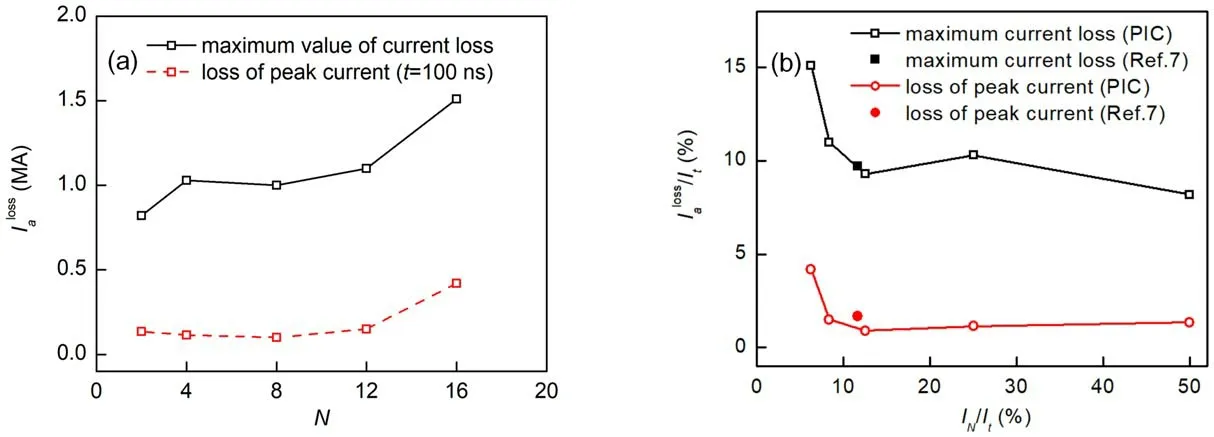
Figure 10.Ratio of current loss to total current of the MITL as functions of(a)number of feed lines and(b)the ratio of current in single feed line to total current.

Figure 11.Plots of(a)the magnetic field as functions of the azimuthal angle with four feed lines at peak current and(b)non-uniformity of the magnetic field as functions of the number of feed lines.
4.Conclusion
In this study, the current loss in coaxial-disk transitions of MITLs is investigated with 3D PIC simulations.The current loss mechanism in coaxial-disk transitions is studied, and the influence of the input parameters on the current loss is evaluated.The results reveal that the non-uniform magnetic field distribution causes continuous current loss when the electron flow enters the coaxial-disk transition.The current loss mainly occurs in the MITL after the coaxial-disk transition.Although the dependency of non-uniformity of a magnetic field on the number of feed lines and the relationship between current loss and input current are obtained with a 10 MA LTD-based accelerator, there can approximately be general rules for LTD-based accelerators with coaxial-disk transitions.Therefore, to make the ratio of the current loss to the total current of the accelerator,/It,less than 2% at peak anode current, the ratio of the current in each feed line to the total current,IN/It,should be no less than 8%when designing a 10–60 MA LTD-based accelerator with coaxial-disk transitions of MITLs.The magnetic field non-uniformity is the highest in the middle of the transition and decreases with the distance away from the transition.To obtain a minimum margin of acceptable uniformity of magnetic field,the number of input feed lines for the LTD-based accelerator with coaxial-disk transitions should be no less than four in azimuthal distribution.Future work will focus on the current loss caused by plasma formation and evolution in the MITL system.
Acknowledgments
This work was supported by National Natural Science Foundation of China (Nos.U1530133 and 52007152), the Special Foundation of State Key Laboratory of Intense Pulsed Radiation Simulation and Effect (No.SKLIPR2005) and the Youth Innovation Team of Shaanxi Universities.
猜你喜欢
金桥(2022年6期)2022-06-20
华人时刊(2022年7期)2022-06-05
成功营销(2021年8期)2021-03-23
Plasma Science and Technology(2021年1期)2021-03-01
老年博览·上半月(2020年3期)2020-09-22
书香两岸(2020年3期)2020-06-29
老年博览·上半月(2020年1期)2020-02-10
杂文月刊(2019年18期)2019-12-04
老年博览·上半月(2019年2期)2019-09-10
初中生世界·七年级(2019年6期)2019-08-17
 Plasma Science and Technology2021年11期
- Plasma Science and Technology的其它文章
- Spatial and temporal evolution of electromagnetic pulses generated at Shenguang-II series laser facilities
- Numerical study on the loss of fast ions produced by minority ion cyclotron resonance heating in EAST
- Machine learning of turbulent transport in fusion plasmas with neural network
- Observation of coherent mode induced by a molybdenum dust on EAST
- Investigation of stimulated Raman scattering in longitudinal magnetized plasma by theory and kinetic simulation
- The influence of magnetic field on the beam quality of relativistic electron beam long-range propagation in near-Earth environment