
Morphological effect on electrochemical performance of nanostructural CrN∗
2021-12-22 06:43ZhengweiXiong熊政伟XuemeiAn安雪梅QianLiu刘倩JiayiZhu朱家艺XiaoqiangZhang张小强ChenchunHao郝辰春QiangYang羊强ZhipengGao高志鹏andMengZhang张盟
Chinese Physics B 2021年12期
Zhengwei Xiong(熊政伟) Xuemei An(安雪梅) Qian Liu(刘倩)Jiayi Zhu(朱家艺) Xiaoqiang Zhang(张小强) Chenchun Hao(郝辰春)Qiang Yang(羊强) Zhipeng Gao(高志鹏) and Meng Zhang(张盟)
1Joint Laboratory for Extreme Conditions Matter Properties,Southwest University of Science and Technology,Mianyang 621010,China
2Institute of Electronic Engineering,China Academy of Engineering Physics(CAEP),Mianyang 621900,China
3Institute of Fluid Physics,China Academy of Engineering Physics,Mianyang 621900,China
4Affiliated Hospital,Chengdu University of Traditional Chinese Medicine,Chengdu 611137,China
Keywords: CrN,supercapacitors,metal nitride,nanostructures
1. Introduction
Supercapacitor is an important energy-storage device,presenting a longer lifetime (>105cycles), high power density (> 10 mW/cm2), and rapid charge/discharge capabilities safely. Nowsdays,commercial supercapacitors have been widely used in heavy-duty vehicles, load-leveling systems,and hybrid platforms. However, the common energy density of supercapacitors (∼5 Wh/kg) was still lower than that of batteries (up to 200 Wh/kg) or fuel cells (up to 350 Wh/kg).[1]In the past decades, much efforts have been paid for improving the storage performance for supercapacitors. Transition metal nitrides (TMNs) were extensively investigated for many applications,such as electrocatalytic water splitting,[2]plasmonics,[3]and supercapacitors,[4]owing to their excellent conductivity, prominent thermal/chemical stability and outstanding electrochemical performance. Various TMNs, including nickel nitride,[5]titanium nitride,[6]vanadium nitride,[7,8]and molybdenum nitride,[9]have been explored as novel electrode materials for supercapacitors,showing superior specific capacitance and rate performance.In particular,chromium nitride(CrN)with a high resistance to wear and corrosion shows a promising advantage over conventional transition metal oxides in energy storage.[10–13]Lots of synthetic approaches to nanostructured CrN have been reported including physical vapor deposition, nanopatterning, and DC magnetron sputtering. Daset al.synthesized CrN nanoparticles with the size of 20 nm–30 nm by using the combination of a hydrothermal method and a nitridation process, showing a specific capacitance of 75 F/g at the current density of 30 mA/g.[11]Hayeet al.prepared CrN films by magnetron sputtering at glancing angle (GLAD), and obtained a high areal capacitance of 35.4 mF/cm2at 1.2 mA/cm2.[14]Weiet al.reported a high areal specific capacitance(12.8 mF/cm2at 10 mV/s)of CrN thin films prepared by DC magnetron sputtering technology, and the CrN thin film also exhibited high cycling stability with 92.1% capacitance retention after 2×10⁴cycles in the H2SO4electrolyte(0.5 M).[10]However, the reported specific capacitance of CrN was still relatively low,as a disadvantage of TMNs based supercapacitor,comparing with metal oxides,mxenes or transition metal phosphides.[15]
The morphology and size are critical factors in determining the electrochemical performance of the supercapacitor materials with a single component, due to the manifestation of the nanosize effect. As we know, the morphology, size, and synthetic method of TMNs may remarkably improve the number of redox centers and enhance their supercapacitor performance. For example, two-dimensional nanomaterials with a large specific surface area facilitate interfacial reactions in supercapacitors, rechargeable batteries, as well as catalysts.[16]Due to the unique structure, the obtained free-standing TiN nanosheet arrays have a large specific capacitance of 81.63 F/g and excellent cycling performance without capacitance decay after 2500 cycles.[17]Huoet al. synthesized VN nanoflakes from nitriding V2O5nanoflakes xerogel,resulting in the large nanoflake morphology of VN with porous structure. The VN material had a high specific capacitance of 152 F/g at 1 A/g in the alkaline solution.[18]However,the effect of morphology and size for the CrN material on the supercapacitor was rarely studied, as far as we know. Herien, three nanostructures of the CrN material were studies for their electrochemical properties in this work, basing on the Cr2O3precursors with different morphologies. The obtained CrN nanostructures, including (i) hierarchical microspheres assembled by nanoparticles, (ii) microlayers, and (iii) nanoparticles, were prepared by the combination of a thermal-nitridation process and a template (Cr2O3) technique. As a result, high-temperature nitridation could not only transform the hexagonal Cr2O3into cubic CrN completely, but also keep the template’ morphology unchanged. The electrochemical performance of CrN nanostructures assembling into supercapacitors was systematically tested and discussed.
2. Experimental details
2.1. Preparation of Cr2O3 precursor
(i)The microspheres Cr2O3precursor was synthesized by a modified hydrothermal method.[19]Briefly, 0.8-mmol glucose and 0.1-mmol Cr(NO3)3·9H2O were dissolved in 40-ml and 20-ml deionized water, respectively. The two solutions were then mixed and placed in 100 ml of teflon liner coated with a stainless steel autoclave. After keeping the temperature at 180◦C for 24 h,a black precipitate was obtained. Then,the powders were washed with deionized water and alcohol three times,and dried in a drying oven at 60◦C for 5 h. Finally,the powders were heated up to 550◦C for 4 h in a muffle furnace at an atmosphere. (ii)The Cr2O3microplates precursor was synthesized by a method reported previously.[20]Firstly, 15 mL of Cr(NO3)3solution (0.1 mol/L) was heated to 70◦C under magnetic stirring. Then, the ammonia solution was added to the above solution dropwise,until the pH=9. The suspension was kept at room temperature for 1 h. Finally, it was washed with deionized water,and then dried under reduced pressure at 140◦C in a drying cabinet. (iii)The Cr2O3nanoparticle precursor was synthesized by a simple annealing method. Firstly,1 mmol of CrCl3·6H2O and 3 mmol of propylene oxide were stirred in 40 mL of DI water in a breaker to form a gel. Then,the obtained gel was placed in an aluminum oxide crucible,and heated to 600◦C. The state was kept for 1 hour in the atmosphere,and the product was obtained.
2.2. Preparation of CrN nanostructures
By using the above-mentioned three Cr2O3precursors with different morphologies, we obtained three different nanostructural CrNs respectively. Briefly, 2.0 g of the above three kinds of Cr2O3powders were loaded into a crucible,respectively,and heated to 800◦C in an ammonia(NH3)atmosphere. The NH3flow rate was 0.06 m3/h, and the process was kept for 4 h. Then, the system was naturally cooled to room temperature. Note that NH3was introduced for 0.5 h before the temperature rise,ensuring that the air in the furnace was fully eliminated. The generated tail gas was absorbed by dilute H2SO4solution. The schematic diagram of CrN preparation was shown in Fig.1.
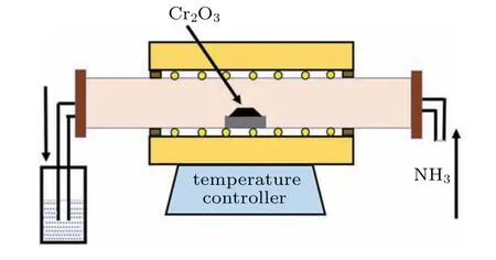
Fig.1. Schematic diagram of CrN fabrication.
2.3. Structure characterization
All the samples used an x-ray diffractometer (XRD) to test the crystal structure of the material.The x-ray source is Cu targetKαradiation(λ=0.154 nm), the 2θmeasuring range is 10◦–80◦, and the scanning rate is 8◦/min. The micromorphology of the samples was observed at high magnifications such as 104(10 kx)and 5×10⁴(50 kx)with a high-resolution cold field emission scanning electron microscope(SEM).The chemical bond composition of the products was characterized by x-ray electron spectroscopy(XPS).A transmission electron microscope(TEM)with high-resolution transmission electron microscope(HRTEM)was used to observe the internal structure of the samples. With the Asap2020 chemical adsorption analyzer, the specific surface area of the sample was calculated by the Brunauer–Emmett–Teller (BET) equation of N2adsorption isotherm.
2.4. Electrochemical characterization
The working electrode was fabricated by a slurry-forging method with Ti sheet electrode. Briefly, CrN powders, conductive carbon powders, and polyvinylidene fluoride(PVDF)were mixed uniformly with a mass ratio of 8:1:1. Then,they were added with the N-methylpyrrolidone (NMP) until the mixed powder is ground into a thick slurry. The paste was uniformly coated on one side of the cleaned Ti sheet electrode and then dried in a drying box at 40◦C for 12 h. The cyclic voltammetry curve (CV), constant current charge-discharge curve (GCD), impedance spectroscopy(EIS), and cyclic voltammetry stability of the CrN electrode material were tested through the electrochemical workstation(CHI660E) with a three-electrode system. The as-prepared CrN electrode, Hg/HgO and Pt sheets were used as working electrodes,the reference electrode,and the counter electrode,respectively. The electrolyte was 1-mol/L KOH.According to the CV and GCD curves, the specific capacitance (Cs) of the electrode material could be calculated separately by

whereIis current,mis the material quality,∆Vis the voltage window during the test,vis the scan rate of the CV curves,and∆tis the discharge time. The energy density (E) and power density (P) of the CrN electrode materials was calculated by the following equations

where ∆Vand ∆tare the voltage window and time of discharge,respectively.
3. Results and discussion
First, nanostructural Cr2O3precursors were synthesized with three kind of morphologies with nanoparticles, microlayer, and microsphere. The Cr2O3nanoparticles were generated by high-temperature sintering of the gel formed by chromium trichloride hexahydrate and propylene oxide. Dispersed nanoparticles were found with a relatively uniform size(Figs. 2(a) and 2(b)). The microlayered Cr2O3was obtained by drying chromium nitrate solution under reduced pressure in an alkaline environment(Figs.2(c)and 2(d)). Its surface was composed of Cr2O3nanoparticles bonded and stacked.Importantly, the microspherical Cr2O3was prepared by a reported hydrothermal method, and the spherical Cr2O3surface was loose and porous clearly(Figs.2(e)and 2(f)). Nanostructural CrN electrode materials were obtained by annealing different nanostructural Cr2O3in ammonia atmosphere as shown in the schematic diagram. During the reaction,the oxygen atoms in Cr2O3are replaced by nitrogen atoms,resulting in CrN materials with loose nanostructures. The whole high-temperature ammoniation process is presented by the following formula:

By the combination of the construction of Cr2O3nanostructure precursors with the ammoniating process,CrN materials with different nanostructures were obtained. Compared with the morphologies of the Cr2O3precursors, there are the following differences of as-prepared CrN materials. The size of the CrN nanoparticles was reduced and has no clear edges from the observation of TEM test. The surface of the CrN microspheres is looser (Fig. 3(g)), and the CrN is observed as loose microspheres by TEM observation (Fig. 3(h)). In the cross-section, there are a lot of holes in the CrN microlayers(Fig.3(d)). For CrN nanoparticles,the HRTEM image shows the interplanar spacing of 0.24 nm and 0.21 nm,which is consistent with the cubic CrN (111) and (200) interplanar spacing.[13]For the microlayer and microspherical CrN,the corresponding (200) crystal plane was also found, confirming that high-temperature ammoniation could completely transform transition metal oxides into transition metal nitrides.These unique nanostructures may provide fast transmission channels for electronic transport, thereby improving energy storage performance.
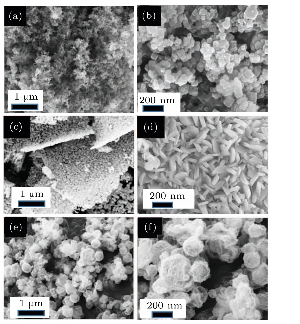
Fig.2. SEM images of Cr2O3 at different magnifications: (a)10 kx nanoparticles;(b)50 kx nanoparticles;(c)10 kx microlayers;(d)50 kx microlayers;(e)10 kx microspheres;(f)50 kx microspheres.
The XRD patterns of CrN nanostructures with different morphologies were shown in Fig. 4(a). The prepared CrN nanostructures have a cubic crystal structure (JCPDS No. 03-065-2899) after hightemperature nitridation.[20,21]High-temperature ammoniation could completely convert hexagonal Cr2O3into cubic CrN,which is consistent with the HRTEM measurement results. Three peaks at 574.5, 575.6,and 586.5 eV were found in Figs. 4(b) and 4(c), which were attributed to the formation of CrN compounds by the reaction between Cr and N during the nitridation process.[22,23]The peak at 396.6 eV in the N 1s spectrum was derived from the Cr-N bond.[24]
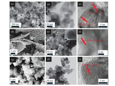
Fig. 3. Morphologies of CrN nanoparticles: (a) SEM, (b) TEM, (c) HRTEM. Morphologies of CrN microlayers: (d) SEM, (e) TEM, (f)HRTEM. Morphologies of CrN microspheres: (g) SEM, (h) TEM, (i) HRTEM. The insets at the upper right of figures [panels (d), (e), (g)]show the magnified view.
XPS measurements were further employed to analyze the element composition and valence states of the CrN sample.XPS experiments confirmed that there were only two elements,Cr and N,in the synthesized CrN sample,which is consistent with XRD analysis. In the high-resolution XPS scan,Cr 2p core splits into 2p 3/2 and 2p 1/2 peaks(575.5 eV and 584.9 eV).The results indicated that Cr element exhibited+3 oxidation states in the sample. On the other hand, N 1s peak was fitted into 396.6 eV,and indexed to the Cr-N bond.[22–24]

Fig.4. (a)XRD patterns of CrN with different nanostructures: nanoparticles(black line),microsphers(red line),and microlayers(blue line). XPS spectra of CrN with(b)Cr 2p and(c)N 1s.
Initially,CrN materials with different morphologies were evaluated by the cyclic voltammetry and current chargedischarge curves in Fig. 5. It could be seen that the rectangular area of the CV curve of the CrN nanoparticles was small at different scan rates, resulting in its small capacitance. By combining with the GCD curve, it could be seen that there is oxidation–reduction reaction during the charge and discharge process. For the microlayered CrN, the CV curve is almost rectangular and has a weak redox peak. Combined with the GCD curve results, it shows that there is a redox pseudocapacitance behavior during the electrochemical behavior. Figure 5(e) shows the CV curve of porous spherical CrN.The redox peak was found obviously,indicating that there is a redox pseudocapacitance behavior during the electrochemical charging and discharging process, which is consistent with the result of the GCD curve. According to the CV and GCD curves,the specific capacitance of the electrode material was calculated (Eqs. (1) and (2)). The specific capacitance decreases with the increase of the scan rate,as CrN electrode material showed a slow transfer and charge diffusion in the KOH electrolyte at a higher scan rate. Within the scan rate range of 10 mV/s–500 mV/s, the specific capacitance drop range of CrN nanoparticles, microlayers, and microspheres were: 82.4 F/g→55.6 F/g, 126.7 F/g→63.2 F/g,213.2 F/g→106.3 F/g respectively, and the corresponding specific capacitance retention rates were 67.5%, 49.8%, and 49.9%,respectively.

Fig. 5. The CV and GCD curves of CrN with different morphologies: (a) nanoparticles CV, (b) nanoparticles GCD, (c) microlayers CV, (d)microlayers GCD,(e)microspherical CV,and(f)microspherical GCD.
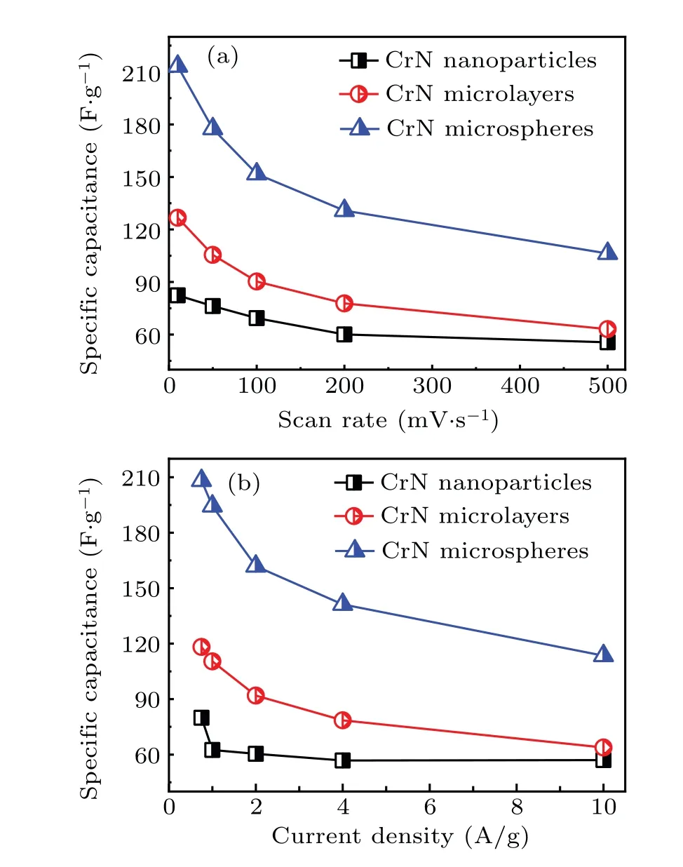
Fig. 6. Specific capacitance of CrN with different nanostructures under (a)different scanning rates and(b)different current densities.
The relationship between current density and specific capacitance was shown in the curves of Fig. 6. As the current density increases, the specific capacitance gradually decreases, which is consistent with the trend between the scan rate and specific capacitance curve. In the current density range of 0.75 A/g–10 A/g, the specific capacitance drop intervals of CrN nanoparticles, microlayers, and microspheres were 79.8 F/g→55.0 F/g, 118.0 F/g→63.8 F/g,208.1 F/g→113.5 F/g, respectively. The corresponding specific capacitance retention rates were 68.9%, 54.1%, and 54.5%, respectively. For the above three different nanostructures of CrN materials, although the CrN nanoparticles had a higher specific capacitance retention rate,the specific capacitance was smaller. In contrast,the porous microspherical CrN had a high specific capacitance with a scan rate of 500 mV/s and 10 A/g,showing a big advantage in the application of supercapacitors.
To probe the conductive property occurring at electrode/electrolyte interfaces, impedance spectra of different nanostructured CrNs were obtained. The impedance curves of CrN nanoparticles,microlayers,and microspheres were approximately vertical, indicating that the three types of CrN nanostructures all exhibit capacitance characteristics. The intercept between the impedance curve of the sample in the highfrequency region and theXaxis can reflect the internal resistance (Rs) of the electrode material. As shown in the insets of Figs.7(a)and 7(c),theRsfor CrN nanoparticles,microlayers, and microspheres were 1.5 Ω, 2.9 Ω, and 0.9 Ω, respectively. Among them,the internal resistance of microlayer CrN was the largest, due to a large number of voids in the crosssection of the microlayered CrN.For microspheres CrN,Rsis significantly smaller than that of other nanostructures, proving porous spherical CrN has the best conductive property. It was even smaller than that of TMOs electrode materials,such as Cr2O3(Rs= 2.3 Ω),[25]MoO3(Rs= 2.22 Ω),[26]V2O5(Rs=1.3 Ω).[27]

Fig.7. EIS plots of CrN with different nanostructures: (a)nanoparticles,(b)microlayers and microspheres. The insets display the impedance spectra in the high-frequency region.
Comparing CrN electrode materials with different nanostructures, the specific capacitance was as follows: 82.4 F/g(nanoparticles)>126.7 F/g (microlayers)<213.2 F/g (microspheres). They were higher than that of other reported CrN electrodes, such as CrN nanoparticles (75 F/g) and CrN film(41.6 F/g).[11,20]The porous microspherical CrN had the biggest specific capacitance, due to the large specific surface area. According to the results of nitrogen adsorption and desorption (Fig. 8(a)), the specific surface areas of as-obtained CrN nanoparticles,microlayers,and microspheres were 13.7,28.6, and 58.1 cm3/g, respectively. Compared with the other two nanostructures, the specific surface area of microspherical CrN was significantly increased. As shown in Fig. 8(b),the capacity retention rate of the porous spherical CrN nanostructure after 5000 cycles in 1-mol/L KOH solution is 96%,demonstrating its excellent cycle stability in strong alkaline electrolytes.

Fig.8. (a)Nitrogen adsorption–desorption isotherms of CrN with different nanostructures. (b)Cycling stability of CrN microspheres at room temperature.(c)Ragone plot of supercapacitors for CrN microsphers,V2O5 nanofibers,[27] V2O5 nanosheets,[29] Co3O4 thin sheets,[30] Mo0.1Ti0.9O2 nanoparticles,[31]MoO2/Mo2N nanobelts,[32] Cr2O3/CrN nanoshells,[13] TiN nanotubes,[33] TiN nanospheres,[34] VN nanowires,[35] and Mo3N2 nanobelts.[28]
By using the Eqs. (5) and (4), we calculated the power density (443.4 W/kg) and energy density (28.9 Wh/kg) of porous spherical CrN. By comparing the energy density and power density of other metal oxide and metal nitride electrode materials,[27–35]porous microspherical CrN had excellent supercapacitor characteristics (Fig. 8(c)). A large number of studies have shown that electrode materials with different nanostructures exhibit different electrochemical properties. In the samples we constructed,the porous spherical CrN exhibits remarkable electrochemical performance,and the reason was summarized:by the following points:(i)A smaller internal resistance can effectively promote the rapid transfer of charges and shorten the charge and discharge time;[36,37](ii)The porous microspherical nanostructure has a larger specific surface area and successfully constructed a three-dimensional electrical charge network to further enhance the charge transfer rate.[38]
4. Conclusion
In this work, we provide a new strategy for the design and development of nanostructural CrN electrode materials with different morphologies (nanoparticles, microlayers, and microspheres). The specific capacitances of the three nanostructured CrNs were: 213.2 F/g (microspheres)>126.7 F/g(microlayers)>82.4 F/g(nanoparticles). Importantly the capacity retention rate of porous CrN microspheres is 96%after 5000 cycles in 1-mol/L KOH solution, and its energy density and power density reached 28.9 Wh/kg and 443.4 W/kg.These characteristics could effectively improve the energy storage characteristics of the electrode material.
猜你喜欢
Chinese Physics B(2022年11期)2022-11-21
地理教学(2022年11期)2022-07-26
交响-西安音乐学院学报(2021年1期)2021-05-29
开发研究(2020年2期)2020-07-30
水动力学研究与进展 B辑(2018年5期)2018-10-27
汉字汉语研究(2018年2期)2018-07-09
商情(2018年10期)2018-03-29
美与时代·美术学刊(2017年6期)2017-07-31
法语学习(2016年5期)2016-12-18
小天使·五年级语数英综合(2016年9期)2016-10-09

- Chinese Physics B的其它文章
- Transient transition behaviors of fractional-order simplest chaotic circuit with bi-stable locally-active memristor and its ARM-based implementation
- Modeling and dynamics of double Hindmarsh–Rose neuron with memristor-based magnetic coupling and time delay∗
- Cascade discrete memristive maps for enhancing chaos∗
- A review on the design of ternary logic circuits∗
- Extended phase diagram of La1−xCaxMnO3 by interfacial engineering∗
- A double quantum dot defined by top gates in a single crystalline InSb nanosheet∗