
Manipulating vortices in F =2 Bose-Einstein condensates through magnetic field and spin-orbit coupling
2022-04-12 03:44HaoZhu朱浩ShouGenYin印寿根andWuMingLiu刘伍明
Chinese Physics B 2022年4期
Hao Zhu(朱浩) Shou-Gen Yin(印寿根) and Wu-Ming Liu(刘伍明)
1Key Laboratory of Display Materials and Photoelectric Devices(Ministry of Education),Tianjin Key Laboratory for Photoelectric Materials and Devices,School of Materials Science and Engineering,Tianjin University of Technology,Tianjin 300384,China
2Beijing National Laboratory for Condensed Matter Physics,Institute of Physics,Chinese Academy of Sciences,Beijing 100190,China
3School of Physical Sciences,University of Chinese Academy of Sciences,Beijing 100190,China
4Songshan Lake Materials Laboratory,Dongguan 523808,China
Keywords: Bose-Einstein condensates,vortex,magnetic field,spin-orbit coupling
1. Introduction
Vortex is one of the most fundamental topological excitations appearing in various fields of modern physics.[1-3]In scalar Bose-Einstein condensates (BECs), the quantized vortex was firstly realized by Ketterle’s group[4]which plays a significant role in systematically studying superfluidity and superconductivity.[5-7]Various novel topological nontrivial structures in spinor BECs have been realized,i.e., vortexbright soliton,[8]8πskyrmion,[9]and carbon-dioxide-like skyrmion.[10]There are many methods for generating vortices in real experiments,including phase imprinting techniques,[11]rotating an anisotropic trap,[12]or stirring the condensate with laser beams.[13]However, with the effort of artificial gauge field in cold atom experiments, Spielman’s group generated vortices by laser control techniques,[14-16]which opens a new gate in manipulating topological excitations from spinor BECs.
In this paper, we apply Dresselhaus-type SOC in theF=2 ferromagnetic BECs under additional Ioffe-Pritchard(IP) magnetic field to generate vortex structures. When SOC is absent,polar-core vortex is excited by magnetic field.When considering SOC,Mermin-Ho vortex is introduced to the system. Moreover, canonical particle currents of polar-core vortex and Mermin-Ho vortex are studied. Through calculating phase winding,magnetization,and degree of phase separation,the evolution of the vortex is discussed when magnetic field is changed. On the other hand,the influence of SOC on the vortex is investigated.
This paper is organized as follows: We first introduce the model Hamiltonian in Section 2.The mean-field ground states ofF=2 BECs with IP magnetic field are studied by numerically minimizing the Hamiltonian function,and the polar-core vortex is discussed in Subsection 3.1. The mean-field ground states ofF=2 BECs with IP magnetic field and SOC are investigated,Mermin-Ho vortex and vortex lattice are discussed in Subsection 3.2.Eventually,Section 4 is devoted to concluding remarks.
2. Model Hamiltonian
In order to thoroughly investigate the properties of the vortex solution, the coupled GP equations (3)-(5) are solved by Crank-Nicolson method.[37]We have verified the stationary state solutions by starting the calculation from a variety of initial conditions,such as the Gaussian-like functions. The density-density interactionc0=50, the spin-exchange interactionc1=-5,and the spin singlet-pairingc2=20 are fixed throughout the whole calculation.
3. Results and discussion
3.1. Ground states with IP magnetic field
We first investigate the vortex solution in the weak interatomic interacting region, where the density-density interactionc0= 50, spin-exchange interactionc1=-5, and spin singlet-pairing interactionc2=20 guarantee the ferromagnetic ground states.[38]When SOC is absent, the weak magnetic field (B= 0.1) can induce a vortex at the edge of the condensate, which is depicted in Fig. 1(a). As indicated by the 2D density profiles of different components(|Ψl|2) in the top panel, there is no vortex core emerging.However, from the phase field picture in the bottom panel,the continuously changed phase gradientsθl(from-πtoπ) indicate there is a vortex penetrating into the condensate from the edge. The corresponding one-dimensional(1D)density projection is exhibited in Fig. 1(b), that there are five Gaussian-type wave packages locating at the center. Additionally,when magnetic field strengthB=1,a polar-core vortex is excited in Fig. 1(c).[39-41]The 2D density profiles (top panel) indicate the ring-shaped density of different components with a vortex core in the center. This polar-core vortex can be determined clearly from the phase profiles(bottom panel), that the phase windings of different components are(ω2,ω1,ω0,ω-1,ω-2)=(2,1,0,-1,-2). The corresponding 1D density projection is exhibited in Fig. 1(d), that the components with opposite magnetic quantum number (|Ψ2〉and|Ψ-2〉,|Ψ1〉,and|Ψ-1〉)are totally overlapped.
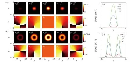
Fig.1. Magnetic field could induce polar-core vortex when SOC is absent. (a)The 2D density profiles of different components when magnetic field strength B=0.1 and SOC strength κ =0(top panel). The corresponding phase fields θl (l=±2,±1,0)are exhibited in the bottom panel. (b)The 1D projection of the density profiles with B=0.1 and κ=0. (c)The 2D density profiles of different components when magnetic field strength B=1 and SOC strength κ=0(top panel). The corresponding phase fields θl are exhibited in the bottom panel. (d)The 1D projection of the density profiles with B=1 and κ =0. In the GP simulation,the dimensionless density-density interaction c0=50,spin-exchange interaction c1=-5,and spin singlet-pairing c2=20. Here,the length of the harmonic trap is ξ0=h¯/(mω⊥).
3.2. Ground states with IP magnetic field and SOC
In the following part, we will consider the combined effect of IP magnetic field and Dresselhaus-type SOC in the weak atomic interaction region of ferromagneticF=2 BECs.When magnetic fieldB=0.25 and SOC strengthκ=0.25,the 2D density profiles and phase fields are depicted in the top panel and bottom panel of Fig. 2(a), respectively. The|Ψ2〉component dominates the center region and resembles bright soliton. Additionally, the|Ψ1,0,-1,-2〉components exhibit ring-shaped distribution with increasing inner diameter. From the phase field in the bottom panel, we can distinguish that the phase windings of different components are(ω2,ω1,ω0,ω-1,ω-2)=(0,-1,-2,-3,-4),which indicates a Mermin-Ho vortex.[42-44]From the 1D density projection in Fig. 2(b) we can identify that the|Ψ2〉component locates in the center, the|Ψ-2〉component locates at the edge and|Ψ1,0,-1〉components locate sandwiched between them.When SOC strengthκ= 1 and IP magnetic field strengthB=0.25, there is a density hole emerging in every component,as shown in the top panel of Fig.2(c). Interestingly,the corresponding phase windings can be distinguished from the phase field in the bottom panel that (ω2,ω1,ω0,ω-1,ω-2)=(-1,-2,-3,-4,-5). Moreover, figure 2(d) shows that the different components with opposite magnetic quantum number (|Ψ2〉and|Ψ-2〉,|Ψ1〉and|Ψ-1〉) are spatially separated which indicates nonzero magnetization.
We can gain further insight into the discussed vortex solution by computing the canonical particle current density of the condensates[45]
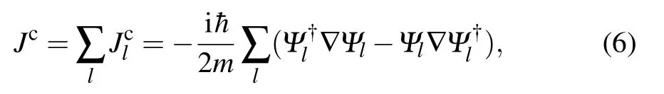
wherel=±2,±1,0 andmrepresents the atom mass. As illustrated in Fig. 3(a), when SOC is absent and magnetic fieldB= 0.1, the canonical particle currentJcpoints toward +ydirection, indicating the condensates are within the plane wave phase.[31]Furthermore, with stronger magnetic field(B=0.25)in Fig.3(b), the canonical particle currentJcapproximates zero. This phenomenon is in good agreement with the phase field of the polar-core vortex shown in Fig.1(c)thatθ-1,-2rotate anticlockwise whileθ1,2rotate clockwise.On the other hand, when SOC strengthκ=1 and magnetic fieldB=0.25 in Fig. 3(c), the canonical particle currentJcrotates anticlockwise. This phenomenon coincides with the MH vortex discussed in Fig. 2(a), inside whichθ-1,0,1,2rotate anticlockwise. Moreover,with the strengthen of magnetic field (κ=1) in Fig. 3(d), the direction of canonical particle currentJcremains anticlockwise while the size of vortex core becomes larger.
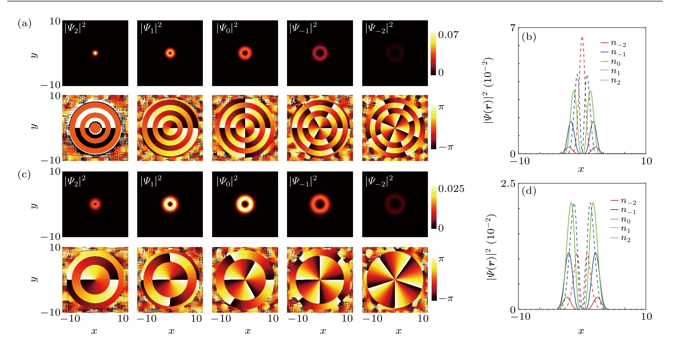
Fig.2. The combined effect of magnetic field and SOC-induced Mermin-Ho vortex. (a)The 2D density profiles of different components when magnetic field strength B=0.25 and SOC strength κ =0.25(top panel). The corresponding phase fields θl (l=±2,±1,0)are exhibited in the bottom panel. (b)The 1D projection of the density profiles when B=0.25 and κ =0.25. (c)The 2D density profiles of different components when magnetic field strength B=0.25 and SOC strength κ =1(top panel). The corresponding phase fields θl are exhibited in the bottom panel. (d)The 1D projection of the density profiles when B=0.25 and κ=1.In the GP simulation,the dimensionless density-density interaction c0=50,spin-exchange interaction c1=-5,and spin-singlet-pairing interaction c2=20. Here,the length of the harmonic trap is ξ0=h¯/(mω⊥).
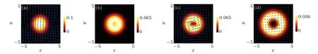
Fig. 3. Canonical particle current Jc induced by IP magnetic field B and SOC κ. (a) Total density and Jc with B=0.1, κ =0. (b) Total density and Jc with B=0.25, κ =0. (c) Total density and Jc with B=0.25, κ =0.25. (d) Total density and Jc with B=0.25, κ =1. The blue arrows indicate the direction of canonical particle current. In the GP simulation,the dimensionless density-density interaction c0=50,spin-exchange interaction c1=-5,and spin-singlet-pairing interaction c2=20. Here,the length of the harmonic trap is ξ0=h¯/(mω⊥).
For fixing SOC strengths, we next investigate the evolution of phase winding when IP magnetic field strengthBis changed. As depicted in Fig. 4(a) that SOC is absent in the system, the phase windings for different components maintain their value(ω2,ω1,ω0,ω-1,ω-2)=(2,1,0,-1,-2)whenBvaries in [0.25,2] region. Apparently, the aforementioned polar-core vortex is not influenced by IP magnetic field when SOC is absent. As comparison in Fig. 4(b) that SOC strengthκ=1, the phase windings experience a transformation(ω2,ω1,ω0,ω-1,ω-2):
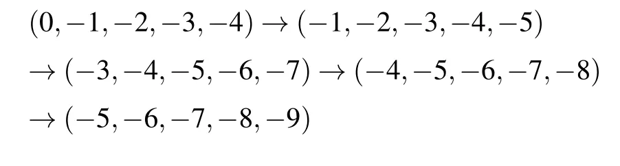
whenBvaries in[0.25,2]region. This phenomenon can be understood that the SOC induced gauge angular momentum can introduce negative canonical angular momentum, which results in a vortex with winding number (-2,-2,-2,-2,-2).Correspondingly, the polar-core vortex with phase winding(2,1,0,-1,-2)changes into the MH vortex with phase winding (0,-1,-2,-3,-4). Furthermore, giant vortices with greater phase winding number combinations are formed because of stronger IP magnetic field strength.
The magnetization ofF=2 BECs ground states can be defined asM=∫Fzdxdy, whereFzis thez-direction spin density of the five-component systems.[46]Depending on various IP magnetic field, the evolution ofMis investigated in Figs. 4(c) and 4(d). When SOC is absent, the magnetization of the ground state keeps zero for different magnetic fields which agrees well with the superposition of the different components with opposite magnetic quantum number,as shown in Fig.4(c). However,when SOC strengthκ=1,the magnetization reaches maximum atB=0.5 and decreases monotonously forB >0.5.
On the other hand, we are also interested in the misibility of the condensate when IP magnetic field is changed.We defined the degree of phase separation asnp=∫|Fz|dr,whereFzis thez-direction spin density of the five-component system.[47]For SOC strengthκ=0 in Fig. 4(e), the degree of phase separation is not influenced by IP magnetic field(np=0). This phenomenon indicates that without SOC, the condensate is totally miscible when facing IP magnetic field.However,npcan be obviously changed by IP field when SOC effect is considered,as shown in Fig.4(f).The degree of phase separationnpincreases with magnetic field whenB <0.5,while decreases with magnetic field whenB >0.5.
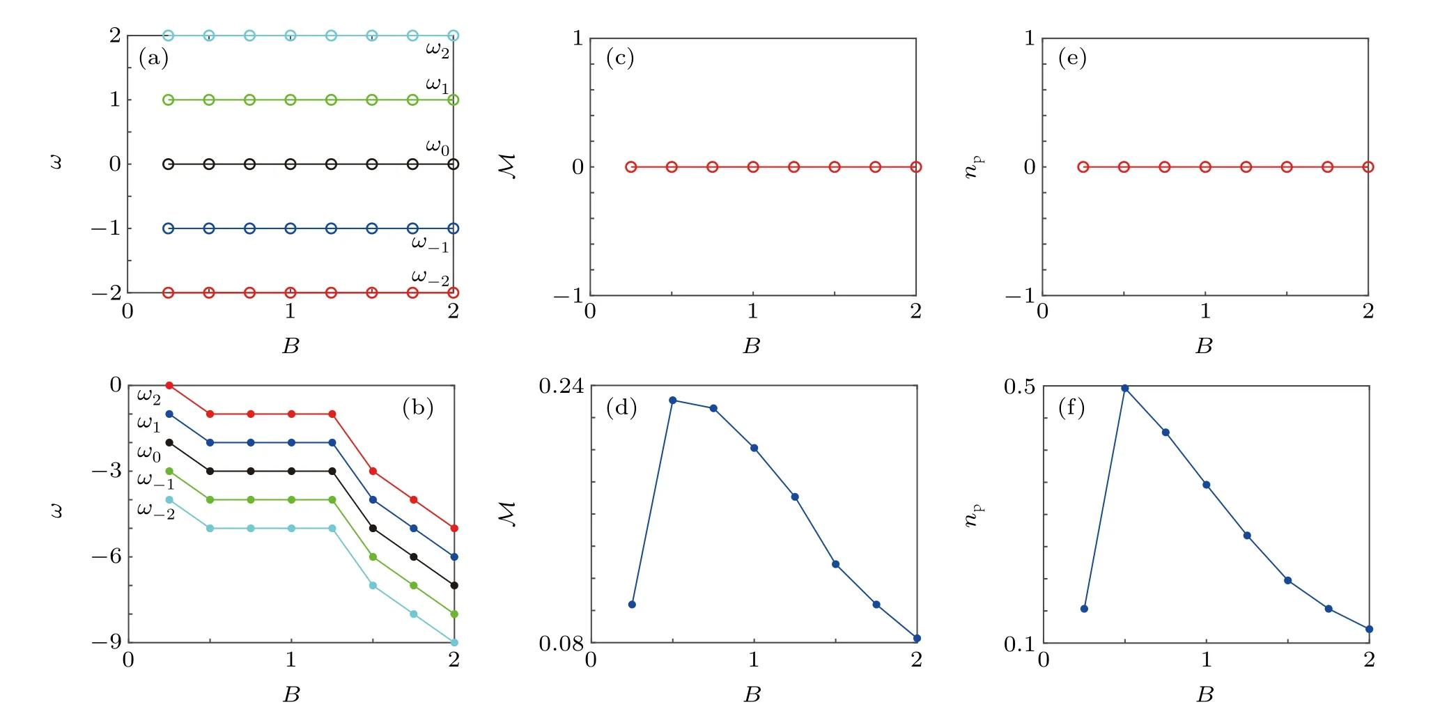
Fig.4. Phase windings of different components vary as a function of magnetic field strength B without SOC in panel(a)and with SOC κ =1 in panel(b).Magnetization M=∫Fz dxdy varies with B without SOC in panel (c) and with SOC in panel (d). Degree of phase separation np =∫|Fz|dr varies with B without SOC in panel(e)and with SOC κ =1 in panel(f). In the GP simulation, the dimensionless density-density interaction c0 =50, spin-exchange interaction c1=-5,and spin-singlet-pairing interaction c2=20. Here,the length of the harmonic trap is ξ0=
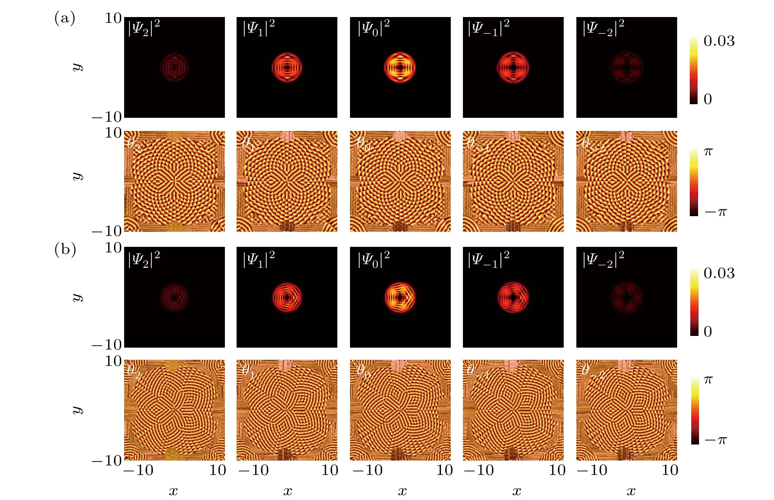
Fig. 5. Density distribution (top panel) and phase field (bottom panel) of different components as a function of SOC. The symmetrical density domains separated by vortex arrays with magnetic field strength B=1 and κ =4.5 in panel (a), κ =6 in panel (b). In the GP simulation, the dimensionless density-density interaction c0=50,spin-exchange interaction c1=-5,and spin-singlet-pairing interaction c2=20. Here,the length of the harmonic trap is ξ0=
At last, we investigate the evolution of vortex for various SOC strength when IP magnetic field is fixed (B= 1).Along with the SOC strengthκincreasing,additional vortices are generated and align radially,as depicted in Figs.5(a)-5(b)withκ=4.5,6, respectively. These vortices act as domain walls that separate the condensates into four and five symmetrical density domains. We notice that the vortex structures in different components resemble each other. It is found that the number of vortices in each array is equal and increases with SOC strengthκ. The vortices in every component share the same winding numberωl=-1, except for the central giant vortex, the internal diameter of which is bigger for stronger SOC strength.
4. Conclusion
In summary, we have investigated the ground state vortex solution under the IP magnetic field and Dresselaus-type SOC inF=2 BECs. When SOC is absent,polar-core vortex is obtained which is not influenced for stronger magnetic field.When considering SOC, MH vortex is excited with the combined effect of the magnetic field.By calculating the canonical particle current,we can identify zero canonical particle current of polar-core vortex and anticlockwise canonical particle current of MH vortex. When SOC strength is fixed,the evolution of phase winding, magnetization and degree of phase separation are thoroughly investigated. On the other hand, when magnetic field is fixed,stronger SOC may introduce additional vortices which are arranged radially acting as domain walls.
Acknowledgments
Project supported by the National Key Research and Development Program of China(Grant No.2016YFA0301500),the National Natural Science Foundation of China (Grant Nos. 61835013 and 11971067), the Strategic Priority Research Program of the Chinese Academy of Sciences (Grant Nos. XDB01020300 and XDB21030300), Beijing Natural Science Foundation, China (Grant No. 1182009), and Beijing Great Wall Talents Cultivation Program, China (Grant No.CIT&TCD20180325).

- Chinese Physics B的其它文章
- Quantum walk search algorithm for multi-objective searching with iteration auto-controlling on hypercube
- Protecting geometric quantum discord via partially collapsing measurements of two qubits in multiple bosonic reservoirs
- Beating standard quantum limit via two-axis magnetic susceptibility measurement
- Neural-mechanism-driven image block encryption algorithm incorporating a hyperchaotic system and cloud model
- Anti-function solution of uniaxial anisotropic Stoner-Wohlfarth model
- Ratchet transport of self-propelled chimeras in an asymmetric periodic structure