
In situ Observation of Li Deposition-Induced Cracking in Garnet Solid Electrolytes
2022-07-04 09:13JunZhaoYongfuTangQiushiDaiCongcongDuYinZhangDingchuanXueTianwuChenJingzhaoChenBoWangJingmingYaoNingZhaoYanshuaiLiShumanXiaXiangxinGuoStephenHarrisLiqiangZhangSulinZhangTingZhuandJianyuHuang
Energy & Environmental Materials 2022年2期
Jun Zhao, Yongfu Tang, Qiushi Dai, Congcong Du, Yin Zhang, Dingchuan Xue, Tianwu Chen,Jingzhao Chen, Bo Wang, Jingming Yao, Ning Zhao, Yanshuai Li, Shuman Xia, Xiangxin Guo,Stephen J. Harris, Liqiang Zhang*, Sulin Zhang*, Ting Zhu*, and Jianyu Huang*
1. Introduction
Solid-state batteries(SSBs)have great potential as high energy density Li battery systems for electrical vehicle and grid energy storage applications.[1–9]However, the applications of SSBs are plagued by Li penetration-induced short circuits,[10–13]mechanisms of which remain unclear.[9,12,14–20]Ceramic solid electrolytes(SEs) are often used as the ion conduction media in SSBs,because they have high mechanical strength that may block dendrite growth and thus offer better safety and longer lifetime than liquid electrolyte Li-ion batteries(LIBs).[21–24]However, Li dendrites can grow even more readily in SSBs than in liquid electrolyte LIBs. The mechanisms for Li penetrating through SEs are still under debate.It is generally thought that Li deposits and propagates preferentially along grain boundaries in SEs, causing short circuits of SSBs.[10,13,20,25,26]Cheng et al.observed a honeycomb Li structure on the fractured surface of cycled garnet SEs, and the feature size of the hexagonal web structure was similar to the grain size of the SE.[13]Based on this observation, they suggested that Li was plated along grain boundaries and proposed to increase the grain size of the SE and thus reduce its grain boundary fraction for mitigating Li penetration.[27]In situ experiments by electron beam demonstrated that defects on the garnet surface,such as surface ledges and grain boundaries,are preferable locations for Li nucleation.[25,28]Kazyak et al.observed different Li penetration morphologies with straight,branching, spalling, and diffuse types in LLZTO SEs. They found that at relatively high current densities, Li filaments propagate by a mechanical crack-opening mechanism, where the rate of propagation was proportional to the current density.[18]
Significant progress has been made in recent optical microscopy observations of dendrite growth in SEs.[18,25,29]However, the resolution of optical microscopy is limited by the wavelength of light.Also optical microscopy does not permit visualization of buried interfaces unless the SE is transparent.[12]Recently Ning et al. visualized crack propagation in Li6PS5Cl SE using in situ X-ray computed tomography (XRCT) coupled with spatially mapped X-ray diffraction.[30]They observed that cracking initiates with spallation, with conical “pothole”-like cracks forming near the surface of the plated electrode. Transverse cracks then propagated from the near-surface spallation sites across the electrolyte to the stripped electrode. Li deposition drove crack propagation and widening from the rear of the cracks until short circuit occurred. Using in situ XRCT, Hao et al.revealed the formation of thin-sheet cracks penetrating Li3PS4SE without immediate short-circuiting of the cell.[31]They found that Li only partially filled the cracks, so that the cracks near the stripped side were largely hollow and the cell could continue to operate.These studies significantly advanced our understanding of Li penetration mechanisms in SSBs. However, the spatial resolution of XRCT was limited to the micrometer scale, and grain boundaries and individual grains in SEs were not resolved. The time resolution is also not sufficiently high for resolving the dynamic cracking process near the SE surface, which is crucial for unraveling the initiation of Li deposition-induced damage in SEs. Until now, it remains unclear whether Li deposition leads to intergranular or transgranular cracking and whether Li deposition-induced cracking initiates from the surface or sub-surface of SEs. It is essential to clarify these questions toward a deeper understanding of Li penetration mechanisms in SEs,therefore providing a scientific basis for finding the effective means of mitigating Li dendrite growth in SSBs.
In this work, we design a novel mesoscale electrochemical device in a focused ion beam-scanning electron microscopy (FIBSEM) system, which enables real-time observations of Li deposition and cracking in LLZTO SEs at nanometer resolution. Meanwhile, we can verify the internal structural changes of LLZTO SEs by FIB-SEM tomography.[32,33]We show that Li deposition induces predominantly transgranular cracking rather than intergranular cracking in ceramic LLZTO. Chunks of LLZTO are lifted out by the formation of near-surface bowl-shaped cracks, which resemble those from “hydraulic fracture” caused by highly pressurized fluids within the cracks[34,35]and thus suggest the Li deposition-induced internal pressure as the major driving force of crack initiation and propagation. Our in situ observations also reveal detailed dynamic interplay between Li deposition and crack propagation and multiplication. These results advance our understanding of Li penetration mechanisms in SEs.
2. Results and Discussion
Our experiments were conducted in an FIB-SEM system, where a two-terminal electrochemical device was constructed to enable in situ testing of a mesoscale battery. LLZTO with the cubic crystal structure(Figure S1, Supporting Information) was synthesized via hot pressing at a pressure of 20 MPa and a temperature of 1150 °C for 1 h under Ar atmosphere. An LLZTO disk with a diameter of 12 mm and thickness of 1 mm was placed on a Li metal electrode supported by an SEM sample stub, which was connected to one terminal of an external power supply (Figure 1a). On the top surface of the LLZTO disk,a Pt electrode pad of 10 µm × 10 µm was deposited using electron beam. A W tip was manipulated to contact the Pt electrode, and it was connected to the other terminal of the potentiostat, thus completing the mesoscale battery setup. This mesoscale battery was used for in situ observation of Li deposition and cracking in LLZTO. Similar results were obtained when the Li metal electrode was replaced by a layer of InGaAg liquid metal.
As a negative potential was applied to the Pt electrode, a fine-line crack with a closed-loop contour appeared on the top surface of the LLZTO disk (Figure 1b–d; Figure S2, Supporting Information). With the passage of time, Li metal emerged along the crack line and was then extruded out at the LLZTO surface (Figure 1b; Figure S2, Supporting Information). The crack line was widened as more Li extruded until a Li ring was formed on the top surface of the LLZTO disk (Figure 1b-d; Figure S2, Supporting Information).Before battery testing, the grain boundary contours on the LLZTO surface were made visible (Experimental Section), permitting the identification of individual grains (Figure 1b, c; Figure S2, Supporting Information). Interestingly, we found that the cracks were predominantly transgranular (through grains) rather than intergranular (along grain boundaries) (Figure 1c; Figure S2, Supporting Information). Moreover, the entire Li ring was lifted up the LLZTO surface (Figure 1b-d; Figure S2, Movie S1, Supporting Information). To reveal how deep the surface crack ran, a trench perpendicular to the LLZTO top surface was milled out by FIB(Figure 1d, e). To our surprise, a "bowl-shaped" crack was formed underneath the Pt electrode (Figure 1d, e), and such kind of three-dimensional (3D), near-surface crack geometry was highly reproducible. Apparently, the "bowl" was spalled off the LLZTO matrix, as it was entirely lifted up from the LLZTO surface presumably by deposited Li.
To reveal the dynamic formation of the bowl-shaped crack, we pre-milled a trench near the Pt electrode to expose one side surface of the trench (Figure 1f, g). Upon applying a negative potential to the Pt electrode, Li dendrites initially grew at the Pt electrode pad on the LLZTO surface (Figure 1h, i). With increasing potential, a few crack segments emerged and extended on the exposed side surface of the trench (Figure 1g; Movie S2, Supporting Information). By monitoring the evolution of the 3D morphology of two bowl-shaped cracks involved (Figure 1f), we understood the growth processes of these crack segments as follows. At 68 s (Figure 1j), the tip of one bowl-shaped crack (outlined by a blue dotted line) extended into the exposed side surface of the trench and continued to propagate toward its upper left;meanwhile, a branch of another bowl-shaped crack (outlined by a yellow dotted line) emerged near the LLZTO surface. At 212 s(Figure 1k), the first bowl-shaped crack grew longer toward its upper left to merge with the second bowl-shaped crack (Movie S2, Supporting Information). These in situ observations provide evidence of the growth of the bowl-shaped crack from the interior to the top surface of LLZTO. During this process, the crack contour lines on the top surface of the LLZTO disk were widened due to filling of Li metal between the crack flanks (Figure 1j), eventually forming two overlapped Li rings on the LLZTO surface (Figure 1k). Figure S3, Supporting Information provides one more example of the formation of a bowl-shaped crack underneath the Pt electrode. It appears that only a segment of the bowl-shaped crack (Figure S3b, c, left, yellow dotted lines, Supporting Information) reached the LLZTO surface. Once the crack reached the surface, Li was immediately extruded out of the surface from the crack (Figure S3b–d, Supporting Information). The cross-sectional view confirms that only the left segment of the bowl crack reached the surface (Figure S3e, f, Supporting Information). Voids filled with Li near the crack were present on the exposed side surface of LLZTO (Figure S3e, f, Supporting Information).
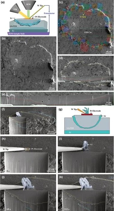
Figure 1. In situ observation of Li deposition and cracking in SEs by a mesoscale FIB-SEM-based SSB,showing two sets of time sequence images in (a-e)and (f-k) for the formation of bowl-shaped cracks followed by Li filling in cracks. a) Schematic of the in situ battery testing, resulting in the formation of a bowl-shaped crack. A Pt electrode was deposited on the top surface of the LLZTO SE. Li or liquid GaInAg metal was used as the counter electrode. b, c) SEM images showing the formation of a bowl-shaped crack in the LLZTO SE. c) is the same as b), except that the colored grains around the bowl-shaped crack line on the LLZTO surface are sketched and overlaid on the real grains, showing the crack path through grain interiors. d) A cross-sectional view of the bowl-shaped crack, where the yellow and red dotted lines outline the bowl-shaped crack on the top surface and cross section, respectively. e)Magnified view of the bowl-shaped crack on the cross section from FIB milling, corresponding to the region boxed by green dotted lines in (d). f–k) In situ observation of the dynamic formation of a bowl-shaped crack and Li filling. f) A full view of the bowl-shaped crack, showing the crack contour on both the top surface and cross section. Li dendrites formed at the Pt electrode pad before the occurrence of LLZTO cracking. g) Schematic of the Li dendrites, bowl-shaped crack, and filled Li in the crack. h) LLZTO was milled by FIB to expose its side surface. h–k) Time-lapse images showing the formation of a bowl-shaped crack. A dendrite appeared near the Pt electrode (i) and then grew (j);the formation of two bowl-shaped cracks is shown in (j, k). The growth of dendrites appeared to cease once the bowl-shaped crack emerged by comparing(j) and (k).
Li filling of the cracks was observed in real time (Figure 2; Movie S3, Supporting Information). Figure 2a shows an FIB-milled cross section with two crossing crack segments (denoted as crack 1 and 2). The full profile of the bowl-shaped crack is shown in Figure S4,Supporting Information. With the passage of time, crack 4 extended into the cross section, propagated from the lower right toward the upper left, and merged with crack 1. Subsequently, crack 4 widened(Figure 2b–d, g–n; Movie S3, Supporting Information) as Li was filled in the space between the crack flanks. The Li filling front is marked by a moving green arrowhead in Figure 2i–n. Since crack 1 and 4 were connected, the widening of crack 4 by Li filling also led to the widening of crack 1. As a result, a small crack formed near crack 1 at the upper left corner of the cross section, and this newly formed crack is indicated by an arrowhead and marked as crack 3 in Figure 2b. Interestingly, as crack 1 and 4 were connected and widened (Figure 2g–n), the lower right segment of crack 1 was closed (marked by a down pointed arrowhead in Figure 2n), likely due to compression caused by the widening of crack 4. The above in situ observations demonstrate that the filled Li between crack flanks can flow and, more importantly, produce sufficiently high internal pressure to cause the formation, widening, and closing of cracks.Upon a reverse potential, crack 1 was closed (Figure 2e, o; Figure S5, Supporting Information). Dendrites that break off will lost contact with the lithium metal anodes and become dead lithium as shown in Figure S6, Supporting Information resulting in the cracks being unable to be healed completely.
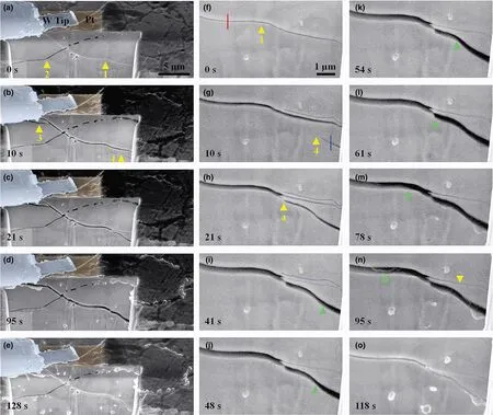
Figure 2. In situ observation of the dynamic interplay between crack opening and Li filling in the bowl-shaped crack. a–e) Sequential SEM images showing the dynamic processes of Li filling in a segment of the bowl-shaped crack. f–o) High-magnification SEM images showing Li filling and extracting from the bowl-shaped crack. Note that the crack was widened when Li was filled in between the crack flanks (a–d, f–n), and the crack was closed when Li was extracted (e, o). "1"-"4" mark four different cracks. A green arrowhead indicates the Li moving front in (i–n).
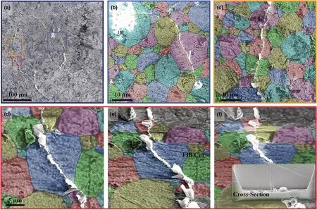
Figure 3. SEM images showing Li transpassing LLZTO grains. a–d) Plan view of cracks transpassing grain interiors. a) A full view of the bowl-shaped crack line (outlined by yellow dotted lines) on the top surface of LLZTO. Blue dotted lines outline segments of another bowl-shaped crack. b–f) Magnified view of crack transpassing grain interiors. The false color outlines grains, showing cracks transpassing grain interiors.
By SEM imaging at higher magnification, Li deposition along transgranular cracks became clearly visible (Figure 3). Figure 3a shows the top view of the LLZTO surface where a bowl-shaped crack emerges as a closed-loop crack line (traced by yellow dotted lines) that intersects with another emerging crack line (traced by blue dotted lines) from a different bowl-shaped crack. High-magnification images of the boxed regions in Figure 3a show clearly the surface cracks crossing the interior of a series of grains (Figure 3b–f). The FIB-milled cross section reveals that the surface transgranular crack penetrated into the interior of the LLZTO disk (Figure 3f). The original image of Figure 3 is shown in Figure S7,Supporting Information.
To investigate the transgranular fracture induced by Li deposition,we show that cracks can nucleate and propagate in single-crystal LLZTO grains (Figure 4 and Movies S4, S5, Supporting Information). A single-crystal grain was sliced by FIB milling so that a flat side surface was exposed (Figure 4a). Then, the W tip was manipulated to contact this side surface(Figure 4a).When a negative potential was applied to the W tip,a Li dendrite initially grew out under the W tip(Figure 4b).With continued dendrite growth,a slanted crack emerged in the center of the particle (Figure 4b–d, yellow dotted lines), and then, the crack propagated toward the upper-right direction until the grain broke into two parts (Figure 4b–d,Movie S4,Supporting Information). Consecutive FIB slicing along the side surface indicates that the crack crossed through the entire grain (Figure 4e–i, Movie S5, Supporting Information).
We further show that a crack can cross through two neighboring grains continuously in a multi-grained LLZTO particle (Figure 5a–i).The particle comprised at least three grains with grain boundaries and cavities(Figure 5a–i).We made a Pt electrode pad on top of the particle(Figure 5a).Upon applying a negative potential to the Pt electrode,three Li dendrites appeared at the edge of the contact pad(indicated by three green arrowheads in Figure 5f). At 283 s, another slim dendrite emerged accompanying the formation of a microcrack in grain 1(Figure 5c,g).The crack was neither stopped nor deflected by the grain boundaries; instead, it crossed directly into grain 2 and then propagated downward through grain 2 (Figure 5c–e, g–i, Movie S6, Supporting Information). We milled the particle to expose its side surface, which showed that the crack ran through the entire particle, breaking the particle into two parts (Figure 5j–l;Movie S7,Supporting Information).

Figure 4. Time-lapse SEM images showing crack nucleation and propagation in a single LLZTO grain. a) The initial LLZTO grain with side surface being exposed. b–d) A dendrite and a slanted crack emerged from the LLZTO grain (traced by yellow dotted lines). e–i) Consecutive FIB slicing of the grain showing the crack running from the top to the bottom section of the entire grain, breaking the grain into two pieces. i) Schematic of the slicing process.
Based on the above in situ observations, we envision the following mechanisms of Li deposition-induced nucleation and growth of bowlshaped cracks (Figure 6a–f). As a sufficiently large negative potential was applied to the Pt electrode, significant Li deposition took place underneath the Pt electrode pad,presumably at favored internal defects such as voids or grain boundaries (Figure 6a, b). These voids may include intragranular voids,not just those between grains.We used FIB to slice single-crystal LLZTO grains and found that almost all of them contain microscale voids (Figure S8; Movie S8, Supporting Information). Electrons needed for the reduction of Li ions are likely available due to the small,but finite electrical conductivity of LLZTO.[14]Li deposition could be enhanced by the elevated electric field near the Pt electrode that promoted electron flow.Li deposition was self-amplified due to increased electronic conductivity at these Li deposition sites. Under the mechanical confinement of the surrounding LLZTO, continued Li deposition leads to the buildup of large internal pressure,triggering the nucleation of an internal crack through the expansion of a Li-filled defect.
The observed formation of bowl-shaped cracks provides crucial insights into the dynamic interplay of Li deposition and crack growth in SEs. The characteristic bowl-shaped cracks have been previously reported in the study of hydraulic fracture in geomaterials and civil engineering applications.[34,35]Hydraulic fracture is usually caused by high fluid pressure on the surface of internal cracks in a bulk material.During hydraulic fracture, a sub-surface crack parallel to the free surface is loaded by a pressurized fluid within the crack, and the moving fluid front between the crack flanks usually falls behind the running crack tip,such that crack propagation mainly involves mechanical fracture at the crack front. Due to surface attraction, a sub-surface crack often propagates by curving to the free surface,forming a characteristic bowl-shaped crack.[34,35]The striking formation of the bowl-shaped cracks during LLZTO fracture suggests a similar “hydraulic fracture”mechanism of crack growth driven by Li deposition. Specifically, we considered a small penny-shaped crack that has nucleated due to Li deposition-induced pressure inside an internal defect in LLZTO,as discussed earlier. Since LLZTO is brittle, a crack, once nucleated, propagates fast,leaving the deposited Li behind. Crack extension releases the deposition-induced pressure, resulting in the arrest of the crack front.The filled Li metal in the crack provides an electron conduction path to facilitate further Li deposition. At a Li deposition site along filled Li,the increasing Li volume causes an increase of local pressure acting on the crack surface. The local pressures may be possibly generated at different Li deposition sites along filled Li,and they collectively provide a driving force of crack extension. These pressures also act on filled Li and collectively provide a driving force of Li flow in between the crack flanks, as revealed in Figure 2. To assess the feasibility of flow and pressure buildup of filled Li within the internal cracks of LLZTO, we note that the melting point of Li metal (Tm) is ˜180.5 °C, and room temperature corresponds to a homologous temperature of 0.66Tm,suggesting that filled Li could flow by creeping.[9,36]The yield stress of viscoplastic Li could be considerably high within the small gap between the crack flanks,ranging from sub-microns to microns.[37–39]Meanwhile, Li deposition-induced stress can reach GPa level as measured by in situ environmental transmission electron microscope(ETEM) in our recent work.[40]Hence, the filled Li could act similarly like a pressurized fluid within the crack during hydraulic fracture, so as to generate sufficiently high internal pressure for driving the growth of a sub-surface bowl-shaped crack. Finally, we note that Ni et al.recently reported the formation of similar bowl-shaped cracks at the edges of large-area electrodes on the surface of several SEs, referred toas conical “pothole”-like cracks.[30]Hence, bowl-shaped cracking near the surface represents a common mechanism of Li penetration-induced SE fracture.

3. Conclusion
In summary,the above in situ experimental results provide important insights into the mitigation of Li penetration inside SEs. Care must be taken to both the microstructures and properties of SEs as well as the electrode geometry for suppressing near-surface cracking, which plays a critical role in the initiation of Li penetration through SEs. In fact, recent experiments indicate that long cracks penetrating SEs usually emanate from near-surface cracks.[30,31]To alleviate near-surface cracking, it is essential to minimize the processing-induced defects and increase the fracture strength to resist against both intergranular and transgranular crack propagation in SEs. Moreover, careful design of the electrode geometry may help reduce electrically induced stresses that could affect the initial formation of sub-surface cracks near the electrode edges and thus have a profound impact on Li penetration through SE layers. As Li deposition and penetration can be closely related to electron leakage to SEs,it is important to block the leakage through innovative material and interface designs.
4. Experimental Section
The experiment was performed in an FIB-SEM system (Helios G4 CX; Thermo Fisher Scientific). In the mesoscale battery setup, a W tip was connected to a Pt electrode deposited on top of the LLZTO surface, and this W tip was also connected to the negative terminal of a potentiostat(2612B Source Meter;Keithley).The garnet-type SE pellets were placed on either Li or liquid InGaAg metals,which were supported by an SEM sample stub connected to the other terminal of a potentiostat. Both garnet-type LLZTO pellets (diameter of 12 mm and thickness of 1 mm)and LLZTO particles(diameter of 2–20 µm)were purchased from Jining CreaTech New Energy Technology Co., Ltd. These garnet pellets and particles were synthesized via conventional solid-state reaction reported previously.Liquid metal InGaAg was purchased from Aladdin.
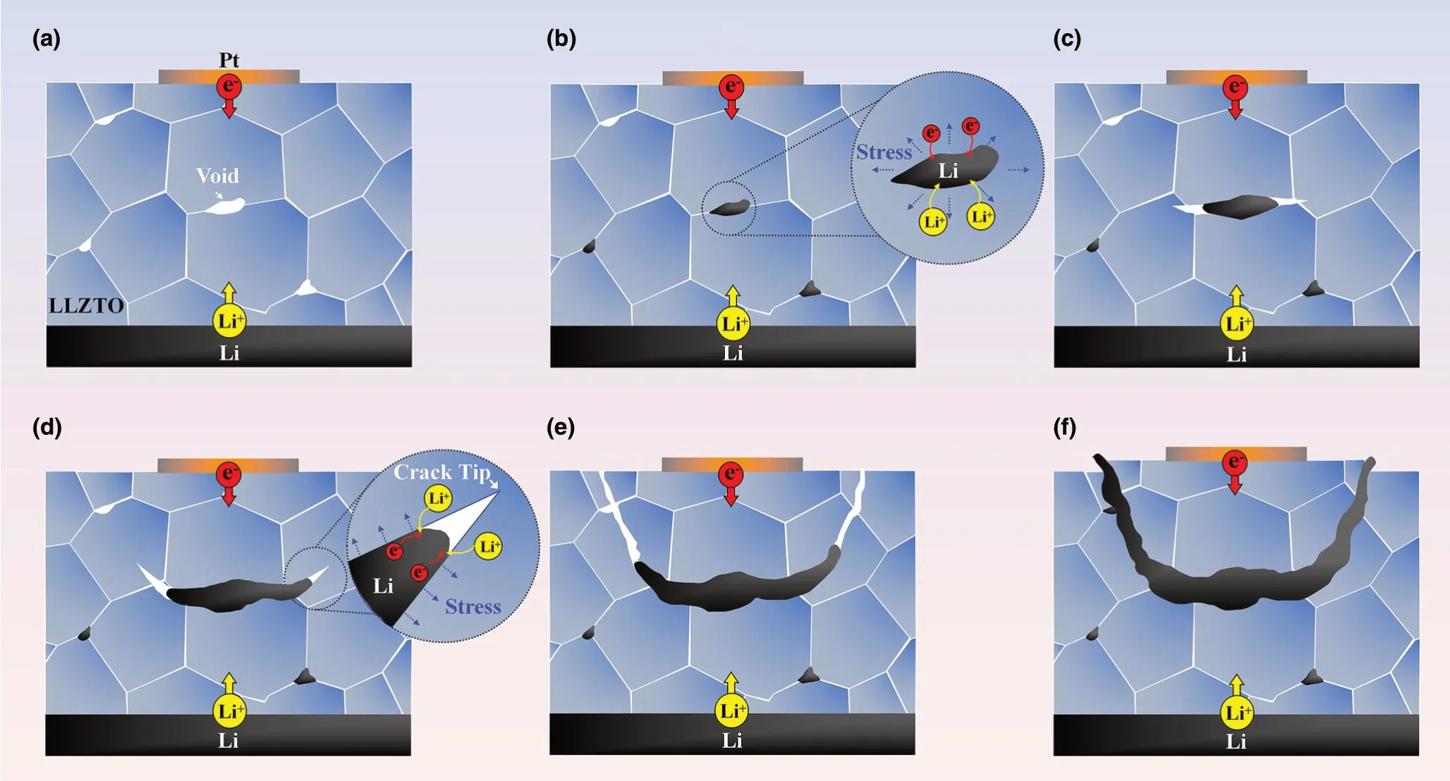
Figure 6. Schematic illustration of the formation mechanism of the bowl-shaped crack. a–c) Li deposition initiates at internal defects such as voids (a, b),generating high pressure in Li-filled defects, causing crack nucleation and propagation and then continued Li filling in between the crack flanks behind the running crack front (b-c). The filled Li is constrained by the crack flanks, producing wedging stresses to drive the crack propagation (d). Due to surface attraction, the running crack curves toward the free surface, resulting in a bowl-shaped crack (d, e), and a chunk of LLZTO spalled off and was lifted up by filled Li in the bowl-shaped crack (f).
To clearly observe grain boundaries on the top surface of LLZTO,the polished LLZTO pellets were heat-treated in the Ar atmosphere at 900 °C.The LLZTO pellet was rubbed on the molten Li under 250 °C to construct the Li/LLZTO interface in the glove box, and then, the Li anode was attached to the SEM sample stub assisted by a vacuum transfer box. On the top surface of the LLZTO disk, a Pt electrode pad was deposited using ion beam-induced deposition at 30 kV, 80 pA.The W tip of the easy-lift was manipulated to contact the Pt electrode. To investigate the crack nucleation and propagation in an individual LLZTO grain during Li deposition, LLZTO particles composed of single-grain or multi-grain LLZTO were dispersed on the Li metal which was attached to the SEM sample stub. To improve the electric contact between the Li metal and LLZTO grains, the LLZTO particles were pressed into the Li metal using the W tip before in situ voltagebiasing experiments.
Acknowledgements
J.Z., Q.D., and Y.T. contributed equally to this work. This work was financially supported by the National Natural Science Foundation of China (Nos.52022088, 51971245, 51772262, 21406191, U20A20336, 21935009, 51771222,52002197), Beijing Natural Science Foundation (2202046), Fok Ying-Tong Education Foundation of China (No. 171064), Natural Science Foundation of Hebei Province (No. F2021203097, B2020203037, B2018203297), and Hunan Innovation Team (2018RS3091). Part of this work was supported by the Assistant Secretary for Energy, Vehicles Technology Office, of the U.S. Department of Energy under Contract (No. DEAC02-05CH11231). L.Z., Y.T., and J.H. conceived and designed the project. J.Z., Q.D., B.W., J.C., N.Z., Y.L., Y.Z., D.X., T.C., S.X., and X.G. fabricated the samples. J.Z., C.D., and J.Y. carried out the in situ experiments. L.Z., Y.T., T.Z., and J.H. supervised the experiments. S.J.H., T.Z., S.Z.,and J.H. co-wrote the paper. All the authors discussed the results and commented on the manuscript.
Conflict of Interest
The authors declare no conflict of interest.
Supporting Information
Supporting Informationis available from the Wiley Online Library or from the author.
Keywords
cracking, garnet solid electrolyte, in situ observation, Li deposition
Received: July 9, 2021
Revised: August 7, 2021
Published online: August 12, 2021
[1] W. Xu, J. Wang, F. Ding, X. Chen, E. Nasybulin, Y. Zhang, J.-G. Zhang,Energy Environ. Sci. 2014, 7, 513.
[2] T. Krauskopf, H. Hartmann, W. G. Zeier, J. Janek, A. C. S. Appl, Mater.Interfaces 2019, 11, 14463.
[3] D. Lin, Y. Liu, Y. Cui, Nat. Nanotechnol. 2017, 12, 194.
[4] Y. Guo, H. Li, T. Zhai, Adv. Mater. 2017, 29, 1700007.
[5] X. Wang, W. Zeng, L. Hong, W. Xu, H. Yang, F. Wang, H. Duan, M.Tang, H. Jiang, Nat. Energy 2018, 3, 227.
[6] Z. Zou, Y. Li, Z. Lu, D. Wang, Y. Cui, B. Guo, Y. Li, X. Liang, J. Feng, H. Li,C.-W. Nan, M. Armand, L. Chen, K. Xu, S. Shi, Chem. Rev. 2020, 120, 4169.
[7] M. Winter, B. Barnett, K. Xu, Chem. Rev. 2018, 118, 11433.
[8] H. Huo, J. Luo, V. Thangadurai, X. Guo, C.-W. Nan, X. Sun, ACS Energy Lett. 2020, 5, 252.
[9] Y. Tang, L. Zhang, J. Chen, H. Sun, T. Yang, Q. Liu, Q. Huang, T. Zhu, J.Huang, Energy Environ. Sci. 2021, 14, 602.
[10] Y. Ren, Y. Shen, Y. Lin, C.-W. Nan, Electrochem. Commun. 2015, 57,27.
[11] Y. Suzuki, K. Kami, K. Watanabe, A. Watanabe, N. Saito, T. Ohnishi, K.Takada, R. Sudo, N. Imanishi, Solid State Ionics 2015, 278, 172.
[12] L. Porz, T. Swamy, B. W. Sheldon, D. Rettenwander, T. Fr¨omling, H. L.Thaman, S. Berendts, R. Uecker, W. C. Carter, Y.-M. Chiang, Adv. Energy Mater. 2017, 7, 1701003.
[13] E. J. Cheng, A. Sharafi, J. Sakamoto, Electrochim. Acta 2017, 223, 85.
[14] F. Han, A. S. Westover, J. Yue, X. Fan, F. Wang, M. Chi, D. N. Leonard,N. J. Dudney, H. Wang, C. Wang, Nat. Energy 2019, 4, 187.
[15] S. S. Shishvan, N. A. Fleck, R. M. McMeeking, V. S. Deshpande, Acta Mater. 2020, 196, 444.
[16] S. S. Shishvan, N. A. Fleck, R. M. McMeeking, V. S. Deshpande, J. Power Sources 2020, 456, 227989.
[17] Y. Qi, C. Ban, S. J. Harris, Joule 2020, 4, 2599.
[18] E. Kazyak, R. Garcia-Mendez, W. S. LePage, A. Sharafi, A. L. Davis, A. J.Sanchez, K.-H. Chen, C. Haslam, J. Sakamoto, N. P. Dasgupta, Matter 2020, 2, 1025.
[19] K. Kerman, A. Luntz, V. Viswanathan, Y.-M. Chiang, Z. Chen, J. Electrochem. Soc. 2017, 164, A1731.
[20] T.Swamy,R.Park, B. W. Sheldon,D.Rettenwander,L.Porz, S. Berendts, R.Uecker,W.C.Carter,Y.-M.Chiang,J.Electrochem.Soc.2018,165,A3648.
[21] C. Monroe, J. Newman, J. Electrochem. Soc. 2004, 151, A880.
[22] M. Charles, S. N. John, J. Electrochem. Soc. 2005, 152, A369.
[23] J. Wen, Y. Huang, J. Duan, Y. Wu, W. Luo, L. Zhou, C. Hu, L. Huang, X.Zheng, W. Yang, Z. Wen, Y. Huang, ACS Nano 2019, 13, 14549.
[24] W. Wu, J. Duan, J. Wen, Y. Chen, X. Liu, L. Huang, Z. Wang, S. Deng, Y.Huang, W. Luo, Sci. China Chem. 2020, 63, 1483.
[25] T. Krauskopf, R. Dippel, H. Hartmann, K. Peppler, B. Mogwitz, F. H.Richter, W. G. Zeier, J. Janek, Joule 2019, 3, 2030.
[26] R. Sudo, Y. Nakata, K. Ishiguro, M. Matsui, A. Hirano, Y. Takeda, O.Yamamoto, N. Imanishi, Solid State Ionics 2014, 262, 151.
[27] A. Sharafi, C. G. Haslam, R. D. Kerns, J. Wolfenstine, J. Sakamoto, J.Mater. Chem. A 2017, 5, 21491.
[28] X. Xie, J. Xing, D. Hu, H. Gu, C. Chen, X. Guo, A. C. S. Appl, Mater.Interfaces 2018, 10, 5978.
[29] A. J. Sanchez, E. Kazyak, Y. Chen, K.-H. Chen, E. R. Pattison, N. P. Dasgupta, ACS Energy Lett. 2020, 5, 994.
[30] Z. Ning, D. S. Jolly, G. Li, R. De Meyere, S. D. Pu, Y. Chen, J. Kasemchainan, J. Ihli, C. Gong, B. Liu, D. L. R. Melvin, A. Bonnin, O. Magdysyuk, P. Adamson, G. O. Hartley, C. W. Monroe, T. J. Marrow, P. G.Bruce, Nat. Mater. 2021, 20, 1.
[31] S. Hao, S. R. Daemi, T. M. M. Heenan, W. Du, C. Tan, M. Storm, C. Rau,D. J. L. Brett, P. R. Shearing, Nano Energy 2021, 82, 105744.
[32] K.Dong,Y.Xu,J.Tan,M.Osenberg,F.Sun,Z.Kochovski,D.T.Pham,S.Mei,A.Hilger,E.Ryan,Y.Lu,J.Banhart,I.Manke,ACS Energy Lett.2021,6,1719.
[33] X. Yao, T. ˘Samo˘ril, J. Dluho˘s, J. F. Watts, Z. Du, B. Song, S. R. P. Silva, T.Sui, Y. Zhao, Energy Environ. Mater. https://doi.org/10.1002/eem2.12221
[34] E. Gordeliy, E. Detournay, J. A. L. Napier, 44th US Rock Mechanics Symposium - 5th US/Canada Rock Mechanics Symposium 2010.
[35] E. Gordeliy, R. Piccinin, J. A. L. Napier, E. Detournay, Eng. Fract. Mech.2013, 102, 348.
[36] Y. Chen, Z. Wang, X. Li, X. Yao, C. Wang, Y. Li, W. Xue, D. Yu, S. Y.Kim, F. Yang, A. Kushima, G. Zhang, H. Huang, N. Wu, Y.-W. Mai, J. B.Goodenough, J. Li, Nature 2020, 578, 251.
[37] C. Xu, Z. Ahmad, A. Aryanfar, V. Viswanathan, J. R. Greer, Proc. Natl Acad. Sci. 2017, 114, 57.
[38] L. Zhang, T. Yang, C. Du, Q. Liu, Y. Tang, J. Zhao, B. Wang, T. Chen, Y.Sun, P. Jia, H. Li, L. Geng, J. Chen, H. Ye, Z. Wang, Y. Li, H. Sun, X. Li, Q.Dai, Y. Tang, Q. Peng, T. Shen, S. Zhang, T. Zhu, J. Huang, Nat. Nanotechnol. 2020, 15, 94.
[39] Y. He, X. Ren, Y. Xu, M. H. Engelhard, X. Li, J. Xiao, J. Liu, J.-G. Zhang,W. Xu, C. Wang, Nat. Nanotechnol. 2019, 14, 1042.
[40] J. Chen, C. Zhao, D. Xue, L. Zhang, T. Yang, C. Du, X. Zhang, R. Fang, B.Guo, H. Ye, H. Li, Q. Dai, J. Zhao, Y. Li, S. Harris, Y. Tang, F. Ding, S.Zhang, J. Huang, Nano Lett. https://doi.org/10.1021/acs.nanolett.1c01910
 Energy & Environmental Materials2022年2期
- Energy & Environmental Materials的其它文章
- Progress of Pb-Sn Mixed Perovskites for Photovoltaics:A Review
- Development Strategies in Transition Metal Borides for Electrochemical Water Splitting
- Polymer-/Ceramic-based Dielectric Composites for Energy Storage and Conversion
- Controllable Construction of Bifunctional CoxP@N,P-Doped Carbon Electrocatalysts for Rechargeable Zinc–Air Batteries
- Unveiling the Underlying Mechanism of Transition Metal Atoms Anchored Square Tetracyanoquinodimethane Monolayers as Electrocatalysts for N2 Fixation
- Rational Design of High-Performance Bilayer Solar Evaporator by Using Waste Polyester-Derived Porous Carbon-Coated Wood