
Multidimensional Hybrid Architecture Encapsulating Cobalt Oxide Nanoparticles into Carbon Nanotube Branched Nitrogen-Doped Reduced Graphene Oxide Networks for Lithium–Sulfur Batteries
2022-07-04 09:13JeongSeokYeonYoungHunKoTaeHoParkHyunyoungParkJongsoonKimandHoSeokPark
Energy & Environmental Materials 2022年2期
Jeong Seok Yeon, Young Hun Ko, Tae Ho Park, Hyunyoung Park, Jongsoon Kim, and Ho Seok Park*
1. Introduction
The development of a variety of portable devices, electric vehicles, and other application markets is increasing the demand for batteries,and therefore,there is a constant need for highenergy-density storage devices.[1]Conventional lithium-ion batteries (LIBs), based on an intercalation mechanism, are losing appeal due to their low energy densities. Lithium–sulfur batteries (LSBs) are emerging as the next-generation battery, owing to an outstanding theoretical energy density (2600 Wh kg−1),which is six times that of current LIB systems.[2]The affordable cost of high-capacity sulfur (S,1675 mAh g−1)and its abundance on earth are added benefits of LSB technology.[3]However,several limitations need to be resolved in order for the technology to become viable for practical applications: 1) The intrinsically inferior electrical conductivity of S (5 × 10⁻³⁰S cm−1at 25 °C) and its discharged products (Li2S2and Li2S);[4]2) Large volumetric expansion(~80%) which is attributed to density differences between S (2.03 g cm−3) and Li2S(1.67 g cm−3);[5]and 3) The shuttle effect which is caused by the dissolution of the intermediate polysulfide into the electrolyte.[6]These limitations result in significantly diminished performance that is associated with low utilization of active S materials,self-discharge,rapid capacity fading,degradation of electrode,and poor coulombic efficiency.
In order to overcome the limitations of S cathodes, various hosting materials have been investigated as frameworks for electrodes. For instance,several carbon-based conductive host matrices,including hierarchical carbon,[7]carbon spheres,[8]carbon nanotubes (CNTs),[9]and reduced graphene oxide (rGO),[10]have been employed to physically trap the polysulfide and encapsulate active S and to improve the electrical conductivity of S cathodes for the efficient utilization of S.[11]However,non-polar carbon hosting materials are not effective in mitigating the shuttle effect due to poor intermolecular interactions.[12]In order to strengthen the specific interaction between carbon and polysulfides,heteroatoms, such as N,[13]S,[14]B,[15]and O,[16]have been incorporated onto the surface of conductive carbons.Recently,transition metal oxides(TMOs)have been developed as promising hosting material candidates due to their strong surface polarity, effectively reducing diffusion of lithium polysulfides (LiPSs) into the electrolyte through the strong chemical interaction with the LiPSs, or through an electrocatalytic effect that promotes LiPS redox kinetics.[17−19]However, the intrinsically insulating features, high-mass density, and brittleness of TMOs hinder the role of the hosting material, diminishing the energy density and cycle life of LSB cells.[20]
The multidimensional hierarchical architecture achievable with TMOs and carbon nanomaterials is regarded as one of the promising chemical strategy for synergistic effect of the different structural and compositional characteristics of respective nanostructured materials.[21]The integration of one-dimensional(1D)structures onto a two-dimensional (2D) substrate is an example of hierarchical complex structures developed for an electrode used in high-performance energy storage devices. For instance, TMOs in a form of the 1D structures including nanorods,nanowires,and nanotubes were integrated with 2D graphene to fabricate three-dimensional(3D)hierarchical architectures.[22]Moreover, 1D CNTs have also been not only used as a conductive network,but also provided electronic pathways with low charge transfer resistance and delocalizing stress concentration during volume expansion and contraction.[23]Both 1D CNT and 2D graphene could be assembled into multidimensional internetworked architectures in order to achieve the advantages characteristic of 3D hierarchical structures, such as a large accessible area, fast ion diffusion, percolated electron transport,and the buffering effect.[24]Although polar or active TMOs have been incorporated onto the surface of 3D hierarchical CNT or graphene networks, they are not stable due to surface exposure and interparticle aggregation.[25]Moreover, TMO nanoparticles (NPs) encapsulated within the tubes of multidimensionally architectured 1D CNT/2D rGO hybrids have yet to be explored in terms of cathode hosting in LSBs.
In this study, we developed a multidimensional hybrid architecture encapsulating Co3O4NPs into a CNT/N-doped rGO (Co@CNT/nG),for use in LSBs,to host active S,prevent LiPS dissolution,and accelerate the conversion redox kinetics. The unique hierarchical design provides percolated electron/ion conducting pathways formed by the interconnected CNT networks and stabilizing Co3O4NPs confined within the tubes. In particular, Co3O4NPs catalyze the growth of CNT branches forming the multidimensional complex architecture and promote the redox kinetics for high S utilization. Consequently, a Co@CNT/nG-70S-based LSB cell delivers a high discharge capacity,1193.1 mAh g−1at 0.1 C, and low-capacity decay rates of 0.037 and 0.030% per cycle for 700 cycles at 2 and 5 C,respectively.Furthermore,the areal capacity of Co@CNT/nG-70S-based LSB cell with a high loading of 6.5 mg cm−2was 5.62 mAh cm−2, which confirms the potential of Co@CNT/nG as a high-performance S host electrode for LSBs.
2. Results and Discussion
The synthesis procedures of the Co@CNT/nG-70S are illustrated in Figure 1a.A facile one-pot synthesis was employed to prepare Co3O4NPs encapsulated in hierarchically structured N-doped rGO interconnected with grown CNT branches (denoted as Co@CNT/nG) using a cobalt precursor (Co(NO3)2∙6H2O), dicyandiamide (DCDA), and graphene oxide (GO). In briefly,GO solution was mixed with Co(NO3)2∙6H2O and DCDA to obtain homogeneous aqueous dispersion, followed by freeze-drying for 3 days to obtain mixture powder (Figure 1a-A). The dried powder was annealed under Ar atmosphere to obtain Co@CNT/nG in two steps pyrolysis process. In the first pyrolysis step at 400 °C(Figure 1a-B), DCDA was decomposed into layered graphitic carbon nitride(g-C3N4).As shown in Figure S1,the TGA curve of DCDA was observed multi-step weight loss steps,which gradually condensed to g-C3N4after 400 °C and then decomposed completely above 710 °C.The existence of g-C3N4was further confirmed through FT-IR analysis(Figure S2).As shown in Figure S3,the sample which is only progressed to the first thermal-treatment step showed that cobalt NPs were uniformly distributed on the surface of graphene sheets. After that, DCDA was decomposed and completely evaporated into carbon nitride gases at the second pyrolysis step.The carbon nitride gases were diffused down via the Co NPs. Interestingly, in this process, the growing CNTs push the Co NPs off from the surface of the rGO,and these gases further graphitized and converted to CNT branches,which was catalyzed by encapsulated cobalt NPs(Figure 1a-C,Figure S4a-b).When the encapsulated Co NPs was covered with excess multilayer carbon,the CNT growing process was stopped due to the loss catalytic activity of Co NPs(Figure 1b-c Figure S4c,).This CNT growing is known as tip growth mechanism.[26]Lastly,Co@CNT/nG was slightly oxidized at the Air condition to obtain the stable crystalline Co3O4phase(Figure 1a-D).It notes that the cobalt NPs serve as a catalyst to grow directly interconnecting CNTs onto the surface of rGO sheets,while the DCDA is graphitized(for growing CNT branches)and simultaneously serves as a N-doping source.[27]The content of N-doping in the Co@CNT/nG was ~6.74 atomic % as verified by X-ray photoelectron spectroscopy(XPS)(Table S1).
The morphology of the as-synthesized Co@CNT/nG was investigated using scanning electron microscopy (SEM) and high-resolution transmission electron microscopy (HR-TEM). Figure 2a shows a surface image of the Co@CNT/nG with well-grown CNT networks,obtained via SEM.The as-synthesized Co@CNT/nG demonstrates a 3D hierarchical framework in which the grown CNTs act as a scaffold interconnecting the graphene sheets. The unique multidimensional structure of Co@CNT/nG can serve as fast transport interconnected channels of charge carriers to provide high electrical conductivity and facilitate ion diffusion during the charge/discharge process. Under higher magnification (Figure 2b and Figure S5), the average diameter of the grown CNTs measured 46 nm.After S loading,no bulk particles are observed (Figure 2c), indicating that the S is well dispersed onto the Co@CNT/nG without significant aggregation. In the HR-TEM images(Figure 2d-e),the encapsulated Co3O4NPs observed at the ends of the tubes confirm catalytic graphitization resulting in CNT branches grown over the cobalt NPs. The average size of encapsulated Co NPs was approximately ~7.1 nm (inset in Figure 2d). The CNT branches were interconnected between rGO sheets encapsulating Co3O4NPs at the tip of the tube(Figure 2e),suggest a tip growth mechanism.[28]As shown in Figure 2f, encapsulated Co3O4NPs are clearly observed,revealing the d-spacing of 0.208 nm corresponding to(400)planes of Co3O4phase. Moreover, these NPs are wrapped by graphitic carbon layers,exhibiting the d-spacing of 0.339 nm indicating(002)plane of CNTs. The CNTs grown over the Co NPs have six layers of carbon nano-shell thickness. After adding S, the STEM elemental mapping images of Co@CNT/nG-70S confirm the coexistence of C, N, O, and Co and the microscopically homogeneous distribution of S (Figure 2g–k).Furthermore,the uniform distribution of N(introduced by the DCDA)on the surface of Co@CNT/nG indicates N-doping.[29]

Figure 1. a) The schematic illustration for the synthetic procedures and functional roles (zoomed image) of Co@CNT/nG-70S. b, c) High magnification TEM images of grown CNT of Co@CNT/nG.
The XRD patterns of Co@CNT/nG-70S,Co3O4,rGO,and S powder are presented in Figure 3a. The major diffraction peaks of Co@CNT/nG agree well with those of a Co3O4phase without any notable impurities. The diffraction peaks centered at 18.8°, 31.3°, 36.7°, 44.2°,51.3°, 59.3°, 64.9°, and 76.6° are assigned to the (111), (220),(311),(400),(102),(511),(440),and(533)planes of Co3O4phase(JCPDS no.73-1707),respectively.A strong diffraction peak at approximately 26.2°, which can be ascribed to the (002) peak of graphitized carbon as marked by asterisk,indicates that the CNTs are catalyzed and graphitized during the high-temperature thermal-treatment process.Simultaneously,the cobalt precursor used to promote CNT growth was converted into a Co3O4phase.Despite the much weaker intensities of S peaks between 20° and 30° than those of pristine sulfur, the peaks of Co@CNT/nG-70S well matched with those of both S and Co3O4peaks,implying that the active S was uniformly dispersed onto the porous surface of Co@CNT/nG.[30]
The Raman spectra of Co@CNT/nG and rGO displays two prominent peaks at 1353 and 1590 cm−1, which correspond to the D-band and G-band of CNT and/or rGO, respectively (Figure 3b).[31]The intensity ratio of ID/IGindicates the degree of disorder, which is primarily used to assess the degree of crystallization of carbon materials.The ID/IGvalue of Co@CNT/nG (1.13) is much higher than in the Co@CNT/nG (1.10) and rGO (1.05). The high ID/IGratio of Co@CNT/nG indicates that the defects of rGO were partially increased during the thermal-treatment, which can be attributed to the existence of Co3O4NPs and N-doping. Interestingly, the ID/IGratio of Co@CNT/nG increased after S loading, which means that S affects the disorder of CNT and nG regions.[32]The existence of Co3O4in the Co@CNT/nG is confirmed by five peaks at approximately 194, 476,524,619,and 693 cm−1which correspond with the B1g,Eg,F2g,F2g,and A1gmodes,respectively,as marked by asterisks.[33]Meanwhile,the characteristic peaks of S powder marked by inverted triangles appear below 600 cm−1, representing the S-S bond in solid S (S8).[34]After S loading,the spectra of Co@CNT/nG-70S rarely show S peaks,confirming that the S is well dispersed and incorporated into the porous networks of Co@CNT/nG without long-range ordering in a good agreement with the XRD result.[35]

Figure 2. SEM images of Co@CNT/nG with a) low, b) medium magnification, and c) Co@CNT/nG-70S with high magnification. d–f) HR-TEM images of Co@CNT/nG and the corresponding lattice of Co3O4 crystal structure. Inset: particle size distribution of Co3O4 NPs. Elemental mapping images of Co@CNT/nG-70S with g) C, h) Co, i) S, j) O, and k) N.
The thermogravimetric analysis (TGA) was carried out for the Co@CNT/nG-70S to evaluate the content of S in the Co@CNT/nG prepared after conventional melt-diffusion(Figure S6).The Co@CNT/nG-70S typically consists of~70 wt%S,which is close to the 70 wt%S initially mixed with the Co@CNT/nG. It notes that −70S means the fixed loading of 70 wt%S for hosting materials.
The N2adsorption–desorption isotherms of Co@CNT/nG and rGO and the corresponding Barrett–Joyner–Halenda(BJH)pore size distributions are shown in Figure 3c and Figure S7. Both Co@CNT/nG and rGO exhibit type Ⅳadsorption isotherms with H3 hysteresis loops,indicative of the coexistence of mesoporous and macroporous structures.No saturation at high pressures,which is deviated from typical type IV isotherm,is attributed to the multilayer adsorption on meso-and macropores.The Brunauer–Emmet–Teller(BET)specific surface area and pore volume of rGO are 254.9 m2g−1and 1.426 cm3g−1, respectively,which are larger than 116.2 m2g−1and 0.4901 cm3g−1of Co@CNT/nG.This suggests that Co3O4NPs and CNTs are obstructing some rGO mesopores, producing a specific surface area and pore volume smaller than those of rGO.[36]The pore diameter of Co@CNT/nG is typical of mesoporous materials,implying that the synthesized CNT branches are also mesoporous.[37]After the Co@CNT/nG and rGO are impregnated with S, the BET surface area and pore volume of the Co@CNT/nG decrease to 12.4 m2g−1and 0.087 cm3g−1,respectively,while those of the rGO decrease to 35.8 m2g−1and 0.2023 cm3g−1,respectively.As shown in Figure 3c, hysteresis loops are absent in the adsorption/desorption isotherms of Co@CNT/nG-70S and rGO-70S,indicating that some mesopores are well filled with S species.[38,39]
The chemical structure of Co@CNT/nG and its interaction with LiPS are analyzed using adsorption test and XPS.As shown in Figure S8,the color of a Li2S6solution changes significantly 1 h after adding an appropriate amount of Co@CNT/nG, suggesting the strong LiPS adsorption ability of Co@CNT/nG. The XPS results of Co@CNT/nG were compared before and after soaking in a Li2S6solution. Figure 3d shows the Co 2p spectra of Co@CNT/nG,the two fitted peaks are consistent with Co2+(779.3 eV) and Co3+(781.2 eV), respectively. After interacting with LiPSs,the Co 2p peaks shift to lower binding energies(BEs) and broaden, due to the strong interaction between Co and LiPSs.[40]As shown in Figure 3e, the O 1s spectra are fitted to two components,that is,the Co-O bond(528.1 eV)and weak oxygen species (529.8 eV) including surface deficiencies.[41,42]After the Co@CNT/nG is soaked in a Li2S6solution,the peak decreases considerably and shifts slightly to lower BE. In addition, a new strong peak is seen at ~0.2 eV, which is attributed to the interaction between O and Li and the formation of new lithium compounds.[43]These results suggest that Co@CNT/nG contains a strong affinity for LiPSs and therefore qualifies as a S host material. As shown in Figure 3f, the high-resolution N 1s spectra can be divided into three bonds of pyridinic-N(398.4 eV), pyrrolic-N (399.7 eV), and graphitic-N (400.5 eV). After soaking in Li2S6solution,the peaks of N 1s spectra show shift to lower binding energy by 0.25 eV and are broadened, indicating the interaction of N-containing groups with LiPS. On the other hand, the highresolution C 1s spectra remain almost unchanged before and after LiPS absorption,representing no contribution of carbon lattice to the interaction with LiPS(Figure S9).
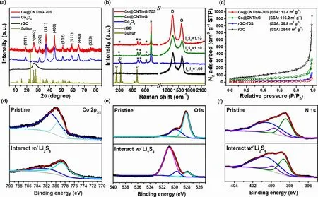
Figure 3. a) XRD spectra of Co@CNT/nG-70S in comparison with Co3O4, rGO and S. b) RAMAN spectra of Co@CNT/nG-70S in comparison with Co@CNT/nG, Co3O4 (marked by asterisks), rGO and S (marked by inverted triangles). c) N2 adsorption/desorption isotherms of Co@CNT/nG and rGO with before and after S loading. XPS spectra of d) Co 2p, e) O 1s and f) N 1s in Co@CNT/nG before and after adsorption with Li2S6.
In order to understand the redox promoter role of Co@CNT/nG with soluble LiPSs,cyclic voltammetry(CV)curve was collected configuring symmetrical cells with identical electrodes, in a 0.5 M Li2S6electrolyte, and within a voltage range of −1.0 to 1.0 V at a scan rate of 50 mV s−1.As shown in Figure 4a,the CV curve of the cell containing a Li2S6-free electrolyte exhibits negligible current response. The CV curve of a cell containing a Co@CNT/nG electrode in a Li2S6electrolyte achieves a higher current than the cell containing a rGO electrode,which indicates that the Co@CNT/nG-based cell achieves more facile conversion kinetics of LiPSs at the electrode surface. The enhanced redox reaction kinetics of LiPSs was also confirmed using electrochemical impedance spectroscopy(EIS)(Figure 4b).The charge transfer resistance (Rct) of Co@CNT/nG electrode with the smaller diameter is less than that of the rGO electrode, accordingly, the reduced Rctof the Co@CNT/nG electrode indicates enhanced charge transfer kinetics.[44]
In order to evaluate the inhibited LiPS shuttle of the Co@CNT/nG,the shuttle current was measured using a direct measurement process which has been previously reported.[45]The shuttle current was measured using a LiNO3-free electrolyte to prevent the production of passivation layers on the surface of the lithium.[46]As shown in Figure 4c,the shuttle current curve of the rGO-70S-based cell exhibits a sharp change between 2.5 and 2.3 V which is attributed to the formation of soluble, high-order chains of LiPSs that diffuse easily into the electrolyte. In contrast, the shuttle current of the Co@CNT/nG-70S-based cell was much lower than that of the rGO-70S-based cell and recorded small changes,indicating that the Co@CNT/nG-70S cathode effectively suppresses the LiPS shuttle effect during the charge/discharge process.
Quantitative Li2S deposition method was used to analyze the conversion kinetics of soluble LiPSs to solid Li2S.[47]As shown in Figure 4d,the peak of the potentiostatic current profile of the Co@CNT/nG-based cell appears after 1456 s, which is 108 s sooner than that of the rGObased cell.Furthermore,the Co@CNT/nG and rGO electrodes depositing Li2S achieved 128.4 and 104.4 mAh g−1, respectively (based on the weight of S in the catholyte). Based on the above results obtained for the color test, XPS, and cells, Co3O4NPs embedded in Co@CNT/nG synergistically combines LiPSs affinity with an ability to efficiently promote redox reaction kinetics of various S species. As a result, it is expected that Co@CNT/nG electrode will facilitate the redox conversion kinetics of LiPSs and improve the utilization efficiency of S.
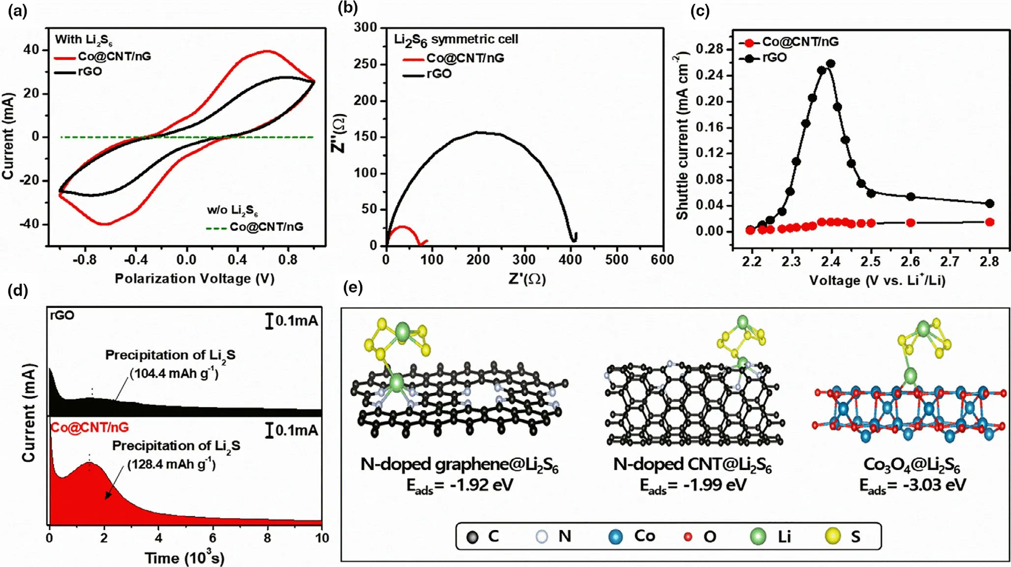
Figure 4. a) CV curves, b) Nyquist plots of symmetric cells with Co@CNT/nG and rGO. c) Shuttle current of Co@CNT/nG-70S and rGO-70S. d)Potentiostatic discharge curves of Li2S8 solution at 2.06 V of Co@CNT/nG and rGO e) Calculated Li2S6-adsorption structure on N-doped CNT, N-doped graphene and Co3O4.
In order to further understand the interactive chemistry between LiPSs and active sites in Co@CNT/nG,density-functional-theory(DFT)calculation was performed on the absorption energies of Li2S6at Ndoped CNT, (400) surface of Co3O4and N-doped graphene. In this study,the adsorption energy(Eads)of each sample derived from the following equation;
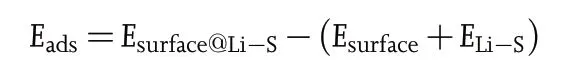
where Esurface@Li-Sis total energy of substrate which adsorbed Li2S6,Esurfaceis total energy of pristine substrate, and ELi-Swere total energies of Li2S6molecule, respectively. As presented in Figure 4e, the theoretical Li2S6-absorption energies of N-doped graphene,N-doped CNT and (400) surface of Co3O4are −1.92, −1.99 and −3.03 eV,respectively. These results imply that N-doped graphene, N-doped CNT, (400) surface of Co3O4and in Co@CNT/nG can successfully capture LiPSs to prevent the shuttling effect under the LSB systems.In particular, it was verified that (400) surface of Co3O4can deliver more outstanding inhibiting ability for the shuttling effect than the other active sites in Co@CNT/nG.These DFT calculation results confirm that the interconnecting CNT branches act as a buffer to delocalize stress concentration and play a role of inhibiting LiPS shuttle,thereby achieving long-term stability of Co@CNT/nG cathode under LSB systems.
In order to optimize the cobalt composition of Co@CNT/nG-70S,the amount of cobalt precursor was varied into 50, 75, 100, and 125 mg. As verified by initial galvanostatic charge–discharge (GCD)profiles and cycling performance at 0.1C, Co@CNT/nG-70S achieved the best cathode performance when the cobalt precursor of 75 mg was added (Figure S10). When the content of cobalt precursor was higher than 75 mg, the charge transfer resistance was enhanced to lower the specific capacity.On the other hand,at the lower content of cobalt precursor than 75 mg,the capacity was dropped during a long-term cycling due to the LiPS diffusion.Consequently,75 mg of cobalt precursor was thought to be the optimum composition.As determined by TGA curve(Figure S11),the Co content of Co@CNT/nG was about 22.4%.
CV test was conducted (S loading of 1.0–2.0 mg cm−2) at a scan rate of 0.1 mV s−1for first five cycles to investigate the electrochemical behavior of Co@CNT/nG-70S cathode.In order to verify the superiority of Co@CNT/nG-70S, other electrodes, including rGO-70S, Co3O4NPs deposited on rGO without CNT branches(Co/G-70S),and Co3O4NPs deposited on N-doped rGO without CNT branches (Co/nG-70S)were compared(Figure S12).The CV curves of the Co@CNT/nG-70Sbased cell (Figure 5a) show two reduction peaks at 2.35 and 2.04 V,which are attributed to the conversion of elemental S into soluble LiPSs and the further reduction of soluble LiPSs(Li2SX,4≤× ≤8)into insoluble Li2S2or Li2S, respectively.[48,49]On the other hand, two anodic peaks at 2.31 and 2.41 V are associated with the oxidation process from insoluble Li2S2or Li2S into soluble LiPS and further into S8.[50]Compared to the initial cycle, the reduction and oxidation peaks of the CV curves for the Co@CNT/nG-70S-based cell become slightly sharper with the higher intensities. Despite the similar multi-step conversion reaction, other cells, including rGO-70S, Co/G-70S, and Co/nG-70S,show weak current response and severe polarization.These different CV features of the respective electrodes even with the same S content are dependent on the chemical identities and compositions of hosting materials,which affect the redox kinetics and active sites.Furthermore,the CNT/nG electrode was prepared removing Co3O4NPs from Co@CNT/nG was prepared to further verify the structural superiority of unique 3D hierarchical structure of Co@CNT/nG(Figure S13).The CV curves of LSB cell with CNT/nG reveal large peak-to-peak separations and weak intensities, confirming the contribution of Co3O4NPs to the facile redox kinetics (Figure S14). In the successive cycles, the CV curves of Co@CNT/nG-70S-based cell show no significant change over five cycles, indicating a stable and reversible redox reaction (Figure S15). These CV results demonstrate that the multi-compositions of Co3O4NPs,interconnected CNT branches,and N-doping as well as 3D hierarchical porous structures are required to exhibit the facile and reversible redox kinetics.
The slopes of Tafel plots in cathodic and anodic reactions obtained from the initial CV profiles are analyzed to further understand the superior redox kinetics of Co@CNT/nG-70S (Figure S16). The cathodic and anodic slopes of the Co@CNT/nG-70S were 0.040 and 0.109 mV dec−1, respectively, smaller than those of the Co/nG-70S(0.064and0.113 mV dec−1),Co/G-70S(0.107and 0.114 mV dec−1), rGO-70S (0.145 and 0.125 mV dec−1), and CNT/nG (0.232 and 0.183 mV dec−1), respectively. Consequently, the results of CV and Tafel plots imply minimal polarization and better redox kinetics than that of the other-type-based electrodes.
The rate performance and the corresponding GCD profiles of Co@CNT/nG-70S-based LSBs at various current densities (from 0.1 to 5.0 C) in a voltage range of 2.8–1.7 V are shown in Figure 5b. With an increase in C-rate from 0.1 to 5.0 C, the discharge capacities of the Co@CNT/nG-70S-based LSBs are changed from 1193.1 to 453.8 mAh g−1, respectively. The capacity retention ratio of 52.0%(up to 3 C) for the Co@CNT/nG-70S-based cells was much higher than those of other-type-based cells(Table S2).As shown in Figure 5c,the GCD profiles of the Co@CNT/nG-70S-based LSBs show two distinct discharge plateaus,even at 5.0 C,and low polarization(ΔE),supporting enhanced redox kinetics and outstanding rate performance(Figure S17). In contrast, the Co/nG-70S-based cells deliver a slightly lower initial discharge capacity of 1101.5 mAh g−1at 0.1 C than that of Co@CNT/nG-70S-based ones and decrease rapidly to 114.9 mAh g−1at 3.0 C with the capacity retention ratio of 10.4%.The GCD profiles of the Co/nG-70S-based cells display the absence of second plateau at above 2.0 C and significant polarization due to the sluggish redox kinetics of LiPSs. Moreover, the capacity retentions of Co/G-70S-based and rGO-70S-based cells are 8.4% and 4.9%, respectively, which means more sluggish kinetics and polarization than Co/nG-70S-based and Co@CNT/nG-70S-based ones.These results confirm the superior multidimensional architecture and N-doping effect of Co@CNT/nG on the facile redox kinetics promoted by Co3O4NPs.
During a discharge process of LSB cells, the GCD profiles can be divided into two regions,corresponding to the lower discharge plateau(QL) and higher discharge plateau (QH). Ideally, the capacity in QHregion is three times higher than that in QLregion.[51]However, the value of QH/QLis <3 when the unfavorable reaction such as the irreversible loss of the active material and the sluggish redox reaction occurs.[52]Figure 5d shows the ratios of QH/QLat different current densities. At the current densities from 0.1 to 5 C, the values of the QH/QLratio for Co@CNT/nG were higher than those of others. The higher QH/QLratio of Co@CNT/nG further supports the facile and reversible conversion redox kinetics and the mitigated polysulfide diffusion.
In order to further comprehend the facile and reversible redox kinetics of Co@CNT/nG-70S,EIS data of LSB cells were analyzed in the frequency range of 106to 10−1Hz. As shown in Figure 5e, the Nyquist plots consist of oblique line at the low frequencies (Warburg impedance, Zw) and semicircle at the high-to-middle frequencies (charge transfer resistance, Rct). Obviously, the Rctvalue (29.4 Ω) of the Co@CNT/nG-70S-based cell is much smaller than those of others(Table S3),indicating the faster charge transfer kinetics.

Figure 5. a) CV curves, b) rate capabilities from 0.1 to 5.0 C of LSB cells with Co@CNT/nG-70S, Co/nG-70S, Co/G-70S and rGO-70S. c) High C-rate charge/discharge polarization voltage profiles of Co@CNT/nG-70S. d) Comparison of QH/QL ratio at various C-rates of Co@CNT/nG-70S, Co/nG-70S, Co/G-70S and rGO-70S. e) Nyquist plot curves of LSB cells before cycling from 106 to 10−1 Hz at room temperature. f) Relationship between real resistance (Z’) and inverse square root of angular speed (at ω−1/2) in the low-frequency region. g) CV curves of Co@CNT/nG-70S cathodes obtained in the range of 0.1–0.4 mV s−1. h)Plot of current values versus the square root of rates of Co@CNT/nG-70S, Co/nG-70S, Co/G-70S and rGO-70S at C2 peak in CV curves.
In addition to the charge transfer kinetics, ion diffusion is a key parameter to determine the facile redox kinetics.Figure 5f illustrates the linear relationship between real impedance(Z’)and frequency(ω−1/2)for the Co@CNT/nG-70S-based, Co/(n)G-70S-based, and rGO-70Sbased cells in the low-frequency region.The slope of this plot indicates the degree of Li+ion solid-state diffusion in the internal electrode.[53]The slope of the Co@CNT/nG-70S-based cell is 4.5,gentler than those of others, demonstrating the rapid ion diffusion kinetics. As shown in Figure 5g,the DLialso can be obtained from the analyses of CV curves at the scan rates from 0.1 to 0.4 mV s−1between 1.7 to 2.8 V,following the Randles-Sevcik equation as below(Figure S18):[54]
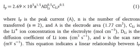
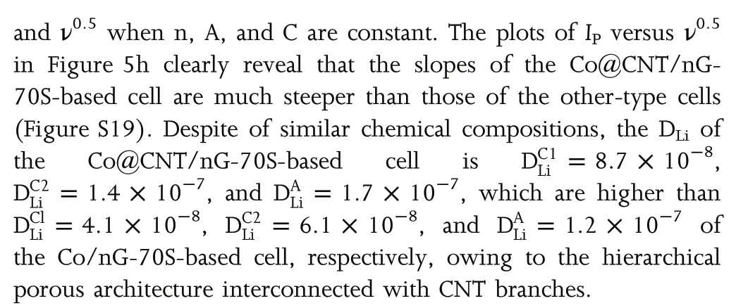

Figure 6. a) Cycling performances and Coulombic efficiencies at 0.1C and b) long-term cycling stability at 0.5C of LSB cells with Co@CNT/nG-70S, Co/nG-70S, Co/G-70S and rGO-70S. c) long-term cycling stability at 2 C and 5 C of LSB cells with Co@CNT/nG-70S. d) cycling performance at 0.2 C of Co@CNT/nG-70S cathode with different areal S loadings of 3.3, 4.6 and 6.5 mg cm−2. SEM images of the e) Co@CNT/nG-70S and f) rGO-70S and Li metal surface paired with g) Co@CNT/nG-70S and h) rGO-70S after 100 cycles and EDS elemental mapping of S corresponding to the SEM images (inset).
The cyclic stability was evaluated in order to confirm the structural integrity and mitigated LiPS diffusion of Co@CNT/nG electrode. As shown in Figure 6a,the Co@CNT/nG-70S-based LSBs deliver a higher initial discharge capacity of 1193.1 mAh g−1at 0.1 C,while the rGO-70S-based LSBs deliver an initial discharge capacity of only 878.3 mAh g−1. After 100 cycles, the Co@CNT/nG-70S-based LSBs demonstrated capacity retention of 80%with a high average coulombic efficiency (CE) of 98.6%, which is much higher and stable than those of the other-type-based LSBs (Table S4). The long-term cycle stability of the Co@CNT/nG-70S-based cell was compared with those of the other-type-based electrode at 0.5 C as shown in Figure 6b. The Co@CNT/nG-70S-based LSBs achieved a stable cycling performance with a high initial discharge capacity of 871.2 mAh g−1. After 450 cycles, the discharge capacity of Co@CNT/nG-70S-based cell was 615 mAh g−1,corresponding to 0.065%capacity fading per cycle.On the other hand,the Co/nG-70S-based cell delivered the specific capacity of 546 mAh g−1over 232 cycles, corresponding to 0.116% capacity fading per cycle. The Co/G-70S-based and rGO-70S-based cells exhibited the gradual decrease to 474 and 339 mAh g−1over 340 cycles,corresponding to 0.130 and 0.220% capacity fading per cycle, respectively. This indicates that the interconnecting CNT branches, Co3O4NPs, and N-doping of the Co@CNT/nG-70S effectively alleviate the LiPS shuttle effect and greatly improve long-term cycle durability. Furthermore, the long-term cycling stability of Co@CNT/nG-70S-based LSBs at high-current densities was evaluated after performing electrode activation during the initial 3 cycles at 0.2 C as shown in Figure 6c.After 700 cycles, the capacities of Co@CNT/nG-70S cathode at 2 and 5 C were 601.2 and 474.6 mAh g−1at the low-fading rates of 0.037%and 0.030% per cycle, respectively. The electrochemical performances of LSB batteries with Co@CNT/nG-70S were compared with those of previous reported literatures (Table S5). Among of the Co-based hosting materials with the similar loading and E/S ratio,LSB cells based on Co@CNT/nG achieved the best cyclic stability,indicating the superiority of the structural design. For the practical applications of LSBs, the electrochemical performance was evaluated at a high mass loading of(>4.0 mg cm−2), which can compete with up-to-date LIBs.[55]As shown in Figure 6d,the Co@CNT/nG-based LSB cells with the S loadings of 3.3, 4.6 and 6.5 mg cm−2delivered high areal capacities of 2.48, 3.97 and 5.62 mAh cm−2, respectively, at 0.2 C. After 100 cycles, these cells maintained areal capacities up to 2.16, 3.51 and 5.05 mAh cm−2, corresponding to capacity decay rates of 0.087%,0.098%and 0.084%per cycle,respectively.In particular,the high areal capacity of Co@CNT/nG-based LSB cells with 6.5 mg cm−2is comparable to that of commercial LIBs.
In order to support the structural integrity of the Co@CNT/nG electrode, post-mortem analyses were carried out by SEM and EDS characterizations. As shown in Figure 6e, the cycled Co@CNT/nG electrode shows uniform distribution of S after 100 charging and discharging cycles as indicated by the elemental mapping. The cycled Co/nG-70S based electrode also reveals even distribution of S, implying the positive effect of Co NPs and N-doping on S hosting (Figure S20a). However, some cracks which are caused by repeated volume expansion and contraction are observed on the surface of Co/nG-70S electrode as marked by a red arrow. Both rGO-70S and Co/G-70S electrodes reveal local aggregation of S, resulting in serious capacity degradation during the cycling process (Figure 6f and Figure S20b). For the analysis on the LiPS shuttle, the surface of Li anode paired with the Co@CNT/nG cathode is observed after cycling (Figure 6g). Li anode relatively shows smooth surface without formation of Li2S passivation layers, because Co@CNT/nG-70S cathode effectively alleviates the LiPS shuttle. On the other hand, the surface of Li anode paired with the other-type based cathodes after cycling is very rough, which is caused by the formation of a Li2S/Li2S passivation layer on the anode surface arising from the continuous reaction between Li and soluble LiPS (Figure 6h and Figure S20c,d). These results confirm that the interconnecting CNT branches act as a buffer to delocalize stress concentration and play a role of inhibiting LiPS shuttle, thereby achieving long-term stability.
3. Conclusions
In summary, we have demonstrated a multidimensional hybrid architecture of Co@CNT/nG, which is comprised of Co3O4NPs encapsulated in the tube of CNT branches interconnecting N-doped rGO,for S host of LSBs. The functional roles of multidimensional Co@CNT/nG architecture are schematically illustrated as shown in zoomed image of Figure 1. Firstly, Co3O4NPs achieved the strong LiPS affinity and the facilitated conversion reaction kinetics for the inhibited LiPS shuttle and the improved S utilization.Secondly,the interconnecting CNT branches offered the rapid electron/ion transporting channels for the more facile redox kinetics and the volumetric buffer for the delocalized stress release. Finally, N-doping and hierarchical porous structure assisted to alleviate LiPS shuttle and to promote the conversion reaction kinetics.These functionalities have been confirmed through various measurements including symmetric cells,Li2S nucleation,shuttle currents,Tafel slopes, diffusion coefficients, and post-mortem analyses. Consequently,the Co@CNT/nG-70S-based LSB cells delivered a high specific capacity of 1193.1 mAh g−1at 0.1 C,a high rate capacity of 453.8 mAh g−1at 5.0 C, and a long cyclic stability of 0.065% capacity fading per cycle for 450 cycles at 0.5 C.Furthermore,the Co@CNT/nG-70S-based LSB even with 6.5 mg cm−2delivered the high areal capacity of 5.62 mAh cm−2for practical applications. This research provides a rational material design chemistry to construct multidimensional architectures and hybrid compositions of functional nanomaterials accommodating high-capacity active materials.
4. Experimental Section
Synthesis of Co@CNT/nG-70S: The Co@CNT/nG was prepared according to a simple method. First, 75 mg (or 0.258 mmol) Co(NO3)2∙6H2O (cobalt(II) nitrate hexahydrate, JUNCEI) and 200 mg (2.38 mmol) DCDA (dicyandiamide, Sigma-Aldrich)were dissolved in a 20 mL graphene oxide(GO)solution of 0.5 wt%in a 70 mL vial.The solution was then sonicated for 30 min.Next,a magnetic bar was placed in the vial and used to stir the solution(at more than 500 rpm)at room temperature for approximately 1 h on a hot plate.The solution then freeze-dried for 3 days. Subsequently, the freeze-dried sample was heated in an alumina boat under Ar atmosphere. The mixture was heated to 400 °C for 2 h. Then, it was further heated to 900 °C for 1 h. After heat treatment,the sample cooled naturally. To make Cobalt oxide NPs, sample was reheated to 350 °C for 2 h under Air atmosphere (Co@CNT/nG). The Co@CNT/nG-70S synthesis is prepared by mixing Co@CNT/nG and S at a weight ratio of 1:2.3,and subsequently heated at 155 °C for 12 h and 160 °C for 2 h in a closed Teflon bottle filled with Ar gas(Figure 1-E). In order to demonstrate the optimum content of Co3O4NPs, 50,100 and 100 mg of Co(NO3)2∙6H2O also prepared under the sample conditions as above mentioned.
Synthesis of Co/nG-70S: The DCDA used in the Co@CNT/nG synthesis process was replaced with UREA.75 mg Co(NO3)2∙6H2O and 285.88 mg(4.76 mmol)Urea(DAEJUNG)were dissolved in a 20 mL GO solution of 0.5 wt%in a 70 mL vial.The following process was carried out under the sample condition as above.
Synthesis of Co/G-70S: 75 mg Co(NO3)2∙6H2O was dissolved in a 20 mL GO solution of 0.5 wt%in a 70 mL vial.The following process was carried out under the sample condition as above.
Synthesis of rGO-70S: 20 mL GO solution of 0.5 wt% put in a 70 mL vial.The rGO was prepared according to a simple method.
Acknowledgements
J.S.Y and Y.H.K.are authors contributed equally to this work.This work was financially supported by the National Research Foundation of Korea(NRF)grant funded by the Korea Government(MSIT)(NRF-2020R1A3B2079803),Republic of Korea.
Conflict of Interest
The authors declare no conflict of interest.
Supporting Information
Supporting Informationis available from the Wiley Online Library or from the author.
Keywords
graphene/CNThybrid,lithium–sulfurbatteries,multidimensional architecture, nanoparticle encapsulation, redox promoter
Received: January 21, 2021
Revised: March 8, 2021
Published online: March 9, 2021
[1] P. G. Bruce, S. A. Freunberger, L. J. Hardwick, J.-M. Tarascon, Nat. Mater.2012, 11, 19–29.
[2] H. Zhao, N. Deng, J. Yan, W. Kang, J. Ju, X. Ruan, X. Wang, Q. Zhuang,B. C. Li, Chem. Eng. J. 2018, 347, 343–365.
[3] X. Ji, L. F. Nazar, J. Mater. Chem. 2010, 20, 9821–9826.
[4] M. Hagen, D. Hanselmann, K. Ahlbrecht, R. Maça, D. Gerber, J. T¨ubke,Adv. Energy Mater. 2015, 5, 1401986.
[5] H. J. Peng, J. Q. Huang, X. B. Cheng, Q. Zhang, Adv. Energy Mater. 2017,7, 1700260.
[6] M. Zhao, B.-Q. Li, H.-J. Peng, H. Yuan, J.-Y. Wei, J.-Q. Huang, Angew.Chem. Int. Ed. 2020, 59, 12636–12652.
[7] Q. Xiao, G. Li, M. Li, R. Liu, H. Li, P. Ren, Y. Dong, M. Feng, Z. Chen, J.Energy. Chem. 2020, 44, 61–67.
[8] Z. Lyu, D. Xu, L. Yang, R. Che, R. Feng, J. Zhao, Y. Li, Q. Wu, X. Wang,Z. Hu, Nano Energy. 2015, 12, 657–665.
[9] G. Zheng, Q. Zhang, J. J. Cha, Y. Yang, W. Li, Z. W. Seh, Y. Cui, Nano Lett. 2013, 13, 1265–1270.
[10] W. Ahn, K.-B. Kim, K.-N. Jung, K.-H. Shin, C.-S. Jin, J. Power Sources 2012, 202, 394–399.
[11] J. Liu, S. Xiao, L. Chang, L. Lai, R. Wu, Y. Xiang, X. Liu, J. S. Chen, J.Energy Chem. 2021, 56, 343–352.
[12] L. Ji, M. Rao, H. Zheng, L. Zhang, Y. Li, W. Duan, J. Guo, E. J. Cairns, Y.Zhang, J. Am. Chem. Soc. 2011, 133, 18522–18525.
[13] D. Xiao, Q. Li, H. Zhang, Y. Ma, C. Lu, C. Chen, Y. Liu, S. Yuan, J. Mater.Chem. A 2017, 5, 24901–24908.
[14] G. Zhou, Y. Zhao, A. Manthiram, Adv. Energy Mater. 2015, 5, 1402263.
[15] F. Wu, J. Li, Y. Tian, Y. Su, J. Wang, W. Yang, N. Li, S. Chen, L. Bao, Sci Rep 2015, 5, 13340.
[16] C.-P. Yang, Y.-X. Yin, H. Ye, K.-C. Jiang, J. Zhang, Y.-G. Guo, A. C. S.Appl, Mater. Interfaces 2014, 6, 8789–8795.
[17] B. Yuan, D. Hua, X. Gu, Y. Shen, L.-C. Xu, X. Li, B. Zheng, J. Wu, W.Zhang, S. Li, F. Huo, J. Energy Chem. 2020, 48, 128–135.
[18] M. Zhao, H.-J. Peng, B.-Q. Li, X. Chen, J. Xie, X. Liu, Q. Zhang, J.-Q.Huang, Angew. Chem. Int. Ed. 2020, 59, 9011–9017.
[19] B.-Q. Li, L. Kong, C.-X. Zhao, Q. Jing, X. Chen, H.-J. Peng, J.-L. Qin, J.-X.Chen, H. Yuan, Q. Zhang, J.-Q. Huang, InfoMat. 2019, 1, 533–541.
[20] X. Tao, J. Wang, C. Liu, H. Wang, H. Yao, G. Zheng, Z. W. Seh, Q. Cai,W. Li, G. Zhou, Nat. Commun. 2016, 7, 11203.
[21] Y. Gogotsi, ACS Nano 2014, 8, 5369–5371.
[22] S. H. Li, X. H. Xia, Y. D. Wang, X. L. Wang, J. P. Tu, J. Power Sources 2017, 342, 224–230.
[23] S.-H. Lee, V. Sridhar, J.-H. Jung, K. Karthikeyan, Y.-S. Lee, R. Mukherjee,N. Koratkar, I.-K. Oh, ACS Nano 2013, 7, 4242–4251.
[24] C. Li, G. Shi, Nanoscale 2012, 4, 5549–5563.
[25] B. J. Landi, M. J. Ganter, C. D. Cress, R. A. DiLeo, R. P. Raffaelle, Energy Environ. Sci. 2009, 2, 638–654.
[26] P. Bhattacharya, D. H. Suh, P. Nakhanivej, Y. Kang, H. S. Park, Adv.Funct. Mater. 2018, 28, 1801746.
[27] P. Su, H. Xiao, J. Zhao, Y. Yao, Z. Shao, C. Li, Q. Yang, Chem. Sci. 2013,4, 2941–2946.
[28] A. Gohier, C. P. Ewels, T. M. Minea, M. A. Djouadi, Carbon 2008, 46,1331–1338.
[29] Y. Zan, Z. Zhang, H. Liu, M. Dou, F. Wang, J. Mater. Chem. A 2017, 5,24329–24334.
[30] C. Oh, N. Yoon, J. Choi, Y. Choi, S. Ahn, J. K. Lee, J. Mater. Chem. A 2017, 5, 5750–5760.
[31] C. Liu, C. Wang, J. Tang, J. Zhang, Q. Shang, Y. Hu, H. Wang, Q. Wu, Y.Zhou, W. Lei, Z. Liu, Polymers 2018, 10, 1288.
[32] K. Balakumar, N. Kalaiselvi, RSC Adv. 2015, 5, 34008–34018.
[33] A. Numan, N. Duraisamy, F. S. Omar, Y. K. Mahipal, K. Ramesh, S.Ramesh, RSC Adv. 2016, 6, 34894–34902.
[34] S. B. Turcotte, R. E. Benner, A. M. Riley, J. Li, M. E. Wadsworth, D. Bodily, Appl. Optics 1993, 32, 935–938.
[35] J. Xu, D. Su, W. Zhang, W. Bao, G. Wang, J. Mater. Chem. A 2016, 4,17381–17393.
[36] S. Yun, S. M. Bak, S. Kim, J. S. Yeon, M. G. Kim, X. Q. Yang, P. V. Braun,H. S. Park, Adv. Energy Mater. 2019, 9, 1802816.
[37] M. Zhang, C. Yu, C. Zhao, X. Song, X. Han, S. Liu, C. Hao, J. Qiu, Energy Storage Mater. 2016, 5, 223–229.
[38] Z. Li, C. Li, X. Ge, J. Ma, Z. Zhang, Q. Li, C. Wang, L. Yin, Nano Energy 2016, 23, 15–26.
[39] O. Ogoke, S. Hwang, B. Hultman, M. Chen, S. Karakalos, Y. He, A. Ramsey, D. Su, P. Alexandridis, G. Wu, J. Mater. Chem. A 2019, 7,13389–13399.
[40] Z. Chang, H. Dou, B. Ding, J. Wang, Y. Wang, X. Hao, D. R. MacFarlane,J. Mater. Chem. A 2017, 5, 250–257.
[41] D. Luo, G. Li, Y. P. Deng, Z. Zhang, J. Li, R. Liang, M. Li, Y. Jiang, W.Zhang, Y. Liu, A. Y. Wen Lei, Z. Chen, Adv. Energy Mater. 2019, 9,1900228.
[42] D. Li, D. Yang, X. Zhu, D. Jing, Y. Xia, Q. Ji, R. Cai, H. Li, Y. Che, J. Mater.Chem. A 2014, 44, 18761–18766.
[43] W. Yang, W. Yang, B. Sun, S. Di, K. Yan, G. Wang, G. Shao, A. C. S.Appl, Mater. Interfaces 2018, 10, 39695–39704.
[44] W. Li, J. Qian, T. Zhao, Y. Ye, Y. Xing, Y. Huang, L. Wei, N. Zhang, N.Chen, L. Li, F. Wu, R. Chen, Adv. Sci. 2019, 6, 1802362.
[45] D. Moy, A. Manivannan, S. R. Narayanan, J. Electrochem. Soc. 2014, 162,A1–A7.
[46] S. S. Zhang, Electrochim. Acta 2012, 70, 344–348.
[47] F. Y. Fan, W. C. Carter, Y.-M. Chiang, Adv. Mater. 2015, 27, 5203–5209.
[48] Q. Sun, X. Fang, W. Weng, J. Deng, P. Chen, J. Ren, G. Guan, M. Wang,H. Peng, Angew. Chem. 2015, 127, 10685–10690.
[49] F. Zeng, K. Yuan, A. Wang, W. Wang, Z. Jin, Y.-S. Yang, J. Mater. Chem.A 2017, 5, 5559–5567.
[50] J. Shim, K. A. Striebel, E. J. Cairns, J. Electrochem. Soc. 2002, 149,A1321–A1325.
[51] T. An, D. Deng, M. Lei, Q.-H. Wu, Z. Tian, M. Zheng, Q. Dong, J. Mater.Chem. A 2016, 4, 12858–12864.
[52] H. You, M. Shi, J. Hao, H. Min, H. Yang, X. Liu, J. Alloy. Compd. 2020,823, 153879.
[53] Y.-S. Lee, K.-S. Ryu, Sci. Rep. 2017, 7, 16617.
[54] H. Kim, J. Lee, H. Ahn, O. Kim, M. J. Park, Nat. Commun. 2015, 6, 7278.
[55] J. S. Yeon, T. H. Park, Y. H. Ko, P. Sivakumar, J. S. Kim, Y. Kim, H. S.Park, J. Energy Chem. 2021, 55, 468.
 Energy & Environmental Materials2022年2期
- Energy & Environmental Materials的其它文章
- Progress of Pb-Sn Mixed Perovskites for Photovoltaics:A Review
- Development Strategies in Transition Metal Borides for Electrochemical Water Splitting
- Polymer-/Ceramic-based Dielectric Composites for Energy Storage and Conversion
- Controllable Construction of Bifunctional CoxP@N,P-Doped Carbon Electrocatalysts for Rechargeable Zinc–Air Batteries
- Unveiling the Underlying Mechanism of Transition Metal Atoms Anchored Square Tetracyanoquinodimethane Monolayers as Electrocatalysts for N2 Fixation
- Rational Design of High-Performance Bilayer Solar Evaporator by Using Waste Polyester-Derived Porous Carbon-Coated Wood