
Forging Inspired Processing of Sodium-Fluorinated Graphene Composite as Dendrite-Free Anode for Long-Life Na–CO2 Cells
2022-07-04 09:13YangjunMaoXiaoChenHaoChengYunhaoLuJianXieTaoZhangJianTuXiongwenXuTiejunZhuandXinbingZhao
Energy & Environmental Materials 2022年2期
Yangjun Mao, Xiao Chen, Hao Cheng, Yunhao Lu, Jian Xie* , Tao Zhang, Jian Tu,Xiongwen Xu, Tiejun Zhu, and Xinbing Zhao
1. Introduction
With the increasing use of fossil fuels, a considerable amount of CO2has been expelled into the atmosphere, leading to global climate change.[1]To address this problem, massive efforts have been made to realize CO2reduction and utilization.[2–15]In recent years, Li–CO2batteries based on the reaction of Li and CO2(4Li + 3CO2↔2Li2CO3+ C)become exceedingly attractive because of the high theoretical energy density (1876 Wh kg-1) and clean utilization of CO2.[16–19]Li–CO2batteries originated from the research by Takechi et al.,[17]who found that CO2addition in Li–O2batteries increased the discharge capacity and energy density. Subsequently, Liu et al.[19]reported the first rechargeable Li–CO2battery with the organic electrolyte at room temperature. As reported by Zhou group, the decomposition of Li2CO3can proceed through an irreversibleprocessviaareaction 2Li2CO3→2CO2+ O2+ 4Li++ 4e-when using carbon catalyst, instead of a reversible reaction of 2Li2CO3+ C →4Li++ 3CO2+4e-when using Ru catalyst.[20]This interesting work suggests that CO2fixation can be realized through Li–CO2batteries.
Considering the fact that Na is one of the most abundant elements in the earth’s crust and costs only about 10%of Li,[21]Na–CO2battery is regarded as a promising alternative to Li–CO2battery.[22–24]Similar to Li–CO2batteries, the reversible reaction of Na–CO2batteries has proved to be 3CO2+ 4Na ↔2Na2CO3+ C.In comparison,Na–CO2batteries have a lower reaction Gibbs free energy than Li–CO2batteries,which offers the possibility to realize lower charge potential without electrolyte decomposition.[25]Meanwhile, Na–CO2batteries can deliver a high theoretical energy density of 1125 Wh kg-1, though not as high as Li–CO2batteries.[25–27]Despite these advantages, Na–CO2battery system suffers from serious security issues caused by Na dendrite growth.[28,29]Recently,numerous researches are in progress to investigate the key factors required to stabilize the solid–liquid interface between Na metal and organic electrolyte.[30–33]Hartmann et al.and Bi et al.revealed that the formation of Na dendrites would cause an internal short circuit by penetrating through the separator.[34,35]Zhao et al.[36]confirmed that the Na dendrite formation becomes more severe at a higher depth of discharge and after longer cycling.
Sharing the homologous methods for achieving stable Li anodes,[37–43]various approaches,such as using electrolyte additives or building an artificial solid electrolyte interface(SEI)layer,are developed to enhance stability of Na anodes.[44–46]Among multifarious electrolyte additives, fluorine-containing salts or solvents have been employed to acquire highly reversible Li/Na metal electrodes.[33,47–53]It is believed on most occasions that those salts/solvents act as an F-donor and F is a requisite for building a stable and robust SEI layer. The fluorinated salts/solvents decompose on the surface of Li/Na metal with the formation of a LiF-or NaF-rich SEI layer.[54–57]The low solubility in aprotic solvents may be the reason for the stabilizing effect of LiF/NaF. However, these fluorinated salts/solvents are chemically unstable and tend to decompose to produce toxic components, which is unfavorable for the environment.[58]Therefore, alternative methods for constructing NaF-rich SEI layer on Na metal are required.
Herein, we report a facile, environmentally friendly method to in situ fabricate a stable,NaF-rich SEI layer on metallic Na by introducing a small amount of fluorinated graphene(FG)in Na.Inspired by the conventional forging processing, a uniform Na/FG composite was obtained by melting and repetitive FG-adsorbing/hammering processes. Na/FG–Na/FG half cells can sustain an areal capacity as high as 5 mAh cm-2for over 700 h at a current density up to 5 mA cm-2.Na–CO2full cell with the Na/FG anode can be stably cycled for 391 cycles with a limited capacity of 1000 mAh g-1at 200 mA g-1. The long cycle life of the cells can be attributed to the protecting effect of the in situ constructed NaF-rich SEI layer for metallic Na.The formation of the SEI layer was confirmed by both experiments and density functional theory (DFT) calculations. The NaF-rich SEI layer was found to be effective in inhibiting the Na dendrites as verified by in situ optical microscopy observations. This work will shed light on the design of dendrite-free Na anodes for high-performance metallic sodium batteries.
2. Results and Discussion
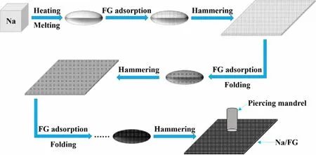
Figure 1. Schematic illustration of the processing of Na/FG electrode.
As is known, iron metal can be shaped by heating and hammering in conventional forging. Inspired by this cognition, we introduce a facile and practical method to process Na/FG composite anode. Bulk Na was first melted into an ellipsoid shape at about 250 °C and mixed with the FG powder by a simple absorbing process. After cooling, the Na/FG composite was mechanically hammered to sheet.After adsorbing FG again, the Na/FG sheet was folded into ellipsoid followed by hammering. A uniform Na/FG composite was obtained through repetitive adsorbing FG, folding, and hammering steps as shown in Figure 1. The mass proportion of FG in the composite anode is about 3 wt% which is determined using a precise balance.And the morphology of pristine FG is displayed in Figure S1 (supporting information). As seen in Figure 2a–d, both the surface and cross section of bare Na are coarse. The presence of FG in the Na/FG composite was confirmed by both surface and cross-sectional scanning electron microscope (SEM) observations (Figure 2f,h). It can be seen from the insets in Figure 2a,e that the color of the Na becomes black with FG.
The electrochemical performance of the Na/FG electrode was evaluated using Na–CO2full cells with the δ-MnO2cathode. Figure 3a illustrates the X-ray diffraction (XRD) patterns of the cathodes of the Na–CO2cells at different states with the Na/FG anodes. At the pristine state, the three strong diffraction peaks at 12.7°, 18.1°, and 37.6° (2θ) can be indexed as the δ-MnO2phase (JCPDS No. 72-1982). XRD patterns of the discharge electrode confirm that the discharge product of the Na–CO2cell is Na2CO3. After recharge, the XRD patterns show no obvious difference with those of the pristine state, suggesting complete decomposition of the Na2CO3. The work by Sun et al.[27]also confirmed full decomposition of Na2CO3upon charge. The voltage profiles of the Na–CO2cells with Na/FG and bare Na anodes with a limited capacity of 1000 mAh g-1at 200 mA g-1between 1.5 and 4.5 V are shown in Figure 3b–d. For the cell with bare Na anode, although it can be cycled stably in the initial 100 cycles, the charge/discharge terminal voltages reach their cutoff values (1.5–4.5 V). In comparison, the cell with Na/FG anode can sustain a stable cycling up to 391 cycles before reaching the cutoff voltages. It should be noted that the cycle life of the Na–CO2cell increases by 50% with only ~3 wt% FG in Na anode. As seen in Figure S2, the Na–CO2cell with MnO2cathode and Na/FG anode can deliver a first discharge capacity of 7174 mAh g-1(discharge to 1.8 V) and a corresponding charge capacity of 6976 mAh g-1(charge to 4.1 V). From Figure S3a, it can be seen the Na/MnO2cell can deliver a capacity of 2895 mAh g-1(discharge to 1.6 V) in pure CO2(namely, the Na–CO2cell) at 400 mA g-1. In contrast, the cell shows a much lower capacity of only 276 mAh g-1(Figure S3b),when tested in pure Ar, where MnO2acts only as the intercalation cathode for Na/MnO2cell, inferring that the Na-intercalation in MnO2contributes to only a small proportion of total capacity of the Na–CO2cell (in CO2). XRD patterns of Na anode from the dead cell with Na anode (Figure S4)reveal that the Na has been converted into NaOH and NaOH∙H2O.To highlight the excellent electrochemical performance of our Na–CO2cells with Na/FG anode, cycle life of Na–CO2cells with different catalysts and Na anodes is compared as summarized in Table S1.Clearly, the electrochemical performance of our Na–CO2cell is among the best in view of the applied current density, limited capacity value, and the use of costeffective MnO2catalyst. It is clear that a long cycle life of the cell is closely related to the stable Na/FG anode as discussed later. It is expected that the cycle life can be further improved by adding suitable redox mediators Li–O2batteries[59,60]or using a hybrid electrolyte with solid electrolyte as a separator.[61]
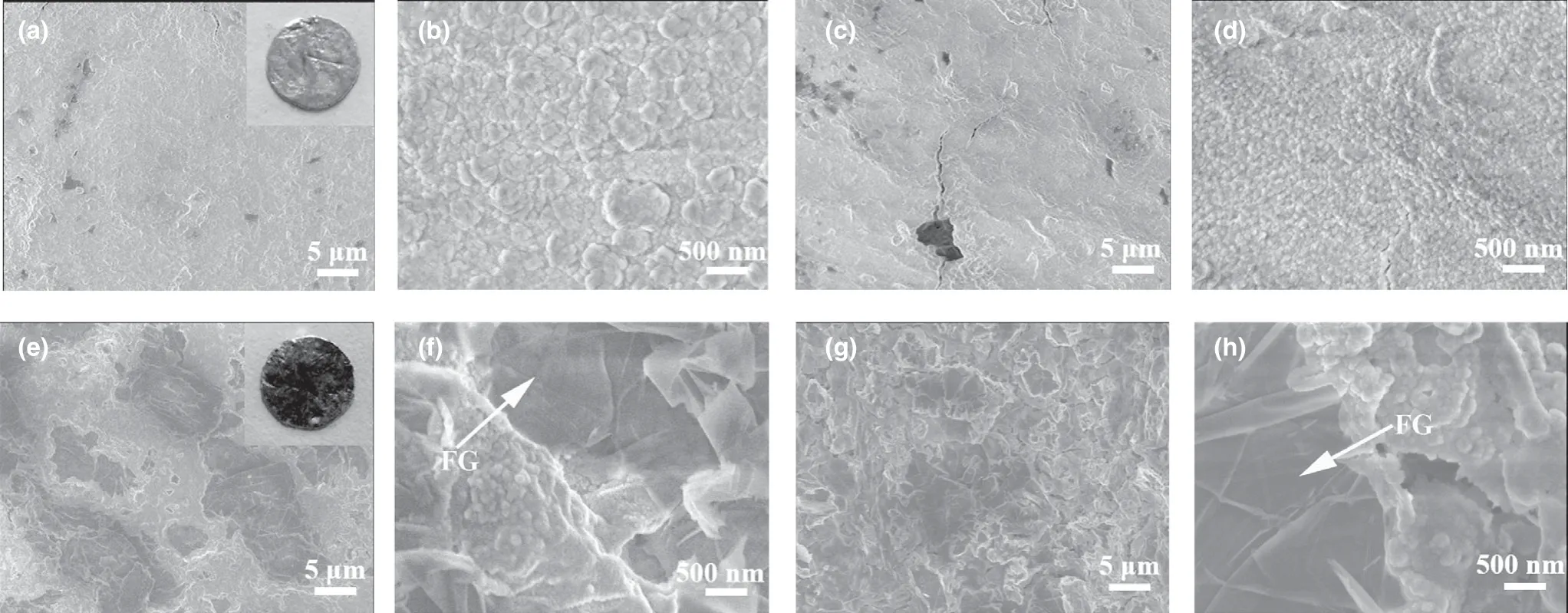
Figure 2. a, b) Surface and c, d) cross-sectional SEM images of bare Na electrode, and e, f) surface and g, h) cross-sectional SEM images of Na/FG electrode.
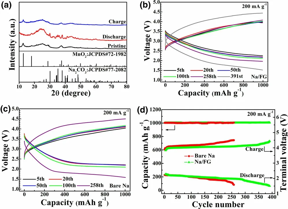
Figure 3. a) XRD patterns of the MnO2 cathodes of the Na–CO2 cells at different states with Na/FG anode, b, c) voltage profiles, and d) cycling performance of Na–CO2 cells with bare Na and Na/FG anodes at 200 mA g-1 with a limited capacity of 1000 mAh g-1.
SEM images of the MnO2cathodes of the Na–CO2cells at different states with Na/FG anode are displayed in Figure S5. As presented in Figure S5a, the δ-MnO2has a nanoflake structure that was grown directly on the surface of carbon fibers of the carbon cloth. The flake structure of the δ-MnO2provides numerous reaction sites and deposition sites for the discharge products (Na2CO3and C). With the increasing discharge capacity, the Na2CO3starts to form and grow. The formation of Na2CO3is confirmed by XRD in Figure 3a.When the discharge capacity rises to 1000 mAh g-1, thicker and larger Na2CO3bulks are deposited on the surface of δ-MnO2. During the charge process, the size of the Na2CO3bulks decreases gradually. At the complete charge state (discharge to 1000 mAh g-1capacity and subsequently recharge to 1000 mAh g-1capacity, Figure S5g), no Na2CO3bulks can be observed, agreeing well with the XRD results. The above result indicates that the carbon clothsupported δ-MnO2catalyst is highly efficient in catalyzing the formation/decomposition of Na2CO3, which makes it possible to investigate the intrinsic mechanism of FG addition for the performance improvement of the Na–CO2cells more accurately.
To study the protecting effect of FG incorporation on stability of Na electrode,the stability of bare Na and Na/FG electrodes was first investigated by exposing the electrodes with the same size in open air(relative humidity = 60%). The morphology changes of bare Na and Na/FG electrodes in open air are illustrated in Figure 4a,and the phase evolution of the electrodes was checked by XRD as shown in Figure 4b–e.From Figure 4b,we can see that only the diffraction peaks of Na can be found in the initial electrodes.The surfaces of both bare Na and Na/FG become damp after being placed in open air for 30 min. At this time,NaOH constitutes the main component of both electrodes and the peaks related to Na2CO3begin to emerge (Figure 4c). After 8 h, the surfaces of bare Na and Na/FG become dry because of the weathering of Na2CO3. At the same time, the size of bare Na decreases sharply. In comparison,size decrease of the Na/FG electrode is much smaller.XRD patterns of the 8 h electrode(Figure 4d)demonstrate that NaOH dominates the main component of bare Na electrode, while for Na/FG,almost all the NaOH has been converted into Na2CO3.After air exposure for 16 h,the weight loss of bare Na is much larger than that of Na/FG.Meanwhile, the components of the Na/FG electrode remain nearly unchanged, while a new phase of Na2CO3∙H2O appears for bare Na(Figure 4e).The component evolution of bare Na and Na/FG electrodes in air results from the reactions between Na and O2, CO2,and H2O. A conclusion can be drawn that Na/FG electrode is easier to keep its shape with the introduction of FG and the protecting effect of FG plays an important role in keeping stability of Na/FG in open air,which is favorite for the practical applications of Na–CO2cells.
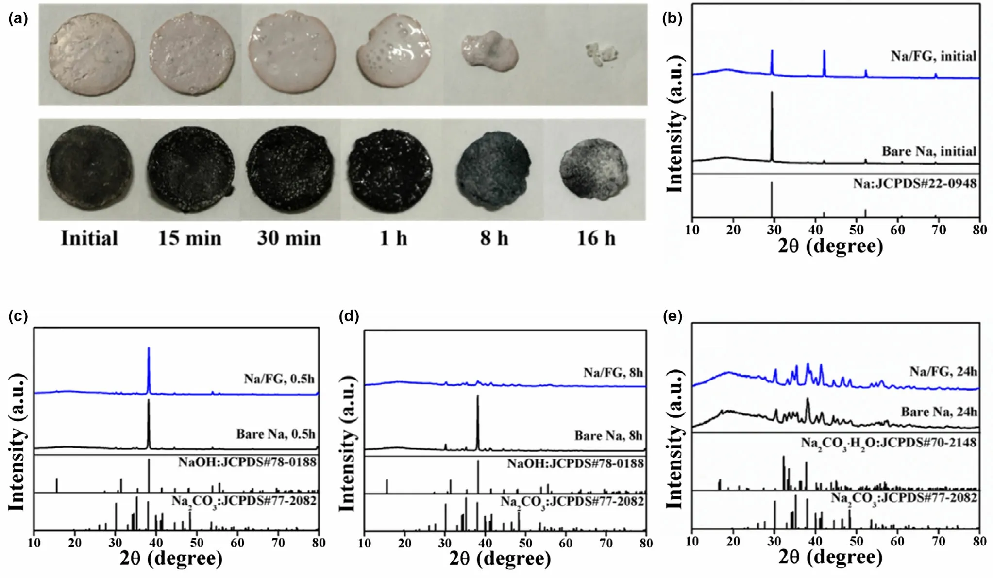
Figure 4. a) Morphology changes and b–e) XRD patterns of bare Na and Na/FG electrodes after exposure in open air for different durations.
To assess the effect of FG addition on cycling performance of Na electrodes,galvanostatic cycling of symmetric cells using bare Na and Na/FG electrodes was performed.Figure 5a,b shows the charge/discharge profiles of the symmetric cells with bare Na and Na/FG electrodes at 0.5 mA cm-2with a capacity of 1 mAh cm-2and at 5 mA cm-2with a capacity of 5 mAh cm-2, respectively. For the bare Na symmetric cell at 0.5 mA cm-2, the voltage hysteresis is as high as 150 mV at the beginning of cycling, along with a sharp decline after 25 cycles. As the cycle number increases, the voltage hysteresis enlarges gradually. After 250 cycles, a rapid rise of voltage hysteresis to over 200 mV occurs. For the Na/FG symmetric cell, the voltage hysteresis experiences a slow increase from 22 to 60 mV after 1400 h, demonstrating excellent cycling performance of Na/FG electrode at a relatively low current density.At a high current density of 5 mA cm-2, the voltage hysteresis of bare Na symmetric cell maintains a high value of over 350 mV during cycling for more than 700 h,while that of the Na/FG symmetric cell has a much smaller value ranging from 110 to 140 mV for more than 700 h with a slight fluctuation.From these comparisons,it can be deduced that the Na/FG electrode possesses better cycling performance and lower polarization than the bare Na electrode especially at a high current density and high areal capacity.
SEM characterizations of bare Na and Na/FG electrodes after 50 cycles of at 0.5 mA cm-2with 1 mAh cm-2areal capacity were performed to check the surface morphology changes. From Figure 5c,d, Na dendrites in large size, that is the “dead Na,” can be found on the surface of bare Na because of the heterogeneous Na stripping/plating behavior during cycling. Figure 5e,f reveals the presence of fractures and holes on the cross section of bare Na electrode, further confirming inhomogeneous Na stripping and plating. For Na/FG, no Na dendrites can be seen on the surface of the electrode (Figure 5g,h). Besides, the cross-sectional SEM images of Na/FG (Figure 5i,j) exhibit an intact and compact appearance,implying uniform stripping/plating behavior of Na and remarkable suppression of Na dendrite formation. According to the SEM observations, we can conclude that the FG plays a critical role in maintaining uniform Na stripping/plating and restraining Na dendrite growth.
Electrochemical impedance spectroscopy (EIS) measurements were carried out to characterize the impedance variations of the symmetric cells using bare Na and Na/FG electrodes at 0.5 mA cm-2with a capacity of 1 mAh cm-2(Figure 6a,b). The equivalent circuit for fitting of the Nyquist plots is given in Figure S6, where Restands for the internal ohm resistance of the cell, Rfand Q1represent surface film resistance and relaxation capacitance, and Rctand Q2correspond to the charge transfer resistance and double-layer capacitance.The fitting results were summarized in Table S2, where Rsurfacerepresents the electrode surface resistance comprising Rfand Rct. As manifested in Table S2, the surface resistances of the symmetric cell with bare Na are 784.7, 1817.5, 3589.1 Ω after 5, 20, 50 cycles,respectively. For the symmetric cell with Na/FG electrode, there is no obvious difference between the resistance after 5 cycles (658.2 Ω) and that after 20 cycles (654.9 Ω), while the value increases to 1007.1 after 50 cycles. It can be clearly seen that the resistance of the symmetric cell with Na/FG diminishes evidently compared to those of the symmetric cell with bare Na. The lower surface resistance of the symmetric cell with Na/FG electrode can be attributed to the construction of a robust and uniform SEI layer.
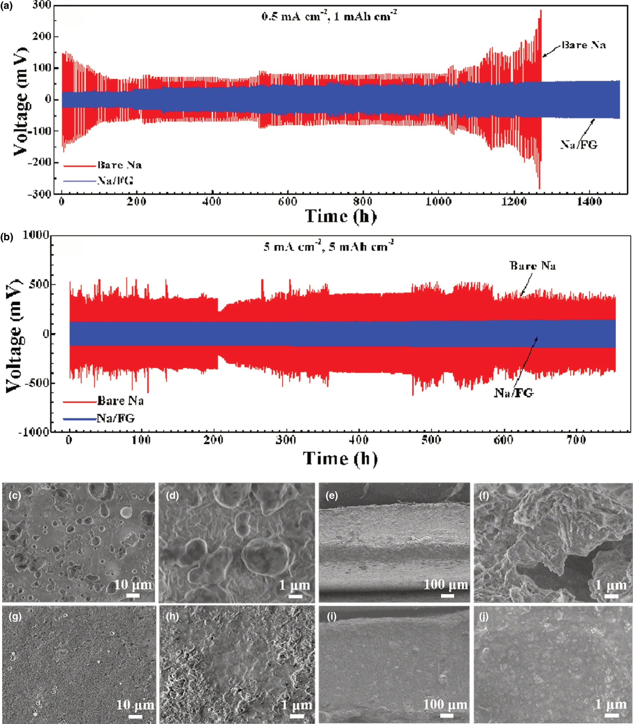
Figure 5. Galvanostatic charge/discharge profiles of bare Na and Na/FG electrodes at a) 0.5 mA cm-2 with a capacity of 1 mAh cm-2 and b) 5 mA cm-2 with a capacity of 5 mAh cm-2 in symmetric cells, c, d) surface and e, f) cross-sectional SEM images of bare Na electrode at 0.5 mA cm-2 with 1 mAh cm-2 capacity after 50 cycles, and g, h) surface and i, j) cross-sectional SEM images of Na/FG electrode at 0.5 mA cm-2 with 1 mAh cm-2 capacity after 50 cycles.
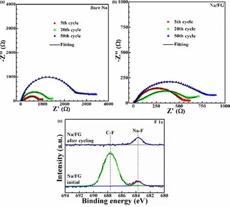
Figure 6. Nyquist plots of symmetric cells with a) bare Na and b) Na/FG electrodes at 0.5 mA cm-2 with a capacity of 1 mAh cm-2, and c) F 1s XPS of Na/FG electrode at the initial state and after 25 cycles at 0.5 mA cm-2 with 0.5 mAh cm-2 capacity.
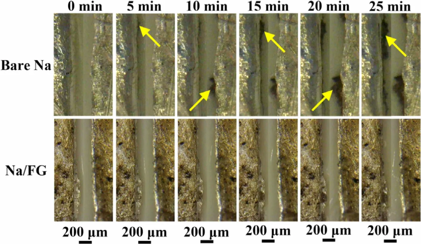
Figure 7. In situ optical microscopy images of Na deposition on bare Na and Na/FG electrodes during cycling at 1 mA cm-2 with switched current direction(every 5 min).
To identify the component change of the Na/FG electrode, X-ray photoelectron spectra (XPS) analyses were executed after 25 cycles at 0.5 mA cm-2with 0.5 mAh cm-2capacity.Figure S7 shows the XPS survey spectra of Na/FG electrode at the initial state and after cycling.The peaks of Na 1s,C 1s,and O 1s can be clearly observed,while the peak intensity of F 1s is weak because of the small amount of FG.From the F 1s spectra of Na/FG electrode(Figure 6c),we notice that a strong peak corresponding to C–F bonds can be detected for the initial electrode.The presence of a small peak at around 683.7 eV suggests that a small part of FG has taken part in the reaction with Na during the preparation of Na/FG to form NaF.[62]After 25 cycles,the peak intensity of the C–F bonds obviously decreases compared to that of the pristine electrode. At the same time, the peak intensity of NaF increases, indicating the transformation from FG to NaF. The result demonstrates that FG in Na/FG can react with Na to form NaF and graphene during cycling. A conclusion thus can be drawn that NaF and graphene become parts of the SEI layer on the surface of Na. The presence of NaF and graphene enables the formation of a robust and uniform SEI layer, which can realize high Naion conductivity, reduce side reactions between Na and liquid electrolyte, and suppress growth of Na dendrites. Thus, Na degradation can be effectively refrained and a lower surface resistance is achieved.
In situ optical microscopy observation was carried out to investigate Na dendrite growth on bare Na and Na/FG electrodes using a home-made transparent cell (Figure S8). The selected optical images of the Na deposition process on both electrodes during cycling at 1 mA cm-2were given in Figure 7. The time for each cycle was set at 10 min, including 5-min charge and 5-min discharge by switching the current direction, and the total observation time is 25 min. For bare Na, small-sized mound-like dendrites emerge on the left electrode after 5-min discharge (Figure 7a and Video S1). During the following 5-min charge process, dendrites start to form on the right electrode while the dendrites at the left side are still present. After the third half cycle, the leftside dendrites grow obviously. Of note is that the dendrites grow at the different positions of the two electrodes, indicating uneven Na plating and stripping. Na dendrites continue to growth and accumulate on both sides of the symmetric cell in the subsequent cycles. For the Na/FG electrode, as seen in Figure 7a and Video S2, no obvious dendrite growth was observed during the whole charge-discharge cycles, suggesting inhibition effect of FG on Na dendrite growth.
To investigate the effect of current density on the dendrite growth behavior on bare Na and Na/FG electrodes, a higher current density of 3 mA cm-2was applied for the in situ optical microscopy observations. For the practical applications of Na–CO2cells, the deliverable current is a critical indicator to achieve a required power density. As seen in Figure 8a and Video S3, unlike the mound-like dendrites at 1 mA cm-2, the dendrites on bare Na at 3 mA cm-2exhibit a feather-like shape and have a rapid growth speed. Once the current is applied, sodium dendrites continue to form and grow that even reach the counter electrode, causing the short circuit or local short circuit of the cell(Figure 8b). At the same time, some dendrites also undergo fracture during growth, leading to accompanied voltage fluctuation(Figure 8b). In contrast, for Na/FG, Na dendrites are nearly invisible even at this high current density (Figure 8a, Video S4). Accordingly,the voltage curve only shows a slight fluctuation without the dendrite growth (Figure 8c). The slight fluctuation of the voltage in Figure 8c may be due to the local short circuit by Na dendrites and the subsequent recovery with dissolution or fracture of the dendrites.
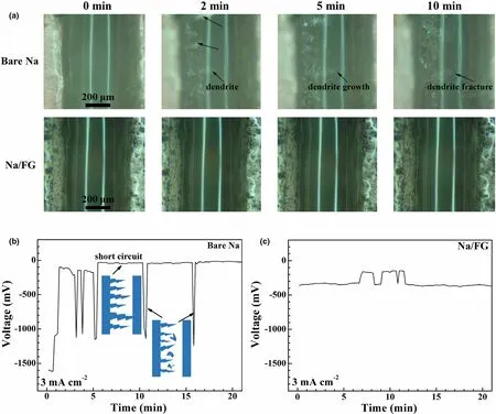
Figure 8. a) In situ optical microscopy images of Na deposition on bare Na and Na/FG electrodes during cycling at 3 mA cm-2, and the corresponding voltage profiles of b) bare Na and c) Na/FG.
To verify the thermodynamic feasibility of the aforementioned chemical reactions, DFT calculations were conducted to simulate Na adsorption onto FG. As seen in Figure 9a, 48 Na atoms are inserted into the FG lamella and we suppose they are divided equally on both sides of the lamella.FG is a derivative of graphene with fluorine atoms attached to carbon atoms, and it can be considered as the two-dimensional counterpart of graphite fluoride.[63]It is noteworthy that in the optimized structure, a separated graphene layer emerges, accompanied by all the F atoms binding with Na atoms. Meanwhile, the hybridization of carbon atoms changes from sp3to sp2due to the disruption of the C–F bonds.Moreover,the calculations in Figure 9b suggest that the reaction between Na and FG is spontaneous and the release energy with the adsorption of each Na atom is around 1.645 eV.Upon Na adsorption,charges transfer from Na to F,and in turn,the charges transferred from C to F decrease,which leads to weakened C–F bonds. This is the reason why F 1s XPS peak referring to Na–F bonds can be detected before cycling. The strong interactions between Na and F atoms in the FG lamella finally result in the complete disruption of C–F bonds after cycling,which is consistent with the fact that F 1s XPS peak of the C–F bonds for Na/FG disappears after cycling. In conclusion, the reaction Na + FG →NaF + graphene is thermodynamically feasible, and NaF as well as graphene function as the key to promote the electrochemical and mechanical stability of the Na/FG electrode.Note that although the above reaction will decrease the coulombic efficiency, the degree is sight since the FG content is low(~3%).

Figure 9. a) Model of Na adsorption onto FG and the optimized structure, b) thermodynamic calculation results of the proposed chemical reaction between Na and FG by DFT method,and c)general mechanism of Na plating/stripping behavior on bare Na and Na/FG.
On the basis of the above experimental analyses and theoretical calculations, we propose a general mechanism for Na plating/stripping on bare Na and Na/FG electrodes (Figure 9c). As for bare Na, an SEI layer on the surface of Na is built through the reaction between Na and electrolyte.However,the SEI layer is not stable enough to endure even Na plating during cycling, causing formation and growth of Na dendrites.In the subsequent stripping process,Na dendrites are inclined to dissolve gradually and detach from the surface of Na to become “dead Na,” which will cause capacity decline and electrode damage in the end.Simultaneously,the heterogeneous stripping of Na leads to rough surface and destruction of the SEI layer,followed by more side reactions between Na and electrolyte. With regard to Na/FG, the production of NaF and graphene drives the construction of a robust SEI layer with better mechanical stability and higher conductivity for Na-ion transport.During the Na plating/stripping process, the surface of Na/FG prefers to keep its evenness, which is favorable for Na dendrite inhibition and long cycle life of the Na/FG electrode and thereby excellent cycling stability of the Na–CO2full cells.
3. Conclusion
In summary, we fabricated a sodium composite anode composed of metallic Na and fluorinated graphene with a facile method inspired by the forging processing. The composite anode has a low resistance with effectively alleviated electrode degradation over a long time. Compared with bare Na, Na/FG electrode shows enhanced cycling stability with a low hysteresis for more than 1400 h at 0.5 mA cm-2current density and 1 mAh cm-2capacity. The Na/FG electrode can realize stable cycling for over 700 h even with a high areal capacity up to 5 mAh cm-2at a high current density as high as 5 mA cm-2. SEM and in situ optical microscopy observations confirm dendrite-free Na stripping/plating behavior of the Na/FG electrode. The excellent properties of Na/FG are ascribed to the robust NaF-rich/graphenereinforced SEI layer formed in situ during cycling. The formation of NaF was confirmed by both experimental observations and theoretical calculations. The SEI layer could facilitate Na-ion conductivity, block electron transfer,suppress Na dendrite growth, and inhibit reaction between Na and electrolyte. Na–CO2cell with the Na/FG anode shows a high full-discharge capacity and a long cycle life (391 cycles at 1000 mAh g-1). This work provides a practical strategy to design stable Na anodes for high-energy-density, long-life Na metal batteries.
4. Experimental Section
Na/FG composite anode processing: FG powder(≥99.998%, ~50% F content, XFNANO, Co., Ltd.) was dried at 80 °C in vacuum oven in advance. Na foil(99.9%, Sinopharm Chemical Reagent Co., Ltd.) was first melted at about 250 °C by an electric soldering iron in an Al2O3boat. The melt shrank into an ellipsoid and adsorbed the FG powder on the surface when it was rolling in the boat. After cooling, the Na/FG was mechanically hammered. The FG-adsorption and hammering steps were repeated until a uniform Na/FG composite was obtained. Afterward, the Na/FG sheet was punched into disks with a diameter of 1.2 cm. The mass proportion of FG in the composite anode is around 3 wt%. All the above operations were carried out in an Ar-filled glove box.
Material characterization: The phases in the electrodes were analyzed by X-ray diffraction (XRD) on a Rigaku D/Max-2550pc powder diffractometer equipped with Cu Kαradiation (λ = 1.541°A). The morphologies of the electrodes were observed by field emission scanning electron microscope (SEM)on an SU-8010 microscope (Hitachi, Japan). X-ray photoelectron spectra(XPS) of the electrodes were collected on a KRATOS AXIS SUPER-DLD spectrometer with monochromatic Al Kαradiation (hν = 1486.6 eV). In situ observation of Na plating/stripping was performed using a BETICALXTL microscope with home-made transparent cells which are airtight during testing.
Electrochemical measurements: Coin-type Na/FG–Na/FG (or Na–Na) half cells and Na/FG–CO2(or Na–CO2) full cells were assembled in the argonfilled glove box using glass-fiber membrane (Whatman) as the separators and 0.5 M NaCF3SO3in tetraethylene glycol dimethyl ether (TEGDME) as the electrolyte. For the Na–CO2full cells, the cathode side of the coin cells was drilled with several holes and the carbon cloth-supported δ-MnO2electrodes were used as the cathodes. The preparation procedure was described in detail in Supporting Information. The cathodes were dried in a vacuum oven at 80 °C overnight before cells assembly. Prior to the electrochemical measurements, the assembled cells were purged with pure CO2for 15 min and stayed at open-circuit voltage (OCV) for 5 h. The galvanostatic cycling of Na–CO2full cells was conducted on a Neware battery tester (Shenzhen,China) at 1.5–4.5 V (vs Na/Na+). The specific capacity (mAh g-1) and current density (mA g-1) were calculated based on the weight of MnO2. Electrochemical impedance spectroscopy (EIS) was measured on the VersaSTAT3 electrochemistry workstation by applying an AC signal of 5 mV amplitude in the frequency range of 10-2to 105Hz. The electrochemical measurements were all performed at 25 °C.
Theoretical methods: All the calculations were performed based on the density functional theory (DFT) using the generalized gradient approximation(GGA) within Perdew–Burke–Ernzerhof (PBE)[64]implemented in the Vienna ab-initio Simulation Package.[65]The projector augmented wave pseudo-potential method was applied to model ionic potentials.[66]Kinetic energy cutoff was set above 400 eV for calculations. The Monkhorst-Pack scheme k-points sampling method was adopted for the integration in the first Brillouin zone.[67]All the atoms were completely relaxed until the force on them was smaller than 0.02 eV°A-1. We used a 3 × 1 × 1 FG supercell (including 16 C and 16 F) to simulate the chair configuration of FG. The FG layer model was obtained from the bulk model of fluorinated graphite, and the layer was separated by a 20°A thick vacuum layer, for the purpose of avoiding the interactions between neighboring images.
Acknowledgements
Y.M.,X.C.and H.C.contributed equally to this work.This work was supported by the National Natural Science Foundation of China(No.51572238),Zhejiang Provincial Natural Science Foundation of China under Grant no. LY19E020013, and Hunan Provincial Science and Technology Major Project of China(2020GK1014).
Conflict of Interest
The authors declare no conflict of interest.
Supporting Information
Supporting Informationis available from the Wiley Online Library or from the author.
Keywords
composite anode, fluorinated graphene, Na dendrite, Na–CO2battery, NaFrich protecting layer
Received: January 7, 2021
Revised: March 5, 2021
Published online: March 20, 2021
[1] J. M. Matter, M. Stute, S. ′O. Snæbj¨ornsdottir, E. H. Oelkers, S. R. Gislason,E. S. Aradottir, B. Sigfusson, I. Gunnarsson, H. Sigurdardottir, E. Gunnlaugsson, G. Axelsson, H. A. Alfredsson, D. Wolff Boenisch, K. Mesfin, D.F. D. Taya, J. Hall, K. Dideriksen, W. S. Broecker, Science 2016, 352, 1312.
[2] X.P.Wu,I.Choudhuri,D.G.Truhlar,Energy Environ.Mater.2020,3,516.
[3] Y. X. Pan, Y. You, S. Xin, Y. T. Li, G. T. Fu, Z. M. Cui, Y. L. Men, F. F.Cao, S. H. Yu, J. B. Goodenough, J. Am. Chem. Soc. 2017, 139, 4123.
[4] Z. D. Dai, M. Usman, M. Hillestad, L. Y. Deng, Green. Energy Environ.2016, 1, 266.
[5] J. L. Qiao, Y. Y. Liu, F. Hong, J. J. Zhang, Chem. Soc. Rev. 2014, 43, 631.
[6] J. Schneider, H. F. Jia, J. T. Muckerman, E. Fujita, Chem. Soc. Rev. 2012,41, 2036.
[7] J. L. White, M. F. Baruch, J. E. Pander, Y. Hu, I. C. Fortmeyer, J. E. Park,T. Zhang, K. Liao, J. Gu, Y. Yan, T. W. Shaw, E. Abelev, A. B. Bocarsly,Chem. Rev. 2015, 115, 12888.
[8] C. D. Windle, R. N. Perutz, Coord. Chem. Rev. 2012, 256, 2562.
[9] S. Gao, Y. Lin, X. C. Jiao, Y. F. Sun, Q. Q. Luo, W. H. Zhang, D. Q. Li, J.L. Yang, Y. Xie, Nature 2016, 529, 68.
[10] D. Esrafilzadeh, A. Zavabeti, R. Jalili, P. Atkin, J. Choi, B. J. Carey, R.Brklja˘ca, A. P. O’Mullane, M. D. Dickey, D. L. Officer, D. R. MacFarlane,T. Daeneke, K. Kalantar Zadeh, Nat. Commun. 2019, 10, 865.
[11] D. Higgins, C. Hahn, C. X. Xiang, T. F. Jaramillo, A. Z. Weber, ACS Energy Lett. 2019, 4, 317.
[12] A. M. Appel, J. E. Bercaw, A. B. Bocarsly, H. Dobbek, D. L. DuBois, M.Dupuis,J.G.Ferry,E.Fujita,R.Hille,P.J.A.Kenis,C.A.Kerfeld,R.H.Morris,C.H.F.Peden,A.R.Portis,S.W.Ragsdale,T.B.Rauchfuss,J.N.H.Reek,L.C.Seefeldt,R.K.Thauer,G.L.Waldrop,Chem.Rev.2013,113,6621.
[13] C. T. Dinh, T. Burdyny, M. G. Kibria, A. Seifitokaldani, C. M. Gabardo, F.P. G. de Arquer, A. Kiani, J. P. Edwards, P. De Luna, O. S. Bushuyev, C.Q. Zou, R. Quintero Bermudez, Y. J. Pang, D. Sinton, E. H. Sargent,Science 2018, 360, 783.
[14] M. Schreier, L. Curvat, F. Giordano, L. Steier, A. Abate, S. M. Zakeeruddin, J. S. Luo, M. T. Mayer, M. Gr¨atzel, Nat. Commun. 2015, 6, 7326.
[15] J. Wei, Q. J. Ge, R. W. Yao, Z. Y. Wen, C. Y. Fang, L. S. Guo, H. Y. Xu, J.Sun, Nat. Commun. 2017, 8, 15174.
[16] Z. J. Xie, X. Zhang, Z. Zhang, Z. Zhou, Adv. Mater. 2017, 29, 1605891.
[17] K. Takechi, T. Shiga, T. Asaoka, Chem. Commun. 2011, 47, 3463.
[18] S. M. Xu, S. K. Das, L. A. Archer, RSC Adv. 2013, 3, 6656.
[19] Y.L.Liu,R.Wang,Y.C.Lyu,H.Li,L.Q.Chen,Energy Environ.Sci.2014,7,677.
[20] Y.Qiao,J.Yi,S.C.Wu,Y.Liu,S.X.Yang,P.He,H.S.Zhou,Joule2017,1,359.
[21] V. Palomares, P. Serras, I. Villaluenga, K. B. Hueso, J. Carretero Gonzalez,T. Rojo, Energy Environ. Sci. 2012, 5, 5884.
[22] F. S. Cai, Z. Hu, S. L. Chou, Adv. Sustainable Syst. 2018, 2, 1800060.
[23] X. W. Mu, H. Pan, P. He, H. S. Zhou, Adv. Mater. 2020, 32, 1903790.
[24] J. F. Xie, Z. Zhou, Y. B. Wang, Adv. Funct. Mater. 2020, 30, 1908285.
[25] X. F. Hu, J. C. Sun, Z. F. Li, Q. Zhao, C. C. Chen, J. Chen, Angew. Chem.Int. Ed. 2016, 55, 6482.
[26] E. Azaceta, L. Lutz, A. Grimaud, J. M. Vicent Luna, S. Hamad, L. Yate, G.Caba~nero, H. J. Grande, J. A. Anta, J. M. Tarascon, R. Tena Zaera, Chemsuschem 2017, 10, 1616.
[27] J. C. Sun, Y. Lu, H. Yang, M. Han, L. Y. Shao, J. Chen, Research 2018,2018, 6914626.
[28] F. Y. Cheng, J. Chen, Chem. Soc. Rev. 2012, 41, 2172.
[29] J. S. Lee, S. T. Kim, R. G. Cao, N. S. Choi, M. L. Liu, K. T. Lee, J. Cho,Adv. Energy Mater. 2011, 1, 34.
[30] D. I. Iermakova, R. Dugas, M. R. Palac′ın, A. Ponrouch, J. Electrochem.Soc. 2015, 162, A7060.
[31] R. G. Cao, K. Mishra, X. L. Li, J. F. Qian, M. H. Engelhard, M. E. Bowden, K. S.Han,K. T.Mueller,W. A.Henderson,J.G. Zhang, Nano Energy 2016,30,825.
[32] J. Song, G. Jeong, A. J. Lee, J. H. Park, H. Kim, Y. J. Kim, ACS Appl. Mater.Interfaces 2015, 7, 27206.
[33] Z. W. Seh, J. Sun, Y. M. Sun, Y. Cui, ACS Cent. Sci. 2015, 1, 449.
[34] P. Hartmann, C. L. Bender, J. Sann, A. K. D¨urr, M. Jansen, J. Janek, P.Adelhelm, Phys. Chem. Chem. Phys. 2013, 15, 11661.
[35] X. X. Bi, X. D. Ren, Z. J. Huang, M. Z. Yu, E. Kreidler, Y. Y. Wu, Chem.Commun. 2015, 51, 7665.
[36] N. Zhao, C. L. Li, X. X. Guo, Phys. Chem. Chem. Phys. 2014, 16, 15646.
[37] Y. G. Li, H. J. Dai, Chem. Soc. Rev. 2014, 43, 5257.
[38] K. Yan, Z. D. Lu, H. W. Lee, F. Xiong, P. C. Hsu, Y. Z. Li, J. Zhao, S. Chu,Y. Cui, Nat. Energy 2016, 1, 16010.
[39] W. Xu, J. L. Wang, F. Ding, X. L. Chen, E. Nasybulin, Y. H. Zhang, J. G.Zhang, Energy Environ. Sci. 2014, 7, 513.
[40] G. Y. Zheng, S. W. Lee, Z. Liang, H. W. Lee, K. Yan, H. B. Yao, H. T.Wang, W. Y. Li, S. Chu, Y. Cui, Nat. Nanotechnol. 2014, 9, 618.
[41] K. Yan, H. W. Lee, T. Gao, G. Y. Zheng, H. B. Yao, H. T. Wang, Z. D. Lu,Y. Zhou, Z. Liang, Z. F. Liu, S. Chu, Y. Cui, Nano Lett. 2014, 14, 6016.
[42] R. Zhang, N. W. Li, X. B. Cheng, Y. X. Yin, Q. Zhang, Y. G. Guo, Adv.Sci. 2017, 4, 1600445.
[43] Z.W.Seh,Y.M.Sun, Q.F.Zhang,Y.Cui,Chem.Soc.Rev.2016, 45,5605.
[44] A. X. Wang, X. F. Hu, H. Q. Tang, C. Y. Zhang, S. Liu, Y. W. Yang, Q. H.Yang, J. Y. Luo, Angew. Chem. Int. Ed. 2017, 56, 11921.
[45] Y. Zhao, L. V. Goncharova, A. Lushington, Q. Sun, H. Yadegari, B. Q.Wang, W. Xiao, R. Y. Li, X. L. Sun, Adv. Mater. 2017, 29, 1606663.
[46] H. Wang, C. L. Wang, E. Matios, W. Y. Li, Nano Lett. 2017, 17, 6808.
[47] K.Kanamura,S.Shiraishi,Z.Takehara,J.Electrochem.Soc.1996,143,2187.
[48] S. Komaba, T. Ishikawa, N. Yabuuchi, W. Murata, A. Ito, Y. Ohsawa,ACS Appl. Mater. Interfaces 2011, 3, 4165.
[49] S. Choudhury, L. A. Archer, Adv. Electron. Mater. 2016, 2, 1500246.
[50] X. Q. Zhang, X. B. Cheng, X. Chen, C. Yan, Q. Zhang, Adv. Funct. Mater.2017, 27, 1605989.
[51] J. M. Zheng, S. R. Chen, W. G. Zhao, J. H. Song, M. H. Engelhard, J. G.Zhang, ACS Energy Lett. 2018, 3, 315.
[52] X. L. Fan, L. Chen, X. Ji, T. Deng, S. Hou, J. Chen, J. Zheng, F. Wang, J. J.Jiang, K. Xu, C. S. Wang, Chem 2018, 4, 174.
[53] L. M. Suo, W. J. Xue, M. Gobet, S. G. Greenbaum, C. Wang, Y. M. Chen,W. L. Yang, Y. X. Li, J. Li, Proc. Natl. Acad. Sci. USA 2018, 115, 1156.
[54] Y. Yamada, K. Furukawa, K. Sodeyama, K. Kikuchi, M. Yaegashi, Y.Tateyama, A. Yamada, J. Am. Chem. Soc. 2014, 136, 5039.
[55] L. M. Suo, O. Borodin, T. Gao, M. Olguin, J. Ho, X. L. Fan, C. Luo, C. S.Wang, K. Xu, Science 2015, 350, 938.
[56] L. M. Suo, O. Borodin, Y. S. Wang, X. H. Rong, W. Sun, X. L. Fan, S. Y.Xu, M. A. Schroeder, A. V. Cresce, F. Wang, C. Y. Yang, Y. S. Hu, K. Xu,C. S. Wang, Adv. Energy Mater. 2017, 7, 1701189.
[57] J. H. Wang, Y. Yamada, K. Sodeyama, E. Watanabe, K. Takada, Y.Tateyama, A. Yamada, Nat. Energy 2018, 3, 22.
[58] K. Doi, Y. Yamada, M. Okoshi, J. Ono, C. P. Chou, H. Nakai, A. Yamada,Angew. Chem. Int. Ed. 2019, 58, 8024.
[59] X. P. Zhang, Y. N. Li, Y. Y. Sun, T. Zhang, Angew. Chem. Int. Ed. 2019,58, 18394.
[60] X. H. Zhao, Z. Sun, Z. G. Yao, Z. H. Cui, J. C. Wang, T. Zhang, J. Mater.Chem. A 2019, 7, 18237.
[61] C. F. Xu, K. W. Zhang, D. Zhang, S. L. Chang, F. Liang, P. F. Yan, Y. C.Yao, T. Qu, J. Zhan, W. H. Ma, B. Yang, Y. N. Dai, X. L. Sun, Nano Energy 2020, 68, 104318.
[62] Y. Liu, Y. C. Cai, Q. Zhang, L. J. Liu, Z. Q. Niu, J. Chen, Chem. Sci. 2019,10, 4306.
[63] R. A. Nair, W. C. Ren, R. Jalil, I. Riaz, V. G. Kravets, L. Britnell, P. Blake, F.Schedin, A. S. Mayorov, S. J. Yuan, M. I. Katsnelson, H. M. Cheng, W.Strupinski, L. G. Bulusheva, A. V. Okotrub, I. V. Grigorieva, A. N. Grigorenko, K. S. Novoselov, A. K. Geim, Small 2010, 6, 2877.
[64] J. P. Perdew, K. Burke, M. Ernzerhof, Phys. Rev. Lett. 1996, 77, 3865.
[65] G. Kresse, J. Furthm¨uller, Phys. Rev. B 1996, 54, 11169.
[66] P. E. Bl¨ochl, Phys. Rev. B 1994, 50, 17953.
[67] H. J. Monkhorst, J. D. Pack, Phys. Rev. B 1976, 13, 5188.
 Energy & Environmental Materials2022年2期
- Energy & Environmental Materials的其它文章
- Progress of Pb-Sn Mixed Perovskites for Photovoltaics:A Review
- Development Strategies in Transition Metal Borides for Electrochemical Water Splitting
- Polymer-/Ceramic-based Dielectric Composites for Energy Storage and Conversion
- Controllable Construction of Bifunctional CoxP@N,P-Doped Carbon Electrocatalysts for Rechargeable Zinc–Air Batteries
- Unveiling the Underlying Mechanism of Transition Metal Atoms Anchored Square Tetracyanoquinodimethane Monolayers as Electrocatalysts for N2 Fixation
- Rational Design of High-Performance Bilayer Solar Evaporator by Using Waste Polyester-Derived Porous Carbon-Coated Wood