
Activating Inert Sites in Cobalt Silicate Hydroxides for Oxygen Evolution through Atomically Doping
2022-07-04 09:13JiexinZhuLixueXiaWenxuanYangRuohanYuWeiZhangWenLuoYuhangDaiWeiWeiLiangZhouYanZhaoandLiqiangMai
Energy & Environmental Materials 2022年2期
Jiexin Zhu, Lixue Xia, Wenxuan Yang, Ruohan Yu, Wei Zhang, Wen Luo, Yuhang Dai,Wei Wei, Liang Zhou , Yan Zhao* , and Liqiang Mai*
1. Introduction
Water splitting includes two half-reactions, hydrogen evolution reaction(HER)and oxygen evolution reaction(OER),in which the OER is regarded as the bottleneck for its sluggish kinetics.[1–7]An efficient electrocatalyst is crucial to accelerate the reaction rate. In spite of superior performance achieved by precious metal-based catalysts, their massive applications are unpractical because of the scarcity.[8–11]Non-precious metal catalysts, such as perovskite,[12–15]spinel,[16–18]and hydroxide[19–22]provide new opportunities for OER, among which the NiFe(oxy)hydroxide[21]has been regarded as the benchmark catalysts in alkaline electrolyte.Metal silicate hydroxides,an emerging family of earth-abundant twodimensional materials which share a similar layered structure with oxyhydroxides, have been considered as competitive electrocatalysts toward OER.[23–27]The unique [SiO4] tetrahedron layer introduces the formation of an additional hydrogen bond to stabilize OOH*intermediate which makes silicate hydroxides an excellent OER performance.
However, metal silicate hydroxides usually exhibit limited active sites owing to the poor electron transfer ability. Like oxyhydroxides,introducing hetero-metal element in metal silicate hydroxides may effectively enhance catalytic activity. Qiu et al. reported a synergetic coaxial nanocable structure with excellent OER activity by growing Ni-Co silicate hydroxide nanosheets on multi-walled carbon nanotubes.[23]Kim et al.[26]introduced a Co-Fe binary silicate hydroxide with additional active sites by disturbing the local environment of oxygen and the optimal sample with 40 at.% Fe delivered an overpotential of 329 mV.Morphology and crystal structure have been considered as the origin of the enhanced catalytic activity of silicate hydroxides in these studies. However, electrocatalysis usually involves the adsorption of reactants to the surface of catalysts and the electron transfer between catalysts and reactants.[28–32]It remains unclear how hetero-metal doping modifies the electronic structure of metal silicate hydroxides and alters the adsorption behavior. Besides, it is also unknown that what kind of doping state(either in solid solution or phase segregated islands)is beneficial for the activity,and what is the optimal doping amount.Answering the questions above is of great significane to the development of metal silicate hydroxide-based OER electrocatalysts.
Here,we report an atomically doping strategy to boost the OER performance of metal silicate hydroxides using cobalt silicate hydroxide nanosheets(CSHNs)as a paradigm.Different amounts of Fe have been doped into the CSHNs,and at an appropriate doping amount(6 at.%),the doped Fe can be stabilized in a solid-solution state with homogeneous dispersion. Synchrotron study and theoretical calculations reveal that the incorporation of Fe introduces a slight electron transfer from Fe to Co,resulting in an optimal Co 3d and Fe 3d electronic occupation and adsorption capacity to oxygen intermediates. Such atomically dispersed Fe-doping activates Co inert sites and endows the Fe-doped CSHNs(FCSHNs) an optimal overpotential of 293 mV at 10 mA cm-2and a Tafel slope of 47.2 mV dec-1. Further computation reveals that the electronic interaction in the Co-O-Fe units improves the absorption capacity to oxygen intermediate and reduces the OER overpotential.
2. Results and Discussion
2.1. Characterization of CSHNs and FCSHNs
The CSHNs and FCSHNs are synthesized directly by a one-step hydrothermal method,and the samples prepared at Fe/Co feed ratios of 0, 0.03, 0.06, and 0.10, are named as CSHNs, FCSHNs-3, FCSHNs-6,and FCSHNs-10, respectively. The Fe/Co atomic ratios are determined by inductively coupled plasma-optical emission spectrometer (ICPOES), and the values agree well with the Fe/Co feeding ratios (Figure S1). All the CSHNs and FCSHNs samples show an ultrathin nanosheet morphology with negligible difference (Figure 1a and Figure S2). The nanosheets range in width from 50 to 100 nm and they interconnect with each other. A typical high-angle annular dark-field scanning transmission electron microscopy (HAADF-STEM) image and the corresponding energy dispersive X-ray (EDX) elemental mappings manifest that the Fe was uniformly distributed in the FCSHNs-6 (Figure S3). To further confirm the elemental distributions, STEM-electron energy-loss spectroscopy (STEM-EELS) was conducted. The EELS element mappings and Fe L-edge and Co L-edge spectra together verify the homogeneous doping of Fe in the FCSHNs-6 (Figure 1b–d). Specifically, the three line-scan spectra manifest low and semblable Fe L-edge intensities, demonstrating the highly atomistic dispersion of Fe. Based on the above characterizations,a cobalt silicate hydroxide structure with atomic Fe doping is proposed (Figure 1e). Previous reports revealed the low crystallinity of metal silicate hydroxides.[24]Similarly, the CSHNs and FCSHNs show relatively low crystallinity as confirmed by X-ray diffraction (XRD, Figure S4). High-resolution TEM (HRTEM,Figure S5a) and selected area electron diffraction (SAED, Figure S5b)demonstrate that the FCSHNs-6 possesses local ordering but lacks longrange ordering. The Fourier-transform infrared (FT-IR, Figure S6)spectra provide evidence on the local structure of CSHNs and FCSHNs.[33–34]Atomic force microscopy (AFM, Figure S7) images show that the thickness of CSHNs and FCSHNs ranges from a few nanometers to dozens of nanometers.From HAADF-STEM images(Figure S8), both single-layer nanosheets (indicated by red arrows) and multi-layer nanosheets can be found. Even for the multi-layer nanosheets,their thickness is generally<10 nm.
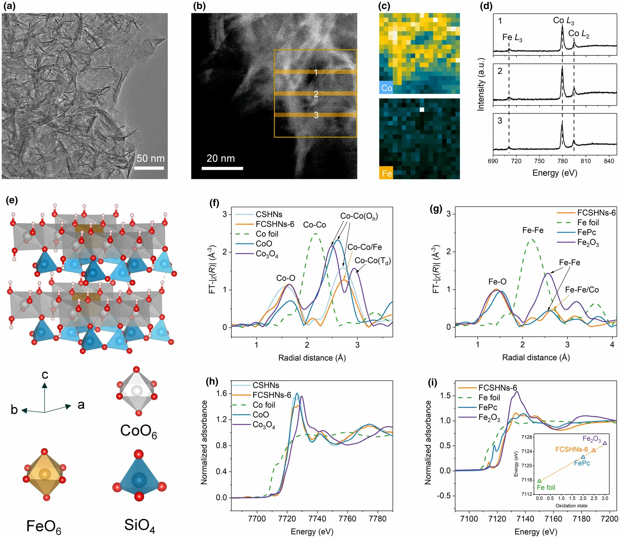
Figure 1. a) TEM image of FCSHNs-6; b) HAADF-STEM image of FCSHNs-6; c) EELS elemental mappings of Co and Fe corresponding to the rectangular area in b; d) Fe L-edge and Co L-edge EELS spectra record from b (the numbers from 1 to 3 in d correspond to the numbers from 1 to 3 in b); e) crystal structure of FCSHNs-6; f) FT k3χ(R) Co K-edge EXAFS and h) normalized Co K-edge XANES spectra for CSHNs, FCSHNs-6, Co foil, CoO, and Co3O4; g) FT k3χ(R) Fe K-edge EXAFS and i) normalized Fe K-edge XANES spectra for FCSHNs-6, Fe foil, FePc, and Fe2O3 (inset in i: fitted oxidation states of Fe).

Figure 2. a) Temperature dependent magnetization under H = 2 kOe and the temperature dependent inverse susceptibilities of the CSHNs and FCSHNs. The solid lines are the fitting results by using the Curie–Weiss law:χ = C/(T-Θ)above 150 K(C,Curie constant;Θ,Curie–Weiss temperature);b)Co L-edge;c)Fe Ledge XANES spectra of CSHNs,FCSHNs-3,FCSHNs-6,and FCSHNs-10;and d)charge density difference of CSHNs,FCSHNs-3,FCSHNs-6,and FCSHNs-10.The red color means high charge density difference,while blue means low charge density difference.
To give an in-depth understanding of the coordination and electronic structure of CSHNs and FCSHNs,X-ray absorption fine structure spectroscopy (XAFS), temperature-dependent magnetic susceptibility(M-T), and X-ray photoelectron spectroscopy (XPS) were performed.As displayed in Figure S9, the Co K-edge extended XAFS (EXAFS) k2χ(k) oscillation curves of CSHNs and FCSHNs-6 show an approximate oscillation amplitude, implying the analogical coordination environment of Co. The Fourier-transform EXAFS (FT-EXAFS) curves for CSHNs and FCSHNs-6 show noticeable Co-O(1.57°A for CSHNs and 1.64°A for FCSHNs-6) and Co-Co/Fe (2.73°A) coordination (Figure 1f). The peaks at 1.41°A and 2.58°A for FCSHNs-6 in Figure 1g can be assigned to the first shell Fe-O and the nearest Fe-Co/Fe coordination, respectively. Noteworthy, the peak intensity of Fe-Co/Fe coordination is much weaker than that of Co-Co/Fe, verifying the existence of atomically dispersed Fe atoms in FCSHNs-6. The X-ray absorption near-edge structure (XANES) curves of both CSHNs and FCSHNs display a white line intensity lower than CoO (Figure 1h),indicating that the average valence states of Co for CSHNs and FCSHNs-6 are lower than +2, and the FCSHNs-6 possesses the lowest valence state for Co. As shown in Figure 1i, the adsorption edge of FCSHNs-6 shifts toward higher energy relative to the FePc, corresponding to the increase of Fe valence state. By fitting the adsorption edge, the average oxidation state of Fe in FCSHNs-6 is 2.48 and it suggests that the Fe can act as an electron donor.

Figure 3. a) CV curves; b) Comparison of the overpotential at 10 mA cm-2 and TOF at η = 300 mV of different catalysts; c) Tafel plots of different catalysts derived from CV;, d) Δj = ja-jc at 1.175 V versus RHE as a function of the scan rate to evaluate Cdl; e) Long-term stability of CSHNs and FCSHNs-6 at j = 10 mA cm-2 for 24 h; and f) Comparison of overpotential at different current densities for various bimetal catalysts.
Figure 2a shows typical susceptibilities obey the paramagnetic Curie–Weiss law above 150 K and the fitting results (Figure S10) of effective magnetic moment(μeff)unravel the number of unfilled d orbitals.[35]It is indicated that the FCSHNs-6 contains the most unpaired electrons while CSHNs involve the least, which may be caused by the electronic interaction between Co and Fe species. More in-depth electron transfer analysis can be obtained through XPS and metal L-edge XANES. Compared to the CSHNs, the Co 2p binding energies of FCSHNs-3 and FCSHNs-6 are shifted to lower values, while that of FCSHNs-10 is shifted to a higher value (Figure S11). The Co L-edge XANES (Figure 2b) illustrates that the intensity reduces with the doping up to 6 at.%, and increases for FCSHNs-10. The Fe L-edge XANES(Figure 2c) spectra reveal the emergence of unfilled t2gorbitals for FCSHNs-3 and FCSHNs-6. From the XPS and XANES results, one can know that the electron transfers from Fe t2gorbitals to Co egorbitals in FCSHNs-3 and FCSHNs-6, while the electron transfer process is reversed for FCSHNs-10.[36]Moreover, the charge density difference(Figure 2d) was performed using density functional theory (DFT) calculations and it is revealed that the fluxion orientation of electrons changes with Fe doping. For FCSHNs-3 and FCSHNs-6, the Fe atoms exhibit a decreased charge density, meaning that part of the electrons are relayed from Fe to Co. However, when the doping content is increased to 10 at.%,the distribution becomes compact,suggesting the Fe atoms are converted into electron acceptors.The DFT calculations on charge density agree well with the XPS and XANES results. Combining the spectral and computational results,it is speculated that the Fe exists in the form of atomically doping in FCSHNs-3 and FCSHNs-6. The computational crystal model (Figure S12) indicates the metal-oxygen bond length is shortened in FCSHNs-3 and FCSHNs-6, and thus improves the electronic interaction,which matches well with the variation of Co–O coordination in Co K-edge EXAFS. These observations suggest that low-dose doping is more beneficial to increasing the charge density of Co species.
2.2. Electrocatalytic Properties of CSHNs and FCSHNs Towards OER
The OER activity was studied in 1.0 M KOH using rotating disk electrode (RDE) without IR correction. The trace iron impurities in electrolyte were removed by suspending the Ni(OH)2powder. The cyclic voltammetry(CV)profiles in Figure 3a show that all the catalysts exhibit competitive OER performance. The CSHNs require an overpotential of 367 mV for reaching a specific current density of 10 mA cm-2,which decrease to 339 mV for FCSHNs-3,293 mV for FCSHNs-6,and 335 mV for FCSHNs-10(Figure 3b).The FCSHNs-6 shows the lowest overpotential and even surpasses some NiFe oxyhydroxide catalysts,[37]meaning that the electron transfer plays a key role in facilitating the adsorption capacity to intermediate. It should be noted that the redox peaks which are often observed for transition metal hydroxides and oxyhydroxides in the interval between 1.3 and 1.4 V are not detected.[20,38]This phenomenon implies that there is no change in structure and chemical state for metal silicate hydroxide during electrocatalysis. The turnover frequency (TOF,Figure 3b, and Figure S13) of FCSHNs-6 at η = 300 mV (0.033 s-1) is over three times as much as CSHNs (0.0095 s-1). Figure 3c illustrates that the Tafel slope of FCSHNs-6 is 47.2 mV dec-1, lower than 75.1 mV dec-1for CSHNs, 66.0 mV dec-1for FCSHNs-3, and 66.2 mV dec-1for FCSHNs-10. The comparatively high TOF and low Tafel slope of FCSHNs-6 manifest that 6 at.% of the atomically dispersed Fe doping can bestow the optimal electronic structure for oxygen adsorption. According to previous reports, optimal OER performances can be achieved when the number of electrons in egorbital of a transition metal is about 1.2 for perovskites[12–13]and spinels.[39]Therefore,it is reasonable to postulate that the optimal OER activity of FCSHNs-6 is stem from the transfer of oligarchic electrons from the Fe t2gorbital to the Co egorbital, resulting in the increase of electrons on the Co egorbital to around 1.2.

Figure 4. Partial density of states of Co 3d-band a), Co 3d eg-band b), and Fe 3d t2g-band c) of the catalysts; d) Schematic representation of the electronic coupling between Co and Fe; e) The free energy diagram of OER on the CSHNs and FCSHNs-6; f) The structure for the *OOH formation step of CSHNs and FCSHNs-6. The ball represents different elements. Silver: Co; Brown: Fe; Blue: Si; Green: Oxygen from absorbed intermediates; Red: Oxygen; Pink: H.
CV tests(Figure S14)at various scan rates were used to estimate the electrochemical surface areas (ECSA). The FCSHNs-6 provides a larger double-layer capacitance (Cdl) than the other catalysts (Figure 3d),which offers the information regarding more active sites induced by the Fe incorporation. The internal charge-transfer resistance (Rct) was determined using electrochemical impedance spectroscopy (EIS) at the overpotential of 300 mV (Figure S15). The Rctvalues are 37.3, 13.2,3.95, and 6.37 Ω for the CSHNs-0, FCSHNs-3, FCSHNs-6, and FCSHNs-10, respectively. It is speculated that partial relatively inert Co sites are activated by the nearest neighbor Fe, accounting for the increase of active sites and remarkable charge-transfer ability of FCSHNs-6,and thus the excellent intrinsic OER activity.We then study the catalytic stability,both the CSHNs and FCSHNs-6 exhibit high activity after 24 h of testing, proving the excellent stability of the samples(Figure 3e). Compared with earlier reports on bimetallic oxide and hydroxide catalysts,the CSHNs and FCSHNs catalysts show competitive OER performance in terms of overpotential and Tafel slope (Figure 3f and Table S1).
2.3. Correlation Between the Electronic Structure and OER activity
We further investigated the density of states (DOS, Figure 4a and Figure S16) to furnish more insight into the electronic structure of FCSHNs catalysts.Obviously,the FCSHNs-3 and FCSHNs-6 carry lower DOS of energy,implying an enhanced ability to accept electrons.Meanwhile, the FCSHNs-6 has the highest states in the region close to the Fermi level (Figure S17). Additionally, in the region above the Fermi level,the states of Co 3d egorbital decrease until a Fe doping amount of 6 at.% and then increase on further doping (Figure 4b). The states of Fe 3d t2gorbital show the unfilled state for FCSHNs-3 and FCSHNs-6,and disappear as the further increase of dopant (Figure 4c). The variation of states mean that the electron transfer occurs mainly between Co egorbitals and Fe t2gorbitals.
The Co-O-Co and Co-O-Fe unit was applied to analyze the electronic interaction between Co and Fe in FCSHNs (Figure 4d).Specifically, electron-electron repulsion is the dominated interaction between Co and bridging O because of the fully occupied Co t2gorbitals. Moreover, the behavior of π-donation is absent and the π*-antibonding orbitals are fully occupied, which weaken the bond strength of Co-O. In contrast, the valence electronic configuration of Fe2.48+in FCSHNs-6 is 3d5.48, meaning that there are unpaired electrons in Fe t2gorbitals. This property will trigger the π-donation effect and decrease the number of electrons in π*-antibonding orbitals, which enhance the Fe-O covalency and the structural stability. For FCSHNs-3 and FCSHNs-10, the more electrons in Fe t2gorbitals impair the Fe-O bond and thus weaken the OER performance. The reaction pathways and the corresponding Gibbs free energy were calculated to evaluate OER activity. As displayed in Figure 4e, both the CSHNs and FCSHNs undergo a typical four-electron OER reaction. Because of the enhanced Fe-O covalency, the rate-determining step for FCSHNs-6 is the formation of *OO and O2desorption with a ΔG of 0.38 eV, while that of CSHNs is the formation of *OOH with a ΔG of 0.82 eV as the attenuated Co-O covalency. The structural model for each step is plotted in Figures S18 and S19. Noted that in the step of *OOH formation (Figure 4f), there is an additional hydrogen bond between the H of *OOH and the terminal O site for FCSHNs-6,indicating that the FCSHNs-6 has a strong capacity to stabilize the*OOH intermediate.Based on the above discussions,it can be concluded that the introduction of Co-O-Fe units improves the absorption capacity to oxygen intermediate.
To investigate the structural transformation, we conducted the insitu Raman test for CSHNs and FCSHNs-6. As shown in Figure S20,the samples show the distinct bridge symmetric stretching vibrations of Si–O–Si in the range of 400 – 800 cm–1.[40–41]Specifically, the peak around 690 cm–1in FCSHNs-6 display a broader peak than that of CSHNs, which may be ascribed to the existence of silica tetrahedron bonded with Fe–O. At the potential from 1.1 to 1.6 V, the peaks of vs(Si–O–Si) in CSHNs and FCSHNs-6 all show negligible change in terms of width and strength,meaning that the metal silicate hydroxides can maintain the structural stability under OER conditions. Moreover,the TEM images shown in Figure S21 of CSHNs and FCSHNs-6 after OER test also show negligible change in morphology, and the aggravated aggregation of nanosheets may be caused by the additional nafion binder.The corresponding EDS mappings of FCSHNs-6 exhibit the uniform Fe doping in Co units,indicating that no leaching behavior of Fe proceeds during OER test.
3. Conclusion
In conclusion, a series of Fe-doped cobalt silicate hydroxide has been designed for OER, and the effects on Fe-doping have been systematically studied. By doping an optimal Fe amount (6 at.%), the obtained FCSHNs-6 features an atomically Fe dispersion and significantly enhanced OER activity compared to CSHNs. With partial electrons transferred from Fe to Co, relatively inert Co sites are activated and bears an optimal electronic occupation for the adsorption of oxygen intermediate. Theoretical calculations reveal that the introduction of Co-O-Fe units enhances the M-O covalency and the ability to stabilize *OOH intermediate for FCSHNs-6 and changes the ratedetermining step. Obviously, the electronic interaction introduced by doping atomically dispersed Fe plays a significant role in boosting the OER performance. This work provides insights into engineering electronic structure and tailoring the local coordination environments of metal silicate hydroxide electrocatalysts for OER. This concept can be extended to the exploration of high-performance bimetallic or trimetallic silicate hydroxide electrocatalysts.
Acknowledgements
J.Z., L.X., and W.Y. contributed equally to this work. This work was supported by the National Key Research and Development Program of China(2020YFA0715004),National Natural Science Foundation of China(51832004), Foshan Xianhu Laboratory of the Advanced Energy Science and Technology Guangdong Laboratory(XHT2020-003), the Fundamental Research Funds for the Central Universities(195101005, 2020-CL-A1-28, 2020Ⅲ004GX). We thank the BL14W1 station in Shanghai Synchrotron Radiation Facility (SSRF), and 1W1B station in Beijing Synchrotron Radiation Facility (BSRF) for XAFS measurement. This S/TEM work was performed at the Nanostructure Research Center(NRC),which is supported by the State Key Laboratory of Advanced Technology for Materials Synthesis and Processing,and the State Key Laboratory of Silicate Materials for Architectures(all the laboratories are at Wuhan University of Technology).
Conflict of Interest
The authors declare no conflict of interest.
Supporting Information
Supporting Informationis available from the Wiley Online Library or from the author.
Keywords
atomically doping, electrochemistry, electron transfer, metal silicate hydroxides, oxygen evolution
Received: April 23, 2021
Revised: May 8, 2021
Published online: May 12, 2021
[1] S. Zhao, Y. Wang, J. Dong, C.-T. He, H. Yin, P. An, K. Zhao, X. Zhang, C.Gao, L. Zhang, J. Lv, J. Wang, J. Zhang, A. M. Khattak, N. A. Khan, Z.Wei, J. Zhang, S. Liu, H. Zhao, Z. Tang, Nat. Energy 2016, 1, 1.
[2] X. Zheng, B. Zhang, P. De Luna, Y. Liang, R. Comin, O. Voznyy, L. Han, F.P. G. de Arquer, M. Liu, C. T. Dinh, T. Regier, J. J. Dynes, S. He, H. L. Xin,H.Peng,D.Prendergast,X.Du,E.H.Sargent,Nat.Chem.2018,10,149.
[3] S. Anantharaj, S. R. Ede, K. Karthick, S. S. Sankar, K. Sangeetha, P. E.Karthik, S. Kundu, Energ. Environ. Sci. 2018, 11, 744.
[4] S. Liu, H. Cheng, K. Xu, H. Ding, J. Zhou, B. Liu, W. Chu, C. Wu, Y. Xie,ACS Energy Lett. 2018, 4, 423.
[5] Z. Zhuang, Y. Li, J. Huang, Z. Li, K. Zhao, Y. Zhao, L. Xu, L. Zhou, L. V.Moskaleva, L. Mai, Sci. Bull. 2019, 64, 617.
[6] C. Zhao, J. Liu, J. Wang, D. Ren, J. Yu, X. Chen, B. Li, Q. Zhang, Adv.Mater. 2021, 15, 2008606.
[7] Y. Yao, Z. Zhang, L. Jiao, Energ. Environ. Mater. 2021. https://doi.org/10.1002/eem2.12198
[8] R. R. Rao, M. J. Kolb, N. B. Halck, A. F. Pedersen, A. Mehta, H. You, K.A. Stoerzinger, Z. Feng, H. A. Hansen, H. Zhou, L. Giordano, J. Rossmeisl,T. Vegge, I. Chorkendorff, I. E. L. Stephens, Y. Shao-Horn, Energ. Environ.Sci. 2017, 10, 2626.
[9] Y. Lee, J. Suntivich, K. J. May, E. E. Perry, Y. Shao-Horn, J. Phys. Chem.Lett. 2012, 3, 399.
[10] Y. Yao, S. Hu, W. Chen, Z.-Q. Huang, W. Wei, T. Yao, R. Liu, K. Zang, X.Wang, G. Wu, W. Yuan, T. Yuan, B. Zhu, W. Liu, Z. Li, D. He, Z. Xue, Y.Wang, X. Zheng, J. Dong, C. Chang, Y. Chen, X. Hong, J. Luo, S. Wei, W.Li, P. Strasser, Y. Wu, Y. Li, Nat. Catal. 2019, 2, 304.
[11] B. Huang, Y. Ma, Z. Xiong, Z. Xiao, P. Wu, P. Jiang, M. Liang, Energ. Environ. Mater. 2020. https://doi.org/10.1002/eem2.12150
[12] J. Suntivich, K. J. May, H. A. Gasteiger, J. B. Goodenough, Y. Shao-Horn,Science 2011, 334, 1383.
[13] Y. Tong, Y. Guo, P. Chen, H. Liu, M. Zhang, L. Zhang, W. Yan, W. Chu,C. Wu, Y. Xie, Chem 2017, 3, 812.
[14] J. Yu, R. Ran, Y. Zhong, W. Zhou, M. Ni, Z. Shao, Energ. Environ. Mater.2020,3,121.
[15] T. Shen, L. Spillane, J. Vavra, T. H. M. Pham, J. Peng, Y. Shao-Horn, V.Tileli, J. Am. Chem. Soc. 2020, 142, 15876.
[16] Y. Zhou, S. Sun, J. Song, S. Xi, B. Chen, Y. Du, A. C. Fisher, F. Cheng, X.Wang, H. Zhang, Z. J. Xu, Adv. Mater. 2018, 30, 1802912.
[17] T. Wu, S. Sun, J. Song, S. Xi, Y. Du, C. Bo, W. A. Sasangka, H. Liao, C. L.Gan, G. Scherer, L. Zeng, H. Wang, H. Li, A. Grimaud, Z. J. Xu, Nat.Catal. 2019, 2, 763.
[18] X. Zhao, Y. Huang, C. Dong, C. Xie, Z. Liu, S. Du, W. Chen, D. Yan, L.Tao, Z. Shu, G. Zhang, H. Duan, Y. Wang, Y. Zou, R. Chen, S. Wang, J.Am. Chem. Soc. 2020, 142, 12097.
[19] Z.-F. Huang, J. Song, Y. Du, S. Xi, S. Dou, J. M. V. Nsanzimana, C. Wang,Z. J. Xu, X. Wang, Nat. Energy 2019, 4, 329.
[20] D. Y. Chung, P. P. Lopes, P. F. B. D. Martins, H. He, T. Kawaguchi, P.Zapol, H. You, D. Tripkovic, D. Strmcnik, Y. Zhu, S. Seifert, S. Lee, V. R.Stamenkovic, N. Markovic, Nat. Energy 2020, 5, 222.
[21] M. S. Burke, L. J. Enman, A. S. Batchellor, S. Zou, S. W. Boettcher, Chem.Mater. 2015, 27, 7549.
[22] C. Zhao, B. Li, M. Zhao, J. Liu, L. Zhao, X. Chen, Q. Zhang, Energ. Environ. Sci. 2020, 13, 1711.
[23] C. Qiu, J. Jiang, L. Ai, A. C. S. Appl, Mater. Inter. 2016, 8, 945.
[24] J. S. Kim, I. Park, E. S. Jeong, K. Jin, W. M. Seong, G. Yoon, H. Kim, B.Kim, K. T. Nam, K. Kang, Adv. Mater. 2017, 29, 1606893.
[25] C. Qiu, L. Ai, J. Jiang, A. C. S. Sustain, Chem. Eng. 2018, 6, 4492.
[26] B. Kim, J. S. Kim, H. Kim, I. Park, W. M. Seong, K. Kang, J. Mater. Chem.A 2019, 7, 18380.
[27] J. Zhu, S. Li, Z. Zhuang, S. Gao, X. Hong, X. Pan, R. Yu, L. Zhou, L. V.Moskaleva, L. Mai, Energ. Environ. Mater. 2020. https://doi.org/10.1002/eem2.12155
[28] S. Zhou, X. Miao, X. Zhao, C. Ma, Y. Qiu, Z. Hu, J. Zhao, L. Shi, J. Zeng,Nat. Commun. 2016, 7, 11510.
[29] J. O. M. Bockris, T. Otagawa, J. Electrochem. Soc. 1984, 131, 290.
[30] J. Rossmeisl, A. Logadottir, J. K. Nørskov, Chem. Phys. 2005, 319, 178.
[31] J. Rossmeisl, Z. W. Qu, H. Zhu, G. J. Kroes, J. K. Nørskov, J. Electroanal.Chem. 2007, 607, 83.
[32] Z. Wang, M. Jin, L. Zhang, A. Wang, J. Feng, J. Energy Chem. 2021, 53,260.
[33] R. Trujillano, J.-F. Lambert, C. Louis, J. Phys. Chem. C 2008, 112, 18551.
[34] M. A. Melo Jr, C. Airoldi, Dalton T. 2010, 39, 10217.
[35] Z. Li, Z. Zhuang, F. Lv, H. Zhu, L. Zhou, M. Luo, J. Zhu, Z. Lang, S. Feng,W. Chen, L. Mai, S. Guo, Adv. Mater. 2018, 30, 1803220.
[36] J. Jiang, F. Sun, S. Zhou, W. Hu, H. Zhang, J. Dong, Z. Jiang, J. Zhao, J. Li,W. Yan, M. Wang, Nat. Commun. 2018, 9, 1.
[37] M. Gong, Y. Li, H. Wang, Y. Liang, J. Z. Wu, J. Zhou, J. Wang, T. Regier,F. Wei, H. Dai, J. Am. Chem. Soc. 2013, 135, 8452.
[38] Z. K. Goldsmith, A. K. Harshan, J. B. Gerken, M. V¨or¨os, G. Galli,S. S. Stahl, S. Hammes-Schiffer, P. Natl, Acad. Sci. USA 2017, 114,3050.
[39] C. Wei, Z. Feng, G. G. Scherer, J. Barber, Y. Shao-Horn, Z. J. Xu, Adv.Mater. 2017, 29, 1606800.
[40] R. L. Frost, S. Bahfenne, J. ˘Cejka, J. Sejkora, J. Pl′a˘sil, S. J. Palmer, J. Raman Spectrosc. 2010, 41, 814.
[41] A. Wang, J. J. Freeman, B. L. Jolliff, J. Raman Spectrosc. 2015, 46, 829.
 Energy & Environmental Materials2022年2期
- Energy & Environmental Materials的其它文章
- Progress of Pb-Sn Mixed Perovskites for Photovoltaics:A Review
- Development Strategies in Transition Metal Borides for Electrochemical Water Splitting
- Polymer-/Ceramic-based Dielectric Composites for Energy Storage and Conversion
- Controllable Construction of Bifunctional CoxP@N,P-Doped Carbon Electrocatalysts for Rechargeable Zinc–Air Batteries
- Unveiling the Underlying Mechanism of Transition Metal Atoms Anchored Square Tetracyanoquinodimethane Monolayers as Electrocatalysts for N2 Fixation
- Rational Design of High-Performance Bilayer Solar Evaporator by Using Waste Polyester-Derived Porous Carbon-Coated Wood