
VN nanoparticle-assembled hollow microspheres/N-doped carbon nanofibers:An anode material for superior potassium storage
2022-07-26 09:21YaRuPeiMingZhaoYuPengZhuChunChengYangQingJiang
Namo Materials Science 2022年2期
Ya Ru Pei,Ming Zhao,Yu Peng Zhu,Chun Cheng Yang,Qing Jiang
Key Laboratory of Automobile Materials(Jilin University),Ministry of Education,and School of Materials Science and Engineering,Jilin University,Changchun,130022,China
Keywords:Potassium-ion batteries VN nanoparticles N-doped carbon nanofibers Hollow microspheres
ABSTRACT Thanks to inexpensive and bountiful potassium resources,potassium ion batteries (PIBs) have come into the spotlight as viable alternatives for next-generation battery systems.However,poor electrochemical kinetics due to the large size of the K+is a major challenge for PIB anodes.In this paper,an ingenious design of VN nanoparticleassembled hollow microspheres within N-containing intertwined carbon nanofibers (VN-NPs/N-CNFs) via an electrospinning process is reported.Employed as PIB anodes,VN-NPs/N-CNFs exhibit a superb rate property and prolonged cyclability,surpassing that of other reported metal nitride-based anodes.This is ascribed to:(i)the VN NP-assembled hollow microspheres,which shorten the K+diffusion distance,and mitigate volume expansion;and(ii) the interconnected N-CNFs,which supply numerous active sites for K+ adsorption and facilitate rapid electron/ion transport.
1.Introduction
Ever-increasing requirements for large scale energy-storage devices have promoted the exploitation of innovative batteries[1–14].Recently,replacing lithium ion batteries(LIBs)with potassium ion batteries(PIBs)has become an issue of great scientific interest [15,16].However,the larger size of K+compared to Li+(80%larger than Li+),causes sluggish kinetics and severe volume variation during repetitive K+insertion/extraction,and consequently poor rate properties and inferior cycling stability,which severely limit the development of PIBs[17,18].Therefore,it is extremely desirable to discover robust host materials for PIBs with satisfactory performance.
Great progress has been made in the discovery of anodes with satisfactory performance,such as carbonaceous materials [19–22],metals and alloys (e.g.Bi,Sb and Sn) [23–25],transition metal chalcogenides(e.g.CuO,FeS2and MoSe2)[26–32],as well as phosphorus-based alloys(e.g.FeP and SnP)[33,34].Lately,transition metal nitrides have received extensive attention due to their excellent electrical conductivity,high capacity and potential electrochemical performance in LIBs and SIBs[35–39].VN stands out due to its intrinsic conductivity (1.17 × 10⁶S m-1),abundance,and high theoretical capacity(1238 mAh g-1) resulting from its conversion mechanism and thermal stability (its melting temperature is as high as 2360°C),leading to superior Li and Na storage performance [40–42].However,up to now,only three works have reported VN as an anode in PIBs.Wu et al.prepared a composite of VN quantum dots embedded in mesoporous carbon microsheets(VN-QDs/CM),which showed considerable K storage performance[43].Xu et al.prepared ultrafine VN encapsulated in hollow hybrid carbon spheres (HHS-VN@C),which exhibited better K storage performance[44].Xu et al.fabricated a VN nanoparticles/carbon fibers (VN/CNFs)composite,which delivered a moderate K storage performance [45].However,for VN-QDs/CM,the VN QDs were adhered on the surface of the carbon microsheets,in which it is easy to expose the active materials to the electrolyte,resulting in structural collapse during the K+insertion/extraction.In the case of HHS-VN@C,it is easy to aggregate into stacks,thus lengthening the K+diffusion path.The distance between the ultra-large pillared carbon microsheets (or the carbon hollow spheres)also increases the resistance of the electronic/ion transport.As for VN/CNFs,the solid CNFs may not mitigate the volume expansion and accelerate electrolyte penetration.Moreover,the rate and cycling performance of the three hybrids mentioned in the studies above need further improvement for the practical application of PIBs.
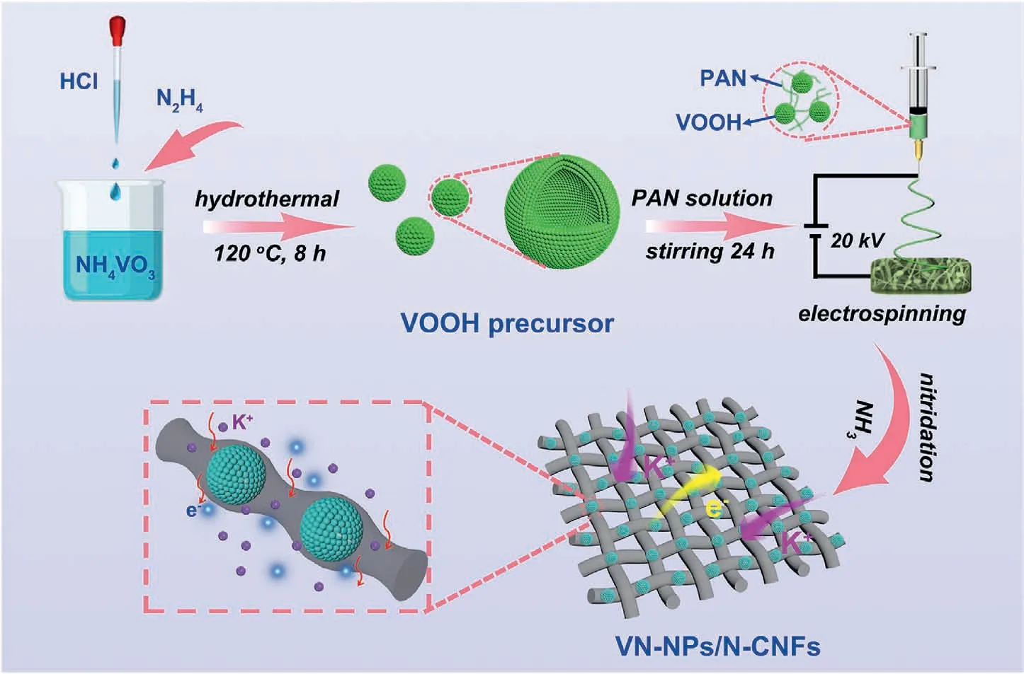
Fig.1.Diagram illustration of the route to fabricate VN-NPs/N-CNFs.
Here we report a design for the production of a hybrid of VN nanoparticle-assembled hollow microspheres encapsulated in N-doped three-dimensional (3D) interconnected carbon nanofibers (VN-NPs/NCNFs) through an electrospinning method.Electrospinning is a facile,efficient,low cost and high yield method for synthesizing nanomaterials,which is beneficial to the building of a carbon framework,and avoids aggregation of the nanoparticles.Particle size diminution reduces the strain and shortens the K+diffusion during the cycling process.The hollow structure offers a cavity to regulate the volumetric variation.The combination of the above mentioned structures for VN-based materials to improve the K storage performance has rarely been reported,but is feasible for PIBs.The VN-NPs/N-CNFs hybrid has the following merits:(i)the VN NPs ensure the full utilization of active materials and shorten the K+diffusion distance;(ii) the N-CNFs connect the VN NP-assembled hollow microspheres in series,prevent their self-agglomeration and promote structural stability;(iii) the hollow architecture assembled by the VN NPs facilitates electrolyte penetration,regulates volume variation and increases the contact areas of the VN NPs with the electrolyte;and(iv) the high N-doping supplies plentiful active sites for K+adsorption and boosts pseudocapacitive effects.The VN-NPs/N-CNFs hybrid electrode exhibits superb rate properties and prolonged life.The practical application of VN-NPs/N-CNFs-600 is verified in the full cell of VN-NPs/N-CNFs-600//potassium Prussian blue nanoparticles (VN-NPs/N-CNFs-600//KPBNPs).
2.Results and discussion
2.1.Architectural characterization
The fabrication of the VN-NPs/N-CNFs composites is displayed in Fig.1.The VOOH precursor was first synthesized by a solvothermal method.Its X-ray diffraction(XRD)pattern is given in Fig.S1,showing its amorphous characteristics.We can see from the field-emission scanning electron microscopy(FESEM)image that the VOOH precursor presents as hollow microspheres(see Fig.S2).It was suggested that the VOOH precursor was generated on the basis of a Kirkendall-effect-induced hollowing behavior [46].The intermediate products were collected at different hydrothermal reaction stages(ranging from 0 min to 600 min),and their morphologies were characterized by transmission electron microscopy (TEM).At the beginning of the hydrothermal reaction,the V(OH)2NH2precursor presented a solid-spherical shape (see Figs.S3a and b).After heating for 90 min,outer shells started to appear (see Fig.S3c).As the reaction proceeded,the inner core shrank,forming a core/shell structure (see Fig.S3d).The inner cores were completely consumed after 210 min (see Fig.S3e) and finally transformed into hollow structures(see Fig.S3f).The relevant reactions are illustrated as follows:
The VOOH/PAN nanofibers were obtained by electrospinning (see Fig.S4).Finally,the VOOH/PAN nanofibers were annealed at 600°C under Ar/NH3flow,forming VN-NPs/N-CNFs (named as VN-NPs/NCNFs-600).In order to optimize the VN content in the VN-NPs/NCNFs,three other hybrids were also prepared by adjusting the weight of the VOOH precursor(0,0.3 and 0.6 g)in a process similar to that used for the VN-NPs/N-CNFs-600 (the weight of the VOOH precursor is 0.45 g).These three hybrids were defined as N-CNFs,VN-NPs/N-CNFs-600(0.3) and VN-NPs/N-CNFs-600 (0.6),respectively.Other annealing temperatures of 500°C and 700°C(defined as VN-NPs/N-CNFs-500 and VN-NPs/N-CNFs-700,respectively) were used to optimize the ammonia reduction temperature.For a comparison,VN nanoparticles without electrospinning (denoted as VN-NPs below) were also synthesized.To demonstrate the advantage of the hollow nanostructure,the VN solid spheres confined in carbon nanofibers(denoted as s-VN/N-CNFs)hybrid was also prepared.
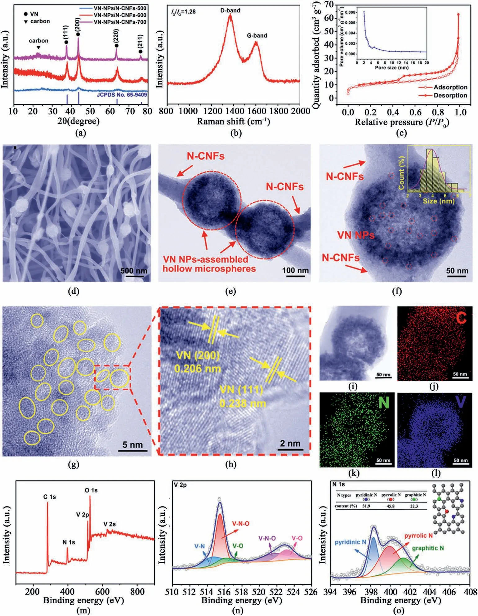
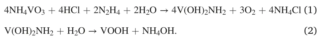
Fig.2.(a)XRD patterns of VN-NPs/N-CNFs-500,VN-NPs/N-CNFs-600 and VN-NPs/NCNFs-700.(b) Raman spectrum,(c) N2 adsorption/desorption isotherms of VN-NPs/N-CNFs-600.The inset of (c) is the pore size distribution of VN-NPs/N-CNFs-600.(d)FESEM,(e) and (f) TEM images of VN-NPs/N-CNFs-600.The inset of (f) shows the particle size distribution.(g,h) HRTEM images,(i–l) scanning TEM and corresponding elemental mappings of VN-NPs/N-CNFs-600.(m)XPS survey spectrum,(n)V 2p and(o)N 1s high-resolution XPS spectra of VN-NPs/NCNFs-600.
Fig.2a compares the XRD patterns of VN-NPs/N-CNFs-500,VN-NPs/N-CNFs-600 and VN-NPs/N-CNFs-700,where the broad band between 20°and 30°corresponds to the(002)plane of amorphous carbon.Other peaks belong to the planes of the VN phase(JCPDS No.65–9409),which look very similar to those of VN-NPs(see Fig.S5).Based on the Scherrer equation,the average size of the VN NPs in the VN-NPs/N-CNFs-600 hybrid is about 5.1 nm.The VN-NPs/N-CNFs-500 hybrid shows inferior crystallinity due to its lower annealing temperature.In the case of VNNPs/N-CNFs-700,the sharper diffraction peaks indicate the increased crystallinity and grain size of the VN particles (~23.2 nm based on the Scherrer formula).The Raman spectrum of the VN-NPs/N-CNFs-600 composite is displayed in Fig.2b.TheID/IGratio is around 1.28,revealing a low-crystallinity amorphous carbon with abundant disorders and defects in the N-CNFs [47–51].VN-NPs/N-CNFs-600 possesses the largest surface area of 33.4 m2g-1,compared with VN-NPs (19.8 m2g-1),N-CNFs (5.7 m2g-1),VN-NPs/N-CNFs-500 (12.6 m2g-1) and VN-NPs/N-CNFs-700(28.3 m2g-1)(see Fig.2c,Fig.S6 and Fig.S7).As measured by the Barrett-Joyer-Halenda method,the pore sizes of VN-NPs/N-CNFs-600 are approximately 2–5 nm.The abundant porosity is conducive for the infiltration of the electrolyte and K+transport,which can boost the pseudocapacitive behavior,promoting the electrochemical performance [50,52].The content of VN in VN-NPs/N-CNFs-600 was calculated by thermogravimetric analysis (TGA),as shown in Fig.S8.According to the equation in Fig.S8,the final weight percentage of VN in the VN-NPs/N-CNFs-600 composite is 50.7%.The corresponding VN contents in the VN-NPs/N-CNFs-600 (0.3) and VN-NPs/N-CNFs-600(0.6) hybrids are approximately 36.8 wt% and 61.1 wt%,respectively(see Fig.S9).From the FESEM image of VN-NPs/N-CNFs-600 (see Fig.S10 and Fig.2d),we can see that plenty of VN NP-assembled microspheres are encapsulated within the carbon fibers and are well linked along the nanofibers.In contrast,VN-NPs without electrospinning are aggregated into stacks(see Fig.S11).This implies that N-CNFs can inhibit the aggregation of VN NPs and inherit the original shape of the precursor.Fig.S12 shows the FESEM images of N-CNFs,VN-NPs/N-CNFs-600(0.3)and VN-NPs/N-CNFs-600(0.6).When the VN content is zero,i.e.N-CNFs,only carbon fibers can be observed (see Fig.S12a).For the VN-NPs/N-CNFs-600 (0.3) hybrid,a few VN NP-assembled hollow microspheres are distributed along the N-CNFs,while N-CNFs are major(see Fig.S12b).As for the VN-NPs/N-CNFs-600 (0.6) hybrid,some VN NP-assembled hollow microspheres are aggregated together (see Fig.S12c).Thus,the VN-NPs/N-CNFs hybrids mentioned below refer to the VN content of 50.7%.The FESEM images of VN-NPs/N-CNFs-500 and VN-NPs/N-CNFs-700 are given in Fig.S13.VN-NPs/N-CNFs-500 exhibits a morphology similar to that of VN-NPs/N-CNFs-600,whereas in VN-NPs/N-CNFs-700,with increasing temperature,some carbon nanofibers were partly destroyed.Fig.2e displays a TEM image of VN-NPs/N-CNFs-600,where VN NP-assembled hollow microspheres(marked by the red dotted circles)are wrapped in the N-CNFs.As shown in a TEM image of VN-NPs/N-CNFs-600 at higher magnification (see Fig.2f),every hollow microsphere unit is built up by abundant highly-dispersed VN NPs,and the mean size of the VN NPs is only 4.2 nm in accordance with its XRD result.TEM images of VN-NPs/N-CNFs-500 and VN-NPs/N-CNFs-700 (see Fig.S14) further verify the XRD results.For VN-NPs/N-CNFs-500,the average size of the VN NPs is around 3.8 nm,while for VN-NPs/N-CNFs-700,the VN NPs grow to~16 nm.The high-resolution TEM (HRTEM) images of VN-NPs/N-CNFs-600 (see Fig.2g and h) further verify the average diameter of the VN NPs is~4 nm.Moreover,the interplanar spacings(0.206 and 0.238 nm)come from the(200)and(111)planes,respectively,of the VN phase.Scanning TEM and corresponding elemental mappings of VN-NPs/N-CNFs-600 (see Fig.2i-l)imply the homogeneous distribution of C,N and V throughout the hybrid.

Fig.3.(a) CV,(b) charge/discharge profiles of the VN-NPs/N-CNFs-600 electrode.(c)Cycling stability of VN-NPs/N-CNFs-600 and VN-NPs at 0.1 A g-1.(d) Rate property of VN-NPs/N-CNFs-600 and VN-NPs.(e) Rate property of VN-NPs/N-CNFs annealed at different temperatures of 500,600 and 700°C.(f) Long cyclability of VN-NPs/N-CNFs-600 and VN-NPs.(g) TEM image of VNNPs/N-CNFs-600 after 2000 cycles.(h) Capacities of the VN-NPs/N-CNFs-600 electrode,compared with other reported works,such as VN-QDs/CM [43],HHS-VN@C [44],VN/CNFs [45],m-NbN/NC [64] and Fe2N@N-CFBs [65].(i) Cycling performance of the VN-NPs/N-CNFs-600 electrode,compared with other reported works,such as VN-QDs/CM [43],HHS-VN@C [44],VN/CNFs [45],m-NbN/NC [64] and Fe2N@N-CFBs [65].
The chemical and electronic states of VN-NPs/N-CNFs-600 are explored by X-ray photoelectron spectroscopy (XPS).Fig.2m shows the full XPS spectrum of VN-NPs/N-CNFs-600,which displays the signals of C,N,V and O.The C 1s XPS spectra(see Fig.S15),contains C–C(284.5 eV),C–O/C–N(286.2 eV)and C––O(288.3 eV)bonds.Fig.2n describes the V 2p XPS spectra,containing the V–N(514.5 eV),V–N–O(515.5 and 522.7 eV) and V–O (516.3 and 523.1 eV) bonds.The N content on the VN-NPs/N-CNFs-600 surface is estimated to be 13.1 at%.The ultra-high N doping can induce plenty of vacancies and active sites for electron transport and K+adsorption [53–55].For the N 1s XPS spectra (see Fig.2o),three types of N at 398.3,400.1 and 401.3 eV refer to pyridinic-,pyrrolic-and graphitic-N,respectively.Their atomic percentages are given in the inset of Fig.2o.The relative high pyridinic/pyrrolic-N in VN-NPs/N-CNFs-600 is conducive for the adsorption of K+.
2.2.Potassium storage performance
The K storage performance and electrochemical reaction mechanism of VN-NPs/N-CNFs were evaluated via as-assembled 2025 coin-type halfcell.Fig.3a depicts cyclic voltammetry (CV)curves of VN-NPs/N-CNFs-600,which are distinct from those of N-CNFs (see Fig.S16).The wide peak (0.55 V) which just appeared during the initial scan is assigned to the reaction of VN+3 K++3e-→V+K3N,and the generation of solid electrolyte interface(SEI)layers.Then it moves to 0.61 V in subsequent cycles and its current intensity decreases [41].The couple of sharp cathodic (0.01 V) and broad anodic (0.54 V) peaks refer to the insertion/extraction of K+into/from N-CNFs,respectively [56].The wide peak at 1.30 V is assignable to the transformation from V to VN [41].Note that weak reduction peaks may result from the existence of capacitive behavior [57–63].Similar phenomena can be found in other VN-based anode materials for PIBs[43–45].The high overlap of the CV cycles from the second cycle indicates the reversibility of the K+storage in the VN-NPs/N-CNFs-600 electrode.The total mechanism reaction of the VN-NPs/N-CNFs-600 electrode is expressed as follows[43].
The discharge reaction:

The charge reaction:


Fig.4.(a) CV profiles of the VN-NPs/NCNFs-600 electrode at various scan speeds.(b) Log(i)-log(v) plots.(c) Proportions of diffusion-controlled and capacitive (shaded area) portions for the VN-NPs/N-CNFs-600 electrode at 0.8 mV s-1.(d) Proportions of capacitive portion for the VN-NPs/N-CNFs-600 electrode at different scan speeds. Exsitu HRTEM images of VN-NPs/N-CNFs-600 after (e) fully discharged and (f) fully charged.(g) Scanning TEM image,and EDS mappings for (h) C,(i) N,(j) V and (k) K in the VN-NPs/N-CNFs-600 electrode after fully discharged.(l) Scanning TEM image,and EDS mappings for(m)C,(n)N,(o)V and(p)K in the VN-NPs/N-CNFs-600 electrode after fully charged.(q) Scheme representation of the advantages of VN-NPs/N-CNFs-600 during cycling.
Fig.3b and Fig.S18 display the charge/discharge profiles of the VNNPs/N-CNFs-600 and VN-NPs electrodes,respectively.In this work,all the capacities are evaluated by the whole weight of the VN-NPs/N-CNFs.The VN-NPs/N-CNFs-600 electrode delivers initial discharge/charge capacities of 1461.5/599.6 mAh g-1,rendering a Coulombic efficiency(CE) of 41.0%.It primarily results from the establishment of SEI films over the surface of the electrode.The capacity of the VN-NPs/N-CNFs-600 is approximately an algebraic average of VN and N-CNFs based on their capacities and contents(the weight percentages of VN and N-CNFs are 50.7% and 49.3%,respectively).The capacities of the N-CNFs and VN-NPs/N-CNFs-600 electrodes for the second cycles are 311.1 and 834.2 mAh g-1,respectively (see Fig.S17 and Fig.3b).The corresponding capacity contributions of N-CNFs and VN are 18.4% (=311.1×49.3%/834.2)and 81.6%,respectively.The reversible capacity of VNNPs/N-CNFs-600 at the second cycle is the highest among the ever reported metal nitrides-based anodes[43–45,64,65].Fig.3c demonstrates the VN-NPs/N-CNFs-600 electrode has a capacity of 371.9 mAh g-1after 100 cycles,surpassing the VN-NPs electrode (only 114.1 mAh g-1) and other reported metal nitride-based anodes (see Fig.3i) [43–45,64,65].Compared with the VN/CNFs hybrid reported by Xu et al.[45],the main advantage of VN-NPs/N-CNFs in our work is the hollow structure,which can offer a cavity to adjust volume variation during cycling and benefit electrolyte penetration.Moreover,the N-CNFs offer a continuous and conductive framework,thus strengthening the structural stability of the VN-NPs/N-CNFs-600 hybrid.Thus,the VN-NPs/N-CNFs hybrid combines the advantages of VN NP-assembled hollow microspheres and the interconnected N-CNFs framework.To further demonstrate the advantage of the hollow nanostructure,the s-VN/N-CNFs hybrid was also prepared.The XRD pattern,TEM image and cycling stability of the s-VN/N-CNFs hybrid are depicted in Fig.S19.The s-VN/N-CNFs electrode holds a capacity of 171.6 mAh g-1,inferior to that of the VN-NPs/N-CNFs-600 (371.9 mAh g-1),demonstrating the great advantages of the hollow structure.It can be observed that the CE of the VN-NPs/N-CNFs-600 electrode gradually increased to 100% until the 20th cycle,due to the foundation and stabilization of SEI films.Similar phenomena have been discovered in other PIB anodes,such as carbon-based materials[66,67],MoP/N,P-doped carbon nanofibers[68],VSe2nanosheets[12]etc.The rate properties of the VN-NPs/N-CNFs-600 and VN-NPs electrodes are presented in Fig.3d.The corresponding charge/discharge profiles of the VN-NPs/N-CNFs-600 electrode are displayed in Fig.S20.The VN-NPs/N-CNFs-600 electrode acquires reversible capacities of 542.8,317.6,269.7,235.4,201.6,161.9 and 140.2 mAh g-1at 0.1,0.2,0.5,1,2,5 and 10 A g-1,respectively.All these results are superior to that of the VN-NPs electrode.The effect of VN contents on rate properties is shown in Fig.S21.From the figure,the VN-NPs/N-CNFs-600 electrode displays higher average capacities at 0.5–10 A g-1,than the N-CNFs(161.3,134.8,110.4,85.9 and 75.7 mAh g-1),VN-NPs/N-CNFs-600 (0.3) (214.3,165.4,128.7,71.6 and 57.3 mAh g-1) and VN-NPs/N-CNFs-600 (0.6) (265.3,216.4,171.5,118.5 and 90.1 mAh g-1) electrodes.Note that the capacities of VN-NPs/N-CNFs-600(0.6)are slightly higher at 0.1 and 0.2 A g-1.This may originate from the high theoretical capacity and content of VN.Such a superior electrochemical property of VN-NPs/N-CNFs-600 lies in the uniform distribution of VN NP-assembled hollow microspheres along the N-CNFs(see Fig.2d and Fig.S12).This confirms that the VN content of 50.7 wt% is the optimum among these samples.To explore the appropriate annealing temperature,the rate properties of the samples annealed at 500,600 and 700°C were also evaluated (see Fig.3e).The VN-NPs/N-CNFs-600 electrode shows the optimum rate property.This is attributed to the following aspects.Firstly,from Fig.2a,VN-NPs/N-CNFs-600 possesses excellent crystallization.VN-NPs/N-CNFs-500 shows inferior crystallinity due to its lower annealing temperature.Secondly,VN-NPs/N-CNFs-600 displays a small size of 4.2 nm(see Fig.2f),which guarantees the full utilization of active materials,while the VN NPs in VN-NPs/N-CNFs-700 grow to~16 nm(see Fig.S14).Finally,VN-NPs/N-CNFs-600 has the largest specific area among these three samples (see Fig.2c and Fig.S7),which provides efficient electrolyte diffusion paths.Therefore,VN-NPs/N-CNFs-600 displays the best potassium storage properties among these three hybrids.It is noteworthy that VN-NPs/N-CNFs-600 shows the most outstanding rate performance among the reported metal nitride-based anodes (see Fig.3h).This benefits from the synergistic effect of (i) VN NPs for guaranteeing the full utilization of active materials;(ii) interconnected carbon nanofibers for promoting the structural stability and accelerating electron/ion transport;(iii) the hollow architecture assembled by the VN NPs for electrolyte penetration,mitigating the volume variation and increasing the contact areas between the electrolyte and VN NPs;and (iv)high N-doping for providing numerous active sites for K+adsorption.The superb rate properties of VN-NPs/N-CNFs-600 may also result from its lower internal resistance,which is attested to by electrochemical impedance spectroscopy (EIS) analysis.The VN-NPs/N-CNFs-600 electrode shows the smallest charge transfer resistanceRct(583 Ω),compared with the VN-NPs/N-CNFs-500 (927 Ω),VN-NPs/N-CNFs-700 (881 Ω) and VN-NPs (1250 Ω) electrodes (see Fig.22).
Fig.5.(a)Schematic diagram,(b)charge/discharge profiles,(c)cycling stability of the VN-NPs/N-CNFs-600//KPBNPs full cell.(d)Optical photograph of a string of colorful LEDs lightened by the full cell.
Electrolytes play an important role in the development of highperformance PIBs,including the selection of potassium salt,solvent and electrolyte concentration,as well as the introduction of electrolyte additives [69–72].The VN-NPs/N-CNFs-600 electrode in two other electrolytes [4 M KFSI in ethylene carbonate/diethyl carbonate (4 M KFSI-EC/DEC)and 1 M KPF6in dimethoxyethane(1 M KPF6-DME)]were also tested to measure the effect of the electrolyte on the rate property of the VN-NPs/N-CNFs-600 electrode (see Fig.S23).From the figure,compared with the VN-NPs/N-CNFs-600 electrode in 0.8 M KPF6-EC/-DEC,the VN-NPs/N-CNFs-600 electrode in 4 M KFSI-EC/DEC delivers lower capacities.The VN-NPs/N-CNFs-600 electrode in 1 M KPF6-DME shows higher capacities under 0.1–1 A g-1,while it is obviously declined at 5 and 10 A g-1.Possible reasons are as follows:(i) the KFSI-based electrolyte is more suitable in dimethyl carbonate (DMC) solvent;and(ii) stable SEI films may form in the DME electrolyte system at the beginning of the cycling process.However,ether-based electrolytes generally experience relatively poor oxidation resistance,resulting in capacity fading during the cycling process.Therefore,0.8 M KPF6-EC/-DEC was selected as the electrolyte in our case.The optimization of the electrolyte and the corresponding mechanism need to be studied further in the future.
Fig.3f compares the long-term cycling of the VN-NPs/N-CNFs-600 and VN-NPs electrodes at 0.5 A g-1.To form steady SEI films,the electrodes were all cycled first for five cycles at 0.1 A g-1.The capacities of the VN-NPs/N-CNFs-600 electrode for the 500th and 2000th cycles were 231.6 and 226.9 mAh g-1,respectively,revealing superior stability to those of VN-QDs/CM (215 mAh g-1,500 cycles) [43] and m-NbN/NC(100 mAh g-1,2000 cycles) [64].As displayed in the FESEM (see Fig.S24)and TEM(see Fig.3g)images,the VN-NPs/N-CNFs-600 hybrid keeps its original structure after 2000 cycles,which attests to its superb structural stability.XPS analysis of the VN-NPs/N-CNFs-600 electrode was also performed after the cycling tests to assess its durability (see Fig.S25).From the survey spectrum (see Fig.S25a),we can see the signals of C,N,V,O and K.The K signal results from the residual K in the SEI films[73,74].As shown in Fig.S25b,the peak at 284.8 eV refers to the C–C bond in the VN-NPs/N-CNFs-600 hybrid.Three other peaks are ascribable to C–O,C––O and,respectively[75,76].These peaks are reflected in the O 1s spectra (see Fig.S25c) [77,78].All the chemical compositions result from the SEI films caused by the decomposition of the electrolyte [79,80].In addition,the V 2p XPS spectra show the V–N–O(515.9 and 522.3 eV),V–O(516.9,523.1 and 525.7 eV)and V–N(514.7 eV) bonds,which mostly preserve the original chemical composition in the hybrid before cycling.This shows the high stability of VN-NPs/N-CNFs-600.Note that the content of vanadium oxides increases due to the decomposition of the electrolyte since the O element mainly originated from ester molecules [75].While at 1 A g-1,VN-NPs/N-CNFs-600 still holds capacities of 187.2 mAh g-1(300 cycles),175.5 mAh g-1(1000 cycles) and 170.5 mAh g-1(2000 cycles) (see Fig.S26),which is higher than the HHS-VN@C electrode(181 mAh g-1,300 cycles)[44]and the VN/CNFs electrode(152 mAh g-1,1000 cycles)[45](see Fig.3i).
2.3.Potassium storage mechanism
To further assess the electrochemical behaviors of VN-NPs/N-CNFs-600,CV profiles at various scanning speeds in the range of 0.2–1.2 mV s-1(see Fig.4a)were used to analyze its reaction dynamics.The peak current (i) and scanning speeds (v) comply with the following equation[81–83]:

Abvalue near 0.5 implies diffusion control,while approaching to 1,it reflects capacitive behavior.Thebvalues calculated for the VN-NPs/NCNFs-600 electrode (see Fig.4b) are 0.82 for the anodic peak and 0.78 for the cathodic peak,which implies that the electrochemical kinetics is mainly capacitive-dominated.The ratio of the contributions of the capacitive(k1v)and the diffusion behavior(k2v1/2)is determined by the following formula[81–83]:

wherek1andk2are constant coefficients.The calculated capacitivecontrolled contribution of the VN-NPs-N-CNFs-600 electrode is 66.2%at 0.8 mV s-1.Then it enhances to 72.7% when the scanning speed increases to 1.2 mV s-1(see Fig.4c and d).Such a majority contribution of the pseudocapacitive process is conducive to the enhancement of the electrochemical performance of the VN-NPs/N-CNFs-600 electrode.
To deeply assess the electrochemical reaction of the VN-NPs/N-CNFs-600 electrode,ex-situHRTEM were adopted to record the evolution of the microstructure after the 1st charge/discharge.From Fig.4e and f,when discharged to 0.01 V,we can see the appearance of V and K3N.After being fully charged,only VN is discerned.Based on these observations,the reaction mechanism mentioned above is further validated.Additionally,on the energy dispersive spectrum (EDS) mappings of the VNNPs/N-CNFs-600 electrode after discharge,elements C,N,V and K are distributed evenly on the whole electrode(see Fig.4g–k).The stronger K intensity originates from the formation of SEI films and K3N.After being charged to 3 V (see Fig.4l–p),the relatively weak but homogeneous K EDS mapping reveals the remaining K in the SEI films and the even generation of SEI films on the VN-NPs/N-CNFs-600 electrode surface[84–86].
All the data discussed above reveal that the electrochemical performance of VN-NPs/N-CNFs-600 is attributable to the interconnected conductive network structure consisting of VN-NP assembled hollow microspheres and N-CNFs,namely,VN NPs for guaranteeing the full utilization of active materials;interconnected carbon nanofibers for ensuring efficient electrolyte diffusion and accelerating rapid electron/ion transport;the hollow architecture assembled by the VN NPs for electrolyte penetration,buffering the volume variation and increasing the contact areas between the electrolyte and VN NPs;and high N-doping for K+adsorption(see Fig.4q).
2.4.Electrochemical performance of the K+ full cell
Due to the excellent viability of VN-NPs/N-CNFs-600 in the half cell setup,we tested potassium-ion full cells(see Fig.5a).The XRD pattern and cycling stability of KPBNPs(see Fig.S27 and Fig.S28) are in accordance with the ever reported work[19].The low CEs of the KPBNPs cathode are presumably related to the crystal water in the KPBNPs lattice.The crystal water is difficult to thoroughly remove from the interstice.During the charge process,the crystal water would decompose and result in partial capacity loss,thus causing low CEs.During the cycling,the crystal water content decreases and thus the CEs gradually increase [87–89].The capacity fading of the KPBNPs cathode may be due to the generation of SEI films,structural degradation resulting from crystal water,and irreversible reactions between Fe4[Fe(CN)6]3and potassium [90–92].The VN-NPs/N-CNFs-600//KPBNPs full cell possesses a capacity of 148.6 mAh g-1after 100 cycles (see Fig.5b and c).Note that the capacities are evaluated according to the mass of the VN-NPs/N-CNFs-600 anode.The CEs for the VN-NPs/N-CNFs-600//KPBNPs full cell are below 100%,which is caused by KPBNPs with relatively low CEs and an un-optimized cathode and anode weight ratio,resulting in partial capacity loss.Further efforts are needed to focus on the cathode materials and the optimization of the cathode and anode weight ratio.After being fully charged,the VN-NPs/N-CNFs-600//KPBNPs full cell can light a string of colorful light-emitting diodes(LEDs)(see Fig.5d).
3.Conclusion
In summary,a VN-NPs/N-CNFs hybrid was designed and fabricated by a facile electrospinning method.The coexistence of VN NPs and high N-doping carbon nanofibers endows the composite with the advantages of an interconnected conductive network structure,abundant utilization of active sites and robust structural stability,which ensures electrolyte diffusion,shortens the ion transport pathways and facilitates rapid ionic/electronic transport.Therefore,the VN-NPs/N-CNFs-600 electrode displays prominent rate performance and prolonged cycle life.This work not only develops a novel anode material for PIBs,but also opens up the possibility to design appropriate materials for innovative energy storage systems.
Declaration of competing interest
There are no conflicts to declare.
Acknowledgments
We wish to thank the National Natural Science Foundation of China(No.51631004),the Project of Talent Development in Jilin Province,the Natural Science Foundation of Jilin Province(No.20200201073JC),the Program for JLU Science and Technology Innovative Research Team(No.2017TD-09),the Graduate Innovation Fund of Jilin University (No.101832020CX146),and the Fundamental Research Funds for the Central Universities for their financial support.
Appendix A.Supplementary data
Supplementary data to this article can be found online at https://doi.org/10.1016/j.nanoms.2021.06.007.

- Namo Materials Science的其它文章
- Preface of “Trends in Nanomaterials and Nanocomposites:Fundamentals,Modelling and Applications”
--Festschrift in honor of Prof Yiu-Wing Mai's 75th birthday - A comparative study of 85 hyperelastic constitutive models for both unfilled rubber and highly filled rubber nanocomposite material
- On mechanical properties of nanocomposite hydrogels:Searching for superior properties
- Ultra-transparent nanostructured coatings via flow-induced one-step coassembly
- Molecular dynamics study on mechanical behaviors of Ti/Ni nanolaminate with a pre-existing void
- Core-shell structured silk Fibroin/PVDF piezoelectric nanofibers for energy harvesting and self-powered sensing