
Core-shell structured silk Fibroin/PVDF piezoelectric nanofibers for energy harvesting and self-powered sensing
2022-07-26 09:21SiqiWngKunmingShiBinChiShichongQioZhuoliHungPingkiJingXingyiHung
Namo Materials Science 2022年2期
Siqi Wng ,Kunming Shi ,Bin Chi ,Shichong Qio ,Zhuoli Hung ,Pingki Jing ,Xingyi Hung,*
a Department of Polymer Science and Engineering,Shanghai Key Laboratory of Electrical Insulation and Thermal Aging,Shanghai Jiao Tong University,Shanghai,200240,China
b Department of Implantology,Shanghai Ninth Peoples' Hospital,College of Stomatology,Shanghai Jiao Tong University School of Medicine,National Clinical Research Center for Oral Diseases,Shanghai Key Laboratory of Stomatology & Shanghai Research Institute of Stomatology,Shanghai,China
Keywords:PVDF Silk fibroin Piezoelectric Electrospinning Nanofiber
ABSTRACT The development of wearable and portable electronics calls for flexible piezoelectric materials to fabricate selfpowered devices.However,a big challenge in piezoelectric material design is to boost the output performance while ensuring its flexibility and biocompatibility.Here,all-organic and core-shell structured silk fibroin (SF)/poly(vinylidene difluoride)(PVDF)piezoelectric nanofibers(NFs)with excellent flexibility are fabricated using a simple electrospinning strategy.The strong intermolecular interaction between SF and PVDF promotes the β-phase nucleation in the core-shell structure,which significantly enhances the output performance.An output of 16.5 V was achieved in SF/PVDF NFs,which is more than 6-fold enhancement compared with that of pure PVDF NFs.In addition,the piezoelectric device can sensitively detect the mechanical stimulation from joint bending,demonstrating its great potential in self-powered sensor.Otherwise,the piezoelectric device can be also applied to control the movement of a smart car,successfully,achieving its application in the human-machine interaction.
1.Introduction
The age of the Internet of Things (IoT) has witnessed the rapid development of wearable electronics,which are highly demanded in various potential applications,such as smart textiles [1,2],motion tracking [3],and health monitoring [4,5].Recently,tremendous efforts have been made to design mechanically sensitive,flexible,and robust wearable electronic devices[6,7].However,in the practical application,energy supply is still a crucial issue for its development [8].For now,wearable sensing devices mainly rely on an external power supply,e.g.,batteries,which cause further issues like additional power consumption as well as limitations on dimension and flexibility[9].
Piezoelectric material that can spontaneously harvest mechanical energy from human motions have been demonstrated as a promising candidate in wearable and self-powered sensing [10–12].Piezoelectric ceramics or semiconductors,such as lead zirconate titanate[13]and zinc oxide[14],are mechanical brittleness and rigidness,which restricts their applications in wearable devices despite the high piezoelectric performance.As another cluster of piezoelectric material,piezoelectric polymers have drawn numerous interests from investigators due to their excellent mechanical flexibility and machinability [15,16].Typically,polyvinylidene fluoride (PVDF) has different crystalline phases that related to different chain conformations,in which electroactive β phase contributes most to the piezoelectric property of PVDF [17,18].In addition,PVDF has been considered as a kind of highly attractive polymer for biomedical device due to its biocompatibility.
Considering its low piezoelectric performance,different strategies varying from processing techniques to material components have been developed to enhance the piezoelectric output of PVDF-based materials to meet their practical requirements[19–24].An efficient approach is to introduce specific fillers into polymer matrix,such as barium titanate(BTO) nanoparticles [25,26],lead zirconate titanate(PZT) [27],carbon nanotubes(CNTs)[28],and graphene[29].However,the aggregation of nanofillers is one of the biggest problems,which restricts the output performance [30].An additional concern is that some doped inorganic fillers aforementioned are toxic and biological incompatibility,which restrict their practical application in the fields of biomedical and wearable electronics[31].As a type of biomaterial,silk fibroin(SF)extracted from silkworm cocoons,is widely used for biomedical engineering[32–34].Thanks to the unique hierarchical and chemical structure of natural silk fibers,silk-based materials that processed by various fabrication strategies have excellent mechanical property and electroactive properties,which have been extensively investigated in wearable electronics[35–40].
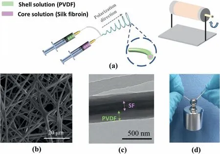
Fig.1.(a) Schematic illustration of the coaxial electrospinning process.(b) SEM image and (c) TEM image of SF/PVDF nanofibers.(d) The high flexibility and mechanical strength of SF/PVDF piezoelectric nanofiber mats (yarn diameter:~1 mm;yarn length:~10 cm;mass of weight:50 g).
Herein,flexible core-shell SF/PVDF composite nanofibers (NFs) are fabricated through coaxial electrospinning technique to realize the piezoelectric performance improvement of PVDF without inorganic fillers.It is found that the interaction between PVDF and SF molecules contributes to the increasement of piezoelectric β phase,resulting in performance enhancement of the piezoelectric devices.The piezoelectric device based on SF/PVDF composite NFs with 14 wt% SF can yield an output voltage of 16.5 V.Under periodic bending stimulation,the piezoelectric energy can be stored in commercial capacitors and the piezoelectric output shows no degradation in a long-term durability test,which demonstrates its great potential in scavenging mechanical energy and serving as self-powered electronics.Furthermore,SF/PVDF composite nanofibers-based flexible device is successfully applied as a selfpowered sensor to monitor the human joint motions,and control a smart car movement through a human-machine interaction.Hence,the core-shell structured flexible SF/PVDF composite NFs could be a promising candidate for high-performance and self-powered electronics in practical usage scenarios.
2.Experimental section
2.1.Fabrication of the silk fibroin solution
Bombyx moricocoons (Fig.S1a) cut into small pieces were boiled in 0.02 M sodium carbonate (Na2CO3) aqueous solution for 40 min to remove the sericin.The obtained silk fibers were rinsed three times by deionized water and dried in a fume hood overnight.Then,the silk fibers were dissolved in 9.3 M lithium bromide(LiBr)solution under 60°C for 4 hours to get a transparent solution.LiBr was removed by dialysis(3500 D,Viskase) for 48 h against deionized water.The resulting silk fibroin solution was centrifuged to remove impurities.The concentration of the silk fibroin solution is about 2.5 wt%determined by measuring residual weight after drying.Silk fibroin solution with a higher concentration can be obtained by condensing against polyethylene glycol (PEG,Mn=100,000).To avoid the gelation effect,the silk fibroin solution was stored at 4°C.
2.2.Fabrication of piezoelectric core-shell fibers
PVDF(Solef,6010)powders were dissolved in a mixed solvent of N,N-Dimethylformamide (DMF) and acetone (6:4 by weight/weight) by stirring at 60°C for 3 h to obtain a transparent solution.SF/PVDF piezoelectric NFs were obtained by a coaxial electrospinning.The shell PVDF solution and the core silk fibroin solution were put into two separate syringes connected to the spinneret and fed at different rates.The size of the inner and outer needles are 17 gauge and 22 gauge,respectively.The feed rate ratio of the inner and outer layers was adjusted to obtain the composite NFs with SF content of 7 wt%,14 wt%,and 20 wt%.The obtained samples are labeled as pure PVDF,SF/PVDF-7,SF/PVDF-14,and SF/PVDF-20.The electrospinning voltage was set at 15 kV.The nanofibers were collected by a collector with a rotation speed of 1200 rpm,and the distance from the needle tip to the collector was set at 15 cm.The obtained electrospinning mats were subsequently dried at 50°C and annealed at 160°C.
2.3.Fabrication of piezoelectric device
Aluminum foils(25 mm×25 mm)were attached on both sides of the tailored nanofiber mat (thickness:~20 μm;size:30 mm × 30 mm),serving as top and bottom electrodes of piezoelectric devices.Then,polyethylene terephthalate(PET)films were used to package the device to avoid the external mechanical damage.Finally,the fabricated device was subjected to a proper stress to make the device compact.

Fig.2.(a)DSC spectra of PVDF NFs and SF/PVDF NFs.(b)The variation of the calculated crystallinity of PVDF in the composite NFs.(c)FT-IR spectra of PVDF NFs and SF/PVDF NFs.(d) The variation of β phase fraction in the composite NFs.(e) Schematic diagram of the interaction between SF and PVDF chain.
2.4.Characterization and measurements
Surface morphologies of core-shell NFs were characterized with SEM(Nova NanoSEM 450,FEI,USA).A thin layer of gold was sputtered onto the SEM sample surface.The structure of coaxial NFs was characterized using a transmission electron microscope(JEM-2010,JEOL,Japan)with an accelerating voltage of 200 kV.Differential scanning calorimetry(NETZSCH 200F3)was conducted under a nitrogen atmosphere over the range of 20–200°C.The heating and cooling rates were both 10°C/min.Fourier transform infrared (FTIR) spectroscopy of the nanofiber mats were characterized by a PerkinElmer Paragon 1000 spectrometer in the attenuated total reflectance (ATR) mode over the range of 4000–400 cm-1.A customized linear motor was used to drive the piezoelectric devices.The output voltage and current of the piezoelectric devices were measured by an oscilloscope(TDS 2014,Tektronix,10 MΩ internal resistance) and a source meter (Keithley 2450,USA),respectively.
3.Results and discussion
Fig.1a shows the schematic illustration of the coaxial electrospinning process.With the feeding of core solution of silk fibroin and shell solution of PVDF,the core-shell structure of SF/PVDF can be achieved by electric drawing and solvent evaporation.The surface morphology of the composite NFs is illustrated by SEM image in Fig.1b,where no bead or nonvolatilized solvent is observed.Due to the low rotation rate of the collector,the electrospun fibers tends to be randomly oriented,resulting in isotropous physical characteristics in mat plane.To verify the coaxial structure of SF/PVDF NFs,TEM was conducted and the image shows in Fig.1c.One can see that the composite NF exhibits distinct contrast difference in bright shell region and dark core region,which correspond to PVDF layer and SF layer,respectively.In addition,the core layer of SF is completely and uniformly coated by PVDF shell,and well oriented in the fiber axis direction.For comparation,the pristine PVDF do not form the core-shell microstructure during electrospinning (Fig.S2).As expected,the diameter of the core layer becomes larger as the feeding rate of SF increase (Fig.S3).Fig.1d demonstrates the flexibility and mechanical strength of the prepared composite NFs,which were twisted into a yarn and could bear a 50 g weight.
To better understand the role of SF in the core-shell structured composite NFs,we prepared SF/PVDF NFs with different SF contents and compared their difference through differential scanning calorimetry(DSC) and Fourier transform infrared (FTIR) spectroscopy.DSC thermograms in Fig.2a illustrate the higher melting temperature of SF/PVDF NFs compared with pure PVDF NFs.Moreover,the melting peak of SF/PVDF NFs shifts toward higher temperature with increasing SF feeding rate.The crystallinity(Xc)of PVDF can be calculated using the equation as follows[41]:

Fig.3.Schematic diagram of (a) the structure and (b)the flexibility of the piezoelectric device based on SF/PVDF nanofibers.Time dependence of (c) open-circuit voltages and (d) short-circuit current of PVDF and SF/PVDF piezoelectric devices under a frequency of 2 Hz and a strain of 4 mm.(e) Frequency dependence and(f) Strain dependence of output voltages of the SF/PVDF-14 piezoelectric device.

WhereXcis the crystallinity of PVDF,ΔHmis the melting enthalpy of the sample,φ is SF content in this work,(104.6 J/g)is the standard melting enthalpy of PVDF with complete crystallization.The calculated crystallinity of PVDF is shown in Fig.2b.One can see that the crystallinity of PVDF increases along with the SF content and achieves the highest value of 68%at a SF content of 20 wt%.The result indicates that the SF in the core layer efficiently enhanced the thermostability of the composite fibers and induced the crystallization of PVDF in the outer layer.Specifically,the SF in core-shell nanofiber plays a role of heterogeneous nucleating agent in the crystallization process of PVDF,providing the substrates for the formation of PVDF crystalline nucleation.
Among several phases of PVDF,β phase makes a crucial contribution to piezoelectricity[42].FTIR spectra of SF/PVDF and pure PVDF NFs can be used to further investigate the proportion of individual crystalline phase.As shown in Fig.2c,vibrational bands at 763 cm-1,795 cm-1,and 976 cm-1are attributed to the non-polar α phase of PVDF,whereas characteristic peaks at 841 cm-1and 1279 cm-1correspond to polar β phases.Compared with pure PVDF NFs,the characteristic peaks of α phase and β phase tend to be decreased and increased,respectively,in the SF/PVDF core-shell fibers,which implies that the added SF contributes to the formation of the polar β phase.Specifically,the relative fraction of the β phase within electrospinning fibers can be calculated by the following equation[17],assuming that the infrared transmittance obeys the Lambert-Beer law.


Fig.4.(a)Capacitor charged by piezoelectric device with a rectifier bridge circuit.(b)The capacitor voltages vary with the charging time and the magnified charging curve is shown in the inset.(c) Durability of the SF/PVDF-14 piezoelectric device under 2 Hz and 5 mm.
where Aβand Aαare the absorbances at 841 cm-1and 763 cm-1,respectively,and Kβand Kαrepresent the absorption coefficients at the corresponding wavenumbers,which are 6.1 × 10⁴and 7.7 × 104cm2mol-1,respectively.The variation of β phase fraction in the coaxial fibers with different content of SF is shown in Fig.2d.It can be observed that the β phase content increases with increasing SF content,and reaches to 66% at a SF content of 14 wt%.
The substantially increased β phase is attributed to the interfacial interaction between PVDF shell and SF core via hydrogen bonding and electrostatic interaction.During the electrospinning process,mechanical stretching and electric poling lead to the extension and reorientation of PVDF chains.The intermolecular interaction along the PVDF–SF interface leads to ordered CH2-CF2orientation,thus forming the β phase PVDF.As the schematic diagram shown in Fig.2e and F atoms in–CF2groups can form strong hydrogen bonds with H atoms in–CO–NHgroups (N–H–F) and–OH groups (O–H–F).Meanwhile,electrostatic attraction/repulsion between the–NH-groups in SF and the charged–CF2/-CH2groups in PVDF chains under a high electric field also drives PVDF chains to orient in the TTTT conformation,a zigzag structure with CF2groups towards SF in the core.In addition,the dipolar interaction between polar DMF solvent and PVDF chains also benefit for the formation of β phase[43].While on the other hand,it is also observed that the β phase content tends to decrease when the SF content further increases to 20 wt%.This phenomenon may be understood as the excess SF could disrupt the original structure of β phase PVDF chains,and the redundant polarized–NH-groups in SF molecules confine the movement of PVDF chains to form β phase from other crystalline phases.
To evaluate the piezoelectric performance of the core-shell SF/PVDF NFs,the piezoelectric devices were prepared as the structure shown in Fig.3a.Piezoelectric fiber mat was sandwiched by Al foils,which were served as top and bottom electrodes.Fig.3b shows the flexibility of the entire piezoelectric device that bent by fingers.A stepping programmable motor was applied to drive the piezoelectric device for periodic bending and releasing.During the process,the mounted device subject tensile stress paralleling to the device surface.The piezoelectric output performance of SF/PVDF was characterized under mechanical condition with a frequency of 2 Hz and a displacement of 5 mm.The open-circuit voltages(Voc) and short-circuit currents (Isc) of the piezoelectric devices are demonstrated in Fig.3c and d.It can be seen that the output voltage and current of the SF/PVDF composite nanofibers-based devices are both enhanced,when compared with pure PVDF nanofibers-based device(2.5 V and 190 nA).As the content of silk fibroin increases from 7 wt%to 20 wt%,both voltage and current increase at first and then decrease,thus reach the highest output at the SF content of 14 wt% with a voltage of 16.5 V and a current of 290 nA.In addition,a maximum instantaneous power of 1.45 μW was achieved from the SF/PVDF-14 based piezoelectric device(Fig.S4).
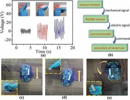
Fig.5.(a) The sensor attached on the hand bending at various angles and the corresponding piezoelectric responses.(b) The interacting process between human motion and a smart toy car.The smart toy car moved towards different directions when (c) punching,(d) tapping,and (e) bending motion were applied on the SF/PVDF piezoelectric sensor.
The mechanism of the piezoelectric device is that:Once the pressure is applied on the device,polarization changes in PVDF nanofibers,and a piezoelectric potential is built between upper and bottom electrodes.Forced by piezoelectric potential,free charges are induced to flow into the electrodes with an electrical signal in external circuit.Once the pressure release,the piezoelectric potential disappears,and the accumulated free charges flow back,during which a reverse electrical signal is detected in external circuit.To prove the output signal completely originate from the piezoelectric effect of the composite nanofiber,a‘switching polarity’ test was executed.The output signals obtained by forward and reversed connection have the same amplitude and opposite direction (Fig.S5),indicating that there is no triboelectric signal component and artificial interfere during the deformation of the device.The enhanced piezoelectric output of SF/PVDF NFs could ascribed to the increased PVDF crystallinity and β phase fraction.Meanwhile,the high mechanical Young's modulus of SF/PVDF (Fig.S6) could reinforce the stress transfer and makes the composite fiber suffer a large strain,which also benefits for an enhanced piezoelectric performance.Moreover,the SF could also provide the extra piezoelectric output due to its biological piezoelectric property[44].
The addition of inorganic nanofillers to PVDF can significantly boost the overall output performance of the piezoelectric devices,which many previous studies have proved [29,45,46].In the core-shell NFs,no inorganic nanofiller has been added;therefore,the as-prepared all-organic NFs are nontoxic and degradable,which create more possibilities for its application in wearable and biomedical fields.In addition,the enhanced piezoelectric output performance proves that the all-organic preparation strategy and the core-shell structure design are both feasible.
The effects of mechanical parameters (frequency and displacement)on the piezoelectric output performance of SF/PVDF composite NFs were investigated in Fig.3e and f.Under a fixed mechanical displacement of 5 mm,the output voltage of the piezoelectric device continues to increase with the increase of the frequency in the range of 0.5 Hz–2 Hz.It indicates that high strain rate could lead to fast accumulation and evanishment of piezoelectric charges.In Fig.3f,the output voltage increases as the displacement varies from 1 mm to 5 mm,when the mechanical frequency is fixed at 2 Hz.In this case,large displacement means large strain on the piezoelectric NFs,which results in much more piezoelectric charges.According to the output signals under different mechanical parameters,the piezoelectric device could be applied as a promising strain sensor.
With a rectifier bridge circuit in Fig.4a,the AC output generated by SF/PVDF piezoelectric device can be converted into DC output.As shown in Fig.4b,the power source after rectification can charge a 3.3 μF capacitor to 1 V within 200 s.Moreover,the 100 μF capacitor can be charged to 0.8 V in 800 s.Therefore,in this case,the SF/PVDF piezoelectric device can be hopefully applied as a sustainable power source for self-powered electronic devices.The amplified date insert in Fig.4b shows the charging voltage curve rise stepwise,suggesting that the capacitor stored the piezoelectric energy at each cycle of bendingreleasing process.To evaluate the durability of the SF/PVDF piezoelectric device,cyclic fatigue test was performed for a prolonged time(Fig.4c).The stable piezoelectric response shows no significant variation after more than 2000 cycles,demonstrating the excellent reliability and stability of the SF/PVDF piezoelectric device for practical applications.
Considering the high deformation adaptability and mechanical sensitivity,the SF/PVDF piezoelectric device was applied as a selfpowered sensor for motion monitoring.As shown in Fig.5a,the device was attached on the metacarpophalangeal joint to monitor different bending angles of the palm in real time.The response of the sensor stimulated by three different bending angles (≈30,60 and 90°) shows that the piezoelectric output amplitude of the self-powered sensor increases with the bending angle,resulting from the positive correlation of piezoelectric voltage to the tensile strain.The result demonstrates that the piezoelectric device can be efficiently applied as a sensitive strain sensor,which also exhibits its possibility to be assembled on the mechanical arm for smart sensing and monitoring[47].
Furthermore,to exhibit the multi-function of the device,the piezoelectric device was investigated as multifunctional generator and sensor in the human-machine interactive interface.Specifically,a smart car assembled with printed circuit boards(shown in Fig.S7)is controlled by a microcontroller,which is electrically connected with the flexible device and control the motor direction of the toy car.Fig.5b illustrates the diagram of this interacting process.In this intelligent system,different command codes are triggered by different thresholds of the electrical signal amplitude that preset in the programmable microcontroller.As the piezoelectric device could generate various amplitude output under different stimulation,the device could directly control the movement of the car.As can be seen in Fig.5c-e and Video S1,the car executes the command of moving forward,moving back and rolling under the stimulation of punching,tapping and bending on the piezoelectric device.Due to the different strain applied by these three movements on the device,each stimulation triggers a command code to the car,thus leading to the achievement of the piezoelectric device in the successful application of human-machine interaction.
4.Conclusion
In summary,SF/PVDF composite NFs with a core-shell structure have been successfully fabricated through a simple coaxial electrospinning technique.The intermolecular interaction between SF and PVDF chain enhances the formation of β phase PVDF with a high proportion.The flexible device assembled by SF/PVDF electrospinning mat exhibits a high voltage of 16.5 V with a current of 290 nA at a SF content of 14 wt%.The generated voltage is more than 6-fold of the value of pure PVDF NFs.In the durability test,the piezoelectric composite NFs shows an excellent stability over 2000 period cycles,without any performance decline.Furthermore,the piezoelectric device can be successfully applied as a self-powered sensor to monitor human joint movements,and control a smart car movement in the human-machine interaction.The result demonstrates that the coaxial electrospinning technique is a feasible approach to fabricate core-shell NFs with high piezoelectric performance,and the SF/PVDF composite NFs based flexible devices hold great potential in energy harvesting and sensing.
Declaration of competing interest
There are no conflicts to declare.
Acknowledgements
This study was supported by Medical Engineering Cross Research Foundation of Shanghai Jiao Tong University(YG2021QN63).
Appendix A.Supplementary data
Supplementary data to this article can be found online at https://doi.org/10.1016/j.nanoms.2021.07.008.

- Namo Materials Science的其它文章
- Preface of “Trends in Nanomaterials and Nanocomposites:Fundamentals,Modelling and Applications”
--Festschrift in honor of Prof Yiu-Wing Mai's 75th birthday - A comparative study of 85 hyperelastic constitutive models for both unfilled rubber and highly filled rubber nanocomposite material
- On mechanical properties of nanocomposite hydrogels:Searching for superior properties
- Ultra-transparent nanostructured coatings via flow-induced one-step coassembly
- VN nanoparticle-assembled hollow microspheres/N-doped carbon nanofibers:An anode material for superior potassium storage
- Molecular dynamics study on mechanical behaviors of Ti/Ni nanolaminate with a pre-existing void