
Health Monitoring of Induction Motor Using Electrical Signature Analysis
2022-08-08 05:48ABDULRaufMUHAMMADUsmanAHMADButtZHAOPing
ABDUL Rauf, MUHAMMAD Usman, AHMAD Butt, ZHAO Ping(赵 萍)
1 College of Information Science and Technology, Donghua University, Shanghai 201620, China 2 Department of Electrical Engineering and Technology, University of Engineering and Technology, Lahore 54890, Pakistan
Abstract: Induction motors have been widely used across industry, particularly with smaller loads and fixed speed services. Existing works focus on fault detection of induction motors without considering the shutdown time and production in industry. Therefore, this work aims to monitor the health conditions of the induction motor continuously through electrical signature analysis(ESA). The proposed technique is capable of predicting different kinds of faults, i.e., rotor faults, stator phase imbalances, and supply cable faults at early stages. Moreover, ESA in real time is implemented. Thereafter, these current spectra were analyzed in frequency domain and compared with healthy current spectra. Performance evaluation is implemented by observing these spectra under different faulty conditions. A comparative study is made and analyzed through MATLAB simulations.
Key words: induction motor; electrical signature analysis(ESA); fast Fourier transform(FFT)
Introduction
Electric motors are one of the main components of today’s process industry.Performance of the induction motor has a direct effect on production line of industries[1].Therefore, the operators as well as the manufacturers of motor industries are working to develop a system that pre-determine the faults in motors before the complete failure as well as to reduce the maintenance cost and unscheduled failure.The sudden fault results in production loss and financial loss.The pre-detection of motor health or pre-determination of faults in motors provide an opportunity for maintenance of motors during schedule routine without loss in production as a result of increasing in performance and efficiency of plant[2].
The fault diagnosis and protection of electrical motors is an old concept.At first, the engineers and operators of electrical motors used the simple and easy method of protection such as over current, overvoltage, and earth-fault to ensure safe and reliable operation of motors.Despite of that, the performance of the motors grew increasingly complicated, the fault diagnosis became very essential[3].
Nonlinear behavior is one of the biggest challenges in the study of induction motor fault analysis.Many previous works also reported, but incipient fault detection was still an open issue to develop a system that would efficiently pre-determine the fault or monitor the health of the motor[4].The electrical signature analysis(ESA)is one of the most efficient technique to monitor the health of the motor.Frequency domain analysis is used to compare harmonic spectra with healthy spectra of the motor to determine the health of the motor[4].
This document aims to show and explain the process of designing, building, programming and finally testing overall designed system for induction motor in real-time implementation.New methods have been developed which are now being used by the operators, and research is being continued with the development of new and alternative online diagnostic techniques.
This paper has been organized as follows.The methodology in section 1 and section 2 give an overview of the system implementation.Section 3 deals with the performance evaluation and the conclusions are presented in section 4.
1 Methodology
This project involves the examination of electric current and voltage around any of the one phase or three phases of power supply.Electric current can be measured with the help of current transformers assembly connected with hall effect sensors.The current signal is used for health conditioning of induction motor.Data acquisition(DAQ)digitalizes the signal to permit the time and frequency spectra for analysis.The time varying current signal is then transformed into frequency domain through fast Fourier transform(FFT).Then harmonics created at different faults are investigated through these FFTs.Consequently, this helps to identify the faults type in the system.
Electrical signature is the real-time waveform of voltage and current using Hall effect sensors and DAQ equipments.This paper use analogue input pin to take signal from Hall effect sensors.DAQ is used to generate these waveforms/signatures in real time.Then the FFT of these waveforms is taken in order to analyze the frequency domain and get its harmonic order.This signature is used as a standard for further experimental analysis.Afterwards, the signature is tested at the motor’s steady-state and unloaded conditions.
Two single-phase induction motors were used in this project.These motors were used in submersible pumps which both had the same nameplate, so this paper used one motor as a standard motor to get the healthy signature, by the way, two motors have approximately similar healthy signals with a minor difference.
The faults were introduced in the induction motors.Then, their voltage and current waveforms were examined, and get their Fourier transforms.These waveforms and their obtained Fourier transforms were compared with the healthy ones.There is a substantial discrepancy among these waveform bands compared to the motor faults that have been added.
After all, it is very easy to find out faults in motors, but it can also predict which kind of fault it is.Therefore, this is also very helpful in the diagnostic analysis of the motor.One of the advantages of this method is that it doesn’t stress on motors mechanically as it doesn’t measure the fault physically[5].
1.1 Faults in induction motor
The faults in an induction motor are categorized as rotor faults, bearing faults, eccentricity faults, and stator faults.This survey indicates that failure in induction motors is dominated by stator faults, and bearing faults with rotor faults are less frequent.
As shown in Fig.1, different surveys of fault probability in induction motor reveals that around 41% of faults in induction motors are bearing faults[6-7], where stator faults are dominated after bearing faults around 37%, other faults including rotor faults and eccentricity faults have only 10% and 12%, respectively[5].
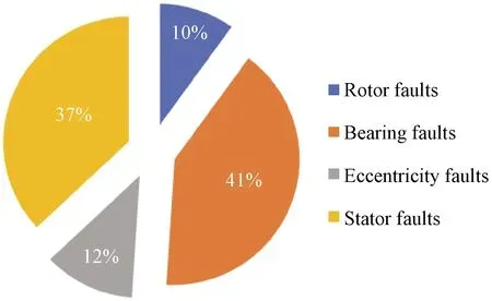
Fig.1 Various faults probabilities in induction motor
In order to pre-detect the faults in induction motors, many techniques are used such as current signature analysis, vibration monitoring, and electromagnetic filed monitoring[8].
1.1.1Rotorfaults
The main cause of rotor faults in the induction motor is due to rotor field winding short circuiting, rotor bar damage, and rotor end-rings broken.The rotor faults can cause sparking and overheating in the motor.On the early stage, broken rotor faults can be detected by ESA.The stator current frequencies are given by
(1)
wherefris the broken rotor bar frequency,fsis the input supply frequency,Sstands for per unit slip, andPis the number of poles whileK= 1, 2, 3.The motor rotor fault causes increment in motor current with no load, eventually it decreases in the motor efficiency[9].
1.1.2Bearingfaults
Bearing faults are one of the critical components of the induction motor, and they are more difficult to be detected than rotor faults.Bearing faults in the induction motor are mechanical faults which cause a change in the stator current spectrum[7].
(2)
and
f=|fs±(m×fb)|,
(3)
wherefbis the bearing fault frequency,Nbis the number of balls in a bearing,ωis the shaft speed or running speed of the motor,ddenotes the bearing ball diameter,Dis the pitch diameter,αis the contact angle of the bearing,fis the original frequency,andmrepresents integer numbers.
1.1.3Eccentricityfaults
This fault represents a condition when the air gap distance between the rotor and the stator is not uniform.There are two types of abnormal air gaps.These two types of gaps are static air gap and dynamic air gap.In case of static air gap there is fixed air gap between the rotor and the stator, while in case of dynamic eccentricity faults, the air gap does not follow the fixed rotor motions[10].To identify the air gap eccentricity by the electric spectrum techniques, a 0.1 mm copper strip is used to cause static eccentricity.Then the motor runs at its rated speed.These frequencies are visible in frequency spectra.
(4)
whereferefers to the eccentricity frequency,fgrefers to the electrical supply(grid)frequency,Rrefers to the number of rotor bars,nd=±1, andnws= 1, 3, 5, 7.
1.1.4Statorfaults
The fault in stator winding of the induction motor is analyzed by stator current spectra.This can be explained by
(5)
wherefrefers to the stator fault frequency,fsrefers to the supply frequency,Nrrefers to the rotor speed,Srefers to the motor slip, andmrefers to the harmonic order.
1.2 ESA
ESA is the procedure to get the motor current and voltage to monitor the health of the motor.Figure 2 shows the basic principle of ESA.
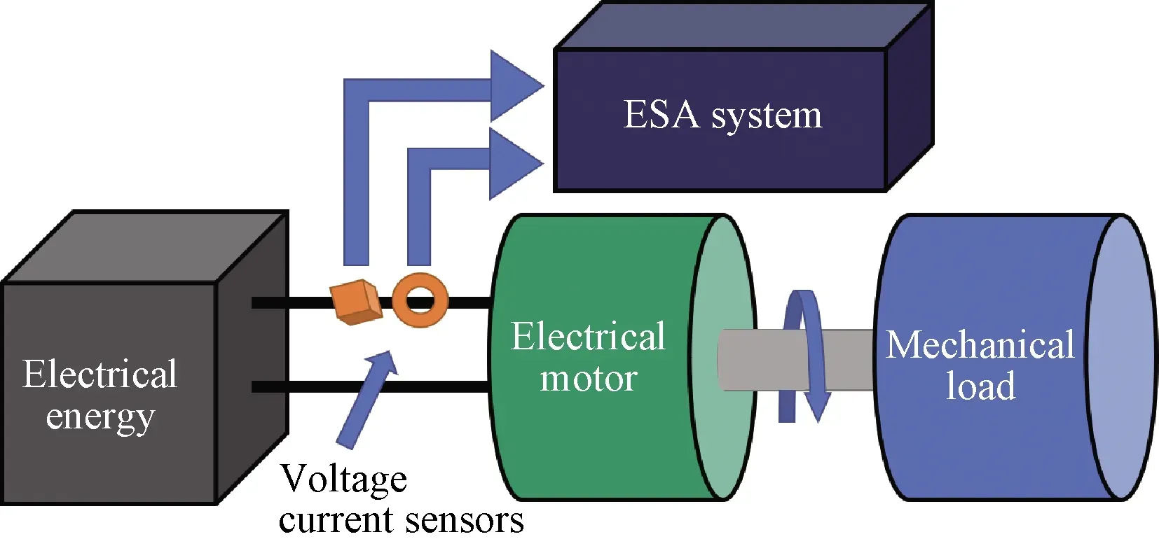
Fig.2 Basic principle of ESA
ESA can monitor the health of the motor without disturbing the basic operation of the motor.In this technique, the current on any phases is measured by the current transformer.The current is then transformed into frequency spectra to analyze the fault and compare it with the healthy spectra[11-16].
After measuring the current around any phase or on three phases with the help of current transformer.The analogue data are converted into digital data with the help of data acquisition device DAQ USB-6009(National Instruments, USA), which will help us to analysis the spectra.The time varying signal is then transformed into frequency domain using FFT algorithm.
He left that to her. She learned sign language as quickly as possible. Her husband wasn t interested. When he talked to the boys, he treated them like they were dogs, patting them on the head, barking out a word or two.
Motor current waveforms are recorded in time domain.Then the signal is converted analog to digital.Visualization of the motor current waveform is typically analyzed using spectral analysis methods.If signal is represented byX(t)asNdiscrete samples, it can be represented as phase shiftsθiand a sum ofNsinusoidal components of frequenciesωi, and described by
(6)
(7)
wherefsis the sampling rate of signal,Aorefers to the DC off-set,ωiis the rotational frequency.We can express same signal in the form of sines and cosines, given as
(8)
whereaiandbiare constants, we can determine their values by Fourier transforms given as
(9)
(10)
(11)
whereAiis the amplitude of the frequency components.
For frequency domain analysis of a signal, FFT is a common and easy method.It’s an efficient version of discrete Fourier transforms that reduces computational complexity fromO(N2)toO(NlogN).FFT is suitable for steady state signals[17].
2 System Implementation
Faults analysis of the induction motor experiment involves two steps: taking of healthy signatures, and taking of faulty signatures(signatures after introduction of faults).
Figure 3 shows the overall flow diagram of the real-time hardware model.The Hall effect senor will get the current value of the single phase motor and feed it to DAQ USB-6009 for real-time results in LabVIEW.
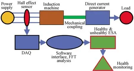
Fig.3 Flow diagram of ESA analysis
The theoretical implementation of whole system is shown in Fig.4.In MATLAB, Powergui module is used to perform FFT analysis.Powergui is a graphical user interface which is used for different analyses on continuous signals.The supply frequency is 60 Hz that is provided to single phase capacitor start induction motor.
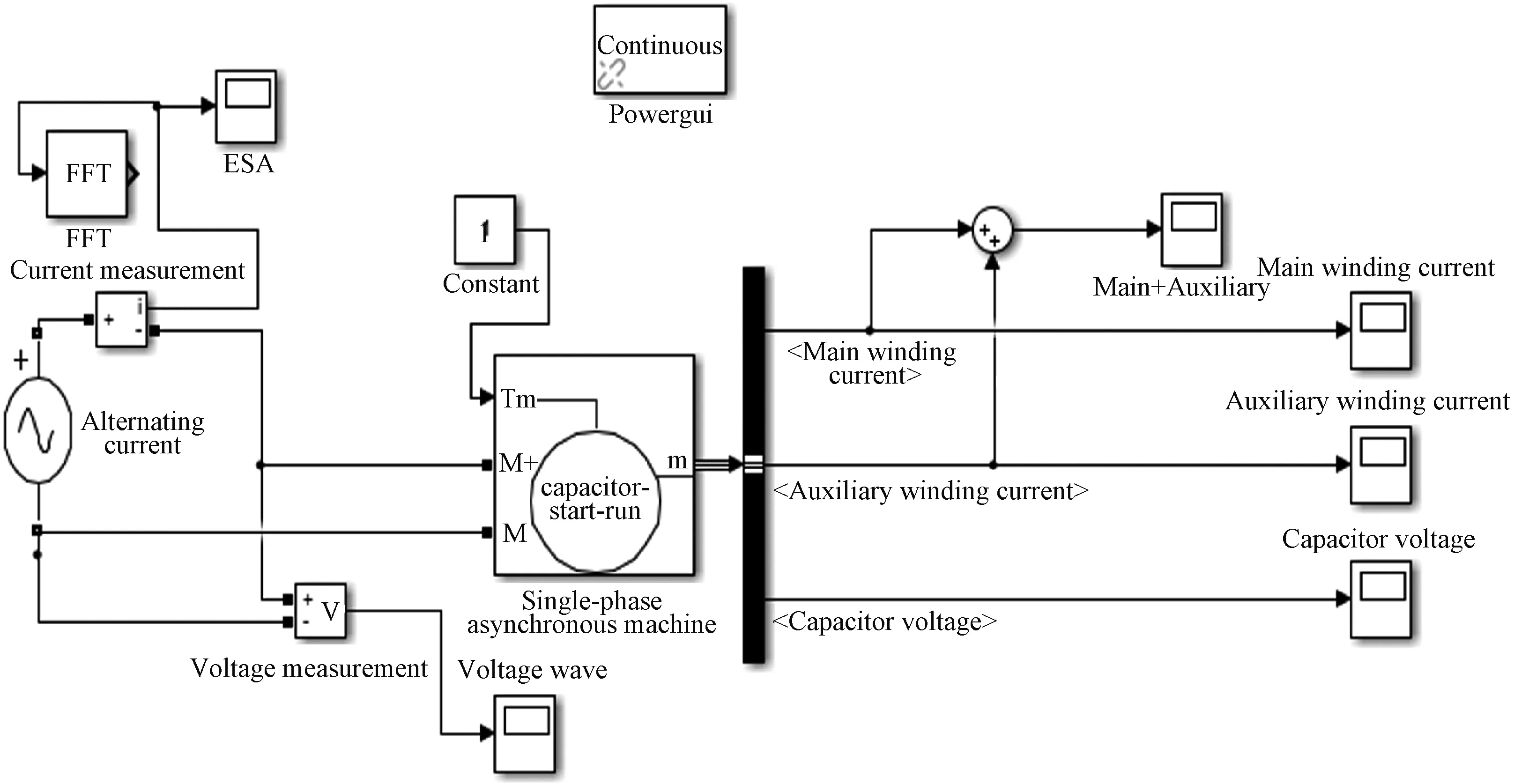
Fig.4 MATLAB simulation of induction motor
3 Performance Evaluation
The real-time implementation of hardware prototype is implemented in LabVIEW.Electrical signature is the real-time waveform of current and voltage using the Hall effect sensor and DAQ USB-6009 equipment.Analogue I/O pin is used to take signals from Hall effect sensor.DAQ USB-6009 is used as a data acquisition center and generates these current signatures in real time.We get FFT of these waveforms in order to analyze frequency domains and get its harmonic order.This signature is used as a standard for further experimental analysis.We get this signature under steady state and unloaded conditions.In this scenario, all the motors having the same name plate under the same conditions(the same production batch)will have the same signature.So, the companies can use this approach to check if there is any fault in their motors by making it as motors standard and get its healthy signatures and compare it when they get faulty.This paper proves that this process is cheap and easy to find out any kind of faults and also can give insight about a new motor waveform which is different from the standard one.
The FFT results of real-time implementation of hardware prototype of all faults described through figures and tables in the following subsections.
3.1 Healthy motor
Figure 5 and Table 1 show that the motor works normally without significant differences in harmonics components(f1,f3,f5,f7,f9,f11).
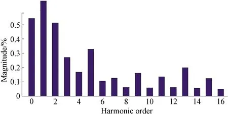
Fig.5 Harmonic waveform of healthy motor
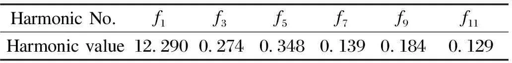
Table 1 Harmonic levels for healthy conditions
The total harmonic distortion(THD)of the cable resistance faults signature is 0.88% which is given by MATLAB.
(12)
3.2 Analysis of rotor faults
In this research, one induction motor is dedicated to study rotor faults.For the introduction of rotor faults, we used grinder machine and grinded three bars of the rotor.Grinded portion depth reaches nearly 2 mm.this portion used to disturb the eccentricity and magnetic flux around the rotor.Due to this fault, the resistance of the rotor increases compared to previous healthy conditions(shown in Table 2 and Fig.6).
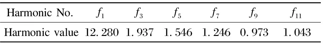
Table 2 Harmonic levels for rotor faults conditions

Fig.6 Harmonic waveform of rotor faults
(13)
The THD of the rotor faults signature is 4.19% which is given by MATLAB.
3.3 Starter winding faults
Figure 7 and Table 3 show that the DC off-set in case of starter faults increases.
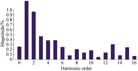
Fig.7 Harmonic waveform of starter winding faults
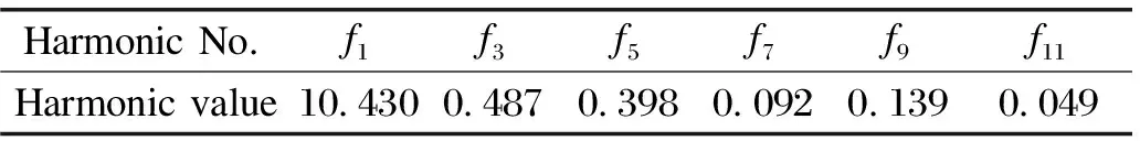
Table 3 Harmonic levels for starter winding faults conditions
The THD of the starter winding faults signature is 1.37% which is given by MATLAB.
(14)
3.4 Supply cable faults
Figure 8 and Table 4 show the DC off-set in case of cable resistance faults with harmonic components.

Fig.8 Harmonic waveform of supply cable faults
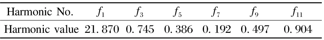
Table 4 Harmonic levels for supply cable faults conditions.
The THD of the supply cable faults signature is 1.62% which is given by MATLAB.
(15)
This paper uses the fault signature from motor supply current.On the contrary, other studies used two frequently applied approaches such as vibration analysis(VA)and motor circuit analysis(MCA)[1-6].On the one hand, VA needs an accelerometer sensor which is put on the motor, the sensor is associated with a data acquisition device to monitor vibrations at bearing or shaft assemblies[1].On the other hand, the MCA measures the insulation resistance in order to check the integrity of the insulation in induction motor, which demands the motor to be turned off[9].Therefore, the ESA requires only access to motor current, making it a low-cost and better solution for the induction motor health monitoring.Furthermore, a standalone device can be used to perform the ESA.The comparison of healthy and faulty conditions of induction motor is given in Table 5.
It is apparent from Table 5 that triplenf3harmonics have a significant increase with the induction of each fault in the induction motor.We can infer, there is an increase inf9andf11harmonics(abovef7harmonics)as compared to healthy conditions which reveals that there exists a fault in supply cable of the induction motor.Similarly, the significant increase inf5andf3harmonics(belowf7harmonics)leads us to the existence of faulty conditions in starter winding faults.Furthermore, the increase in all harmonic values with respect to healthy conditions show the occurrence of rotor faults.The comparison of THD under healthy and faulty conditions is given in Table 6.
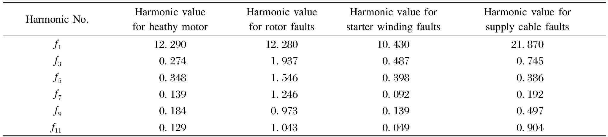
Table 5 Comparison of harmonics under healthy and faulty conditions

Table 6 Comparison of THD under healthy and faulty conditions
The study analyses only two types of induction motor faults such as rotor faults and starter winding faults using FFT analysis, and only observe change in FFT and THD trends with the increase of harmonic order within a single fault[6].Another study used ESA analysis to monitor stator winding faults only in brushless direct current motor(BLDC)[4].Our study extended the use of ESA for induction motor as well.In addition to previous study[6], current study using ESA technique analyzes supply cable fault as well.This study not only analyzes 3 kinds of induction motor faults but also compares them with healthy motor conditions.Similarly, current study can detect the health condition of a motor with a small variation in THD as compared with the previous study that needs a large variation in THD[6].THD for broken rotor faults and stator winding faults was 101.52% and 59.97%,respectively.For current study THD variations are very little as compared to other study as shown in Table 6[6].
4 Conclusions
Induction motors are backbones in process system, and thus the maintenance practice in maintaining the reliability of the induction motor is a key factor in making the process system reliable.Meanwhile, the ESA is one of the powerful techniques to aid the maintenance practice on a motor through prior fault detection.Therefore, this work proposes a MATLAB model for conducting FFT analysis on different fault frequencies which is also known as side-band frequencies.It is clear from the experimental results that when the motor is subjected to a fault, harmonics change appears in the power system, which can be observed by the spectrum of the current.These signatures are useful to identify the faults in a system.The parameter such as THD shows the significant variations to determine the type of faults.Finally, it has been identified that prognostic study can help the industry to manage the shutdown of power and the production efficiently, which in return leads to more revenue.
 Journal of Donghua University(English Edition)2022年3期
- Journal of Donghua University(English Edition)的其它文章
- Three-Dimensional Model Reconstruction of Nonwovens from Multi-Focus Images
- Toughness and Fracture Mechanism of Carbon Fiber Reinforced Epoxy Composites
- Three-Dimensional Metacomposite Based on Different Ferromagnetic Microwire Spacing for Electromagnetic Shielding
- Blockchain-Based Architectural Framework for Vertical Federated Learning
- Optimal Control of Heterogeneous-Susceptible-Exposed-Infectious-Recovered-Susceptible Malware Propagation Model in Heterogeneous Degree-Based Wireless Sensor Networks
- Enhanced Arsenite Removal Using Bifunctional Electroactive Filter Hybridized with La(OH)3