
Single-beam leaky-wave antenna with wide scanning angle and high scanning rate based on spoof surface plasmon polariton
2022-10-26 09:46HuanJiang蒋欢XiangYuCao曹祥玉TaoLiu刘涛LiaoriJidi吉地辽日andSijiaLi李思佳
Chinese Physics B 2022年10期
关键词:刘涛
Huan Jiang(蒋欢) Xiang-Yu Cao(曹祥玉) Tao Liu(刘涛)Liaori Jidi(吉地辽日) and Sijia Li(李思佳)
1Information and Navigation College,Air Force Engineering University,Xi’an 710077,China
2Shaanxi Key Laboratory of Artificially-Structured Functional Materials and Devices,Air Force Engineering University,Xi’an 710051,China
Keywords: spoof surface plasmon polariton(SSPP),leaky wave antenna,wide scanning angle,high scanning rate
1. Introduction
Improving sensor detection and determining the accuracy and effectiveness of the target is a perennial challenge in radar applications.[1–5]The scanning-rate(SR)represents the sensitivity of radiation direction with frequency change. We prefer to design a leaky-wave antenna, which takes advantage of a narrower bandwidth to cover a larger scanning range. In recent years,the characteristics of LWAs based on the SSPP TL,with its simple structure, frequency scanning characteristics,and compatibility with planar circuits, have attracted significant attention.
The surface plasmon polariton (SPP) is a mixed excited state, propagating along the medium-metal interface generated during the interaction of light with a metal, and exhibiting a highly confined surface wave in the medium outside the metal.[6]The spoof surface plasmon polariton (SSPP) is the analogous extension of the SPP concept in the low-frequency band. When electromagnetic (EM) waves interact with the artificial EM medium, a kind of hybrid surface EM mode is generated at the medium interface. Its characteristic subwavelength,enhancement of the local field,and nonlinear dispersion curve offer significant application value in the design of antennas,[7]filters,[8]TLs[9]etc.[10–19]
The EM wave propagates in the form of a slow wave in the antenna, and the propagation speed of the slow wave is below that of an EM wave in free space. Slow waves cannot radiate into space directly. However,when an EM wave’s propagation speed is higher than that in free space,it radiates in the form of a fast wave. To create this radiation effect in the antenna requires a progression from slow wave to fast wave.However,the conversion of a slow wave confined in the SSPP TL into a fast wave, so as to generate radiation of the frequency scanning beams, represents a technical problem with regard to SSPP-based antennas,which must be resolved. The first method involves periodically modulating the SSPP TL,so that EM waves are released into the fast wave region.[10–12]The maximum scanning angle that can be achieved in this way is 123°.[11]In view of the limitation whereby general SSPP LWAs can only radiate linearly polarized waves,Ref.[12]proposed that the SSPP unit could be rotated 45°,and the surface impedance could be controlled by changing the depth of the groove,creating an antenna adaptable to any type of polarization mode.
To realize the leaky-wave, the second method introduces periodic perturbations by periodically arranging patches around the TL,which couple the EM waves to the patches to form a fast wave pattern matching the spatial waves for beam scanning in vacuum. In Ref.[13],the antenna was composed of two rows of circular patches placed on both sides of the SSPP TL,covering an angle of 83°from 9.2 GHz to 16 GHz.In Ref.[14],an antenna based on the glide-symmetry Goubau line covers a range of 145°with high-order harmonic radiation within 6.3% bandwidth, and achieves a very high scanning rate. However, this antenna fails to radiate efficiently, with an average radiation efficiency of only 26%. In the design of LWAs with a high scanning rate, there is always a trade-off between scanning rate and efficiency.
There are other methods of achieving frequency scanning radiation. In Ref. [15], an antenna based on a substrate integrated waveguide(SIW)realizes 35°beam scanning in a narrow band of 3%. However, due to the symmetry of its design structure, this antenna also exhibits the stop-band problem common to traditional LWAs. This inability to realize broadside radiation is a key limitation of continuous wideangle scanning. In Ref. [16], the SSPP-based antenna used periodic holes etched in the CPW to generate waves in the higher-order SSPP mode,capable of covering a wide scanning angle of 129°,while the low scanning rate caused by an operating bandwidth of 11.7–50 GHz is not expected. Therefore,it is necessary to design a compact antenna with a wide scanning angle,a high scanning rate,and high radiation efficiency.
In this paper, a single beam SSPP-based LWA is proposed, whose compact structure can readily be fabricated for practical applications. The stop-band effect is suppressed,and the scanning range is enlarged.By adjusting the periodic modulation,the frequency band of the antenna tends to be near the cutoff frequency, exhibiting a higher scanning rate. The antenna achieves a high scanning rate of 12.12,and a efficiency of 81.4%. Its scanning angle of 176°represents the largest among antennas of the same type, and its average gain is as much as 10.9 dBi in the working frequency band. This proposed antenna based on SSPP demonstrates outstanding performance.
2. Antenna structure and design
The geometrical configuration of the proposed leakywave antenna is shown in Fig.1. The SSPP TL is introduced on the middle layer. A series of circular patches are placed on the top and bottom layer as radiating elements. The layers are filled with F4BM-2, where the dielectric constant isεr=2.65,the loss tangent is tanδ=0.001,and the thickness of the single-layer medium isth=1 mm. The overall size of the antennaL×W=35.6 mm×400 mm.
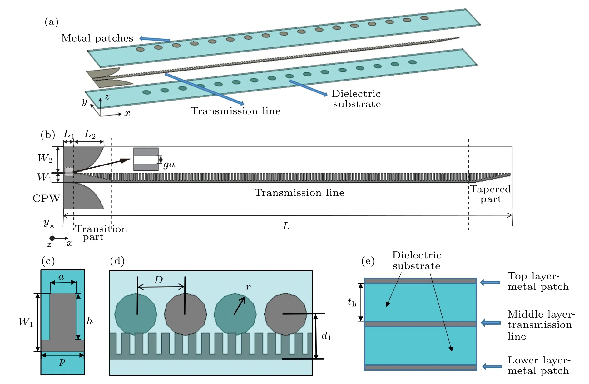
Fig.1. Geometry of the proposed LWA.(a)Perspective view. (b)Feeding layer. (c)TL unit. (d)Radiating elements. (e)Multilayer layout.
In the middle layer, the left-hand end is fed via a coplanar waveguide (CPW) measuringL1=10 mm. The smooth groove gradient structure is connected with TL to match the input impedance,reduce reflections,and increase the efficiency of the antenna radiation.
The exponential-shaped ground sides are conducive to an efficient matching in broadband asy=f(x) =C1eαx+C2,whereα=0.1,C1=W2/(eαL2-1),C2=-W2/(eαL2-1)+ga+W1/2 and the coordinate origin is set at the beginning of the transition. Reference [17] shows that this tapered structure forms a good bridge with which to connect the CPW,with 50 Ω impedance and SSPP TL in the microwave frequency, converting the guided waves to the slow wave mode bounded in the SSPP TL,and demonstrating high efficiency in the broadband.
In the SSPP TL section,periodic sub-wavelength grooves are arranged in the metal microstrip lines with a period ofp=2.5 mm, a duty cycle ofdc=a/p=0.6, and a groove depth ofh= 4 mm. The gap,ga= 0.28 mm, and width,W1= 5 mm, of the central strip are designed to achieve a 50 Ω impedance.The antenna adopts a single-port and tapered structure at the end.
In the radiation section, circular patches are placed near the SSPP TL. The front and rear backplanes are composed of circular patch arrays staggered in front and back. We set the period of single-side patch arrays,D, at 9.38 mm, and the distance between the patch center and the central axis atd1=6 mm. The radiusris set at 4 mm.
3. Principle and analysis
3.1. SSPP TL analysis
We were able to confirm that periodic metallic grooves allow the surface plasmon mode to propagate at microwave frequencies. Figure 2 shows dispersion diagrams of singleand double-layer medium units with varying depths of groove.It is evident that with an increase in the frequency of the dispersion curve,βalso increases, and gradually deviates from the light,whereβrepresents the propagation constant. Closer to the asymptotic frequency, the alteration in the propagation constant is more dramatic. The figure shows that in contrast with the single-layer unit,double-layer units have a lower cutoff frequency, enabling the double-layer SSPP TL to confine EM on the surface more strongly than the single-layer TL.Moreover, the deeper the metal groove, the lower the cutoff frequency of the dispersion curve becomes. The depth,h,and structure of the model represent two important factors affecting the dispersion characteristics of the unit. We selected a dual-layer element withh=4 mm to modulate the cutoff frequency at around 10 GHz.
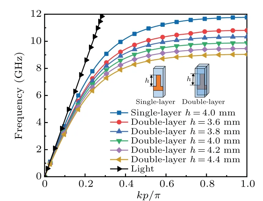
Fig.2. Dispersion curves of the unit cell in SSPP TL.
In order to illustrate the characteristics of the TL,E-field distributions on double-end TLs at different frequency points in thexozplane were simulated, as shown in Figs. 3(a) and 3(b). EM waves were transmitted through the TL at 8 GHz and 9.5 GHz to the other port. When the frequency is set to 10.5 GHz,it is clear that EM waves are strictly confined to the gradient part. TheS-parameter in Fig.3(c)shows that the cutoff frequency of TL is 10 GHz. Beyond the cutoff frequency,energy cannot be transmitted to the other end,clearly demonstrating the low-pass properties of TL.

Fig.3. Transmission characteristics of the SSPP TL.(a)Structural diagram of transmission line. (b) E-field distributions of the SSPP TL at 8 GHz, 9.5 GHz and 10.5 GHz in the xoz plane. (c) Simulated Sparameters of the SSPPs TL.
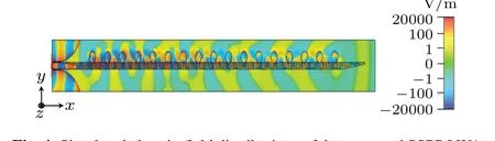
Fig.4.Simulated electric-field distributions of the proposed SSPP LWA at 9 GHz.
Leaky-wave antenna usually adopts a dual-port structure to ensure that the EM waves transmitted to the end of the antenna can be absorbed,so that the reflected wave cannot affect the direction of radiation. The structure adopts a single-port and a tapered structure at the end,as shown in Fig.1(b). Such a structure causes the SSPP wave mode to shift to the space wave mode, such that a small amount of EM waves reaching the end are radiated to reduce the impact of reflections on the original feeder electric field. In Fig.4,we note that the energy along the TL decreases significantly along thex-direction.
3.2. Radiation element analysis
In order to radiate EM waves and form LWAs based on an SSPP TL,we need to disturb propagating surface waves by periodically placing radiating patches near the SSPP TL.If the radiation efficiency is high enough, the matching load can be removed,which not only reduces the antenna size but also decreases the influence of the end on the far field pattern of the patch arrays,and improves the realized gain.
The radiation element is a circular patch with isotropy,and the resonant frequency of the element is primarily determined by its size.Radiation efficiency can be improved by setting the element resonant frequency within the working bandwidth, so the radiusris set at 4 mm, based on the following expression:

wherek11represents the eigenvalue of the TM11mode,cis the velocity of the light in vacuum,andfis the center frequency.
In Fig.1(d),an interleaved array of patches balances the front and rear of the far-field pattern so that the main radiation lobe can scan in thexoyplane of the antenna. Since the distance between front and rear is relatively close,there is no obvious deviation for the periodDof periodic disturbance;placing patches on the upper and lower surface facilitates better coupling with the energy on the TL.
Methods such as mode balance,[18]impedance matching,[19,20]and loading asymmetric radiators[18,21,22]effectively suppress the open stop-band(OSB)effect.Moreover,as described in Ref.[14],the asymmetrical structure also helps to suppress the stop-band. There is no OSB problem in the antenna structure proposed in this paper. The beam-scanning characteristics of the antenna are realized via the feed phase difference in the SSPP TL. If we wish to realize radiation in the broadside direction, we need the patch to couple energy,and the adjacent phase difference is zero. Since the SSPP TL has different wave numbers at different frequencies,there must be a specific frequency point to realize zero phase difference between two adjacent patches. Once there is no phase difference between the patches,the radiation beam can access the broadside direction.
The asymmetric structure of the antenna effectively inhibits the generation of the stop-band, thereby removing the discontinuous scanning angle in the broadside,which is common in many other LWAs. The gap,d1, between the patches and the TL only affects the coupling energy from the TL.These radiating patches couple EM waves from the SSPP TL through periodic disturbances, and radiate them into free space.
3.3. Analysis of beam scanning characteristics
The propagation constant of EM waves guided by a slowwave structure is larger than that for a free space wave(βx >k0),and does not radiate.The design of the antenna is based on the principle of periodic disturbance,[10]which introduces an infinite number of spatial harmonics into the periodic traveling wave.
It is assumed that the EM waves propagate in thexdirection. The fundamental mode is a slow wave(β0>k0). However,there is always a certain harmonic(usually the-1stharmonic)producing fast-wave radiation(-k0<βx <k0).
On this basis, the propagation constant along thex-axis can be expressed as
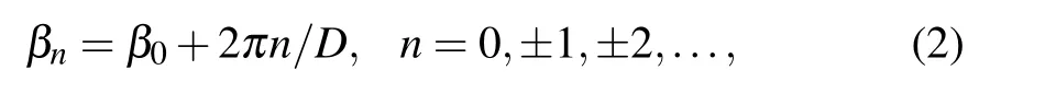
whereDis the length of the periodic disturbance, andβ0is the propagation constant in the fundamental mode. In order to achieve efficient frequency scanning, we generally adopt a space harmonic ofn=-1 to realize beam scanning.
The deflection angle and propagation constant of the antenna satisfy the following relations:

wherek0is the propagation constant in free space,θis the included angle between beam direction and+zaxis,andβxrepresents the propagation constant of the corresponding space harmonic.
Figure 5(b) shows the dispersion curves of the periodic element of the antenna along with the distribution of multiple harmonics. In the figure,A1(A2),B1(B2) andC1(C2) represent the backward endfire, broadside radiation and forward endfire of harmonics,respectively:
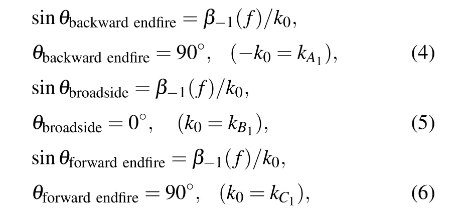
whereβ-1(f)represents the dispersion curve of phase change with frequency change in the-1stharmonic mode.
The dispersion characteristic data obtained via simulation is discrete. When deriving the formula, the fitted continuous curve is more conducive to the operation of the relationship between multiple harmonic dispersion curves. The reference values of key experimental parameters obtained by this operation are conducive to the design of the antenna. The frequency band of the-1stharmonic radiation mode can be controlled by adjusting the size of theDparameter.
In order to more accurately calculate the disturbance cycleDvalue corresponding to the-1stharmonic radiation mode, MATLAB is used to fit the dispersion curve; the resulting expression is as follows:

wherea1=1.824×10¹⁹,a2=2.474×10⁵,b1=23.61,b2=52.75,c1=2.217,c2=17.76.
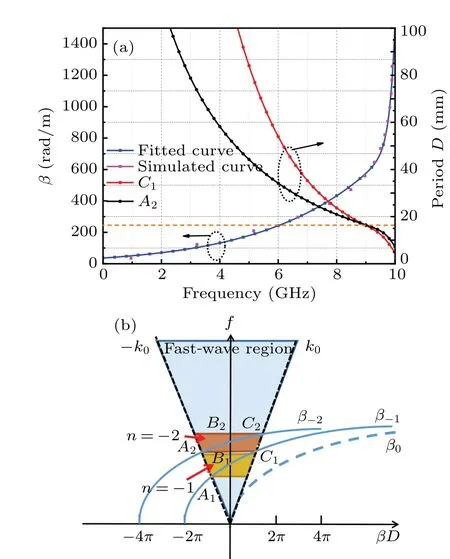
Fig. 5. Simulated results for harmonic dispersion and single-beam radiation conditions. (a)Diagram of fitting results and single-beam radiation conditions. (b)Harmonic dispersion curves of periodic elements.
The fitting curve in Fig. 5(a) is in good agreement with the simulation curve. Thenstharmonic radiation is expected to concentrate energy in a single lobe,which serves to improve the gain of the main lobe:
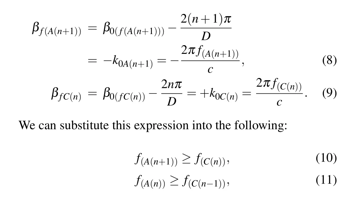
whereβf(A(n+1))represents the propagation constant of the(n+1)stharmonic backward endfire,andβf(C(n+1))represents the propagation constant of the (n+1)stharmonic forward endfire. Here,k0C(n)andk0A(n)represent the corresponding phase constant values ofC(n)andA(n),respectively.
In Fig.5(a),the radiation condition of the-1stharmonic single beam can be obtained by substituting the fitted expression (D ≤16.8 mm). By substituting the fitting curve expression,the relationship betweenDparameter and operating bandwidth can be calculated,which is also convenient for antenna design. The fitted continuous curve enables a more accurate prediction of the relationship between beam direction and frequency.
Different frequencies correspond to different propagation constants on the SSPP TL, resulting in different phases between the coupled patch arrays, culminating in the formation of different radiation directions in the far field. The expression obtained via fitting result in a more formulaic calculation,which makes the antenna radiation direction more accurate. By substituting into Eqs.(2),(3),and(7),we obtain frequency points corresponding to the theoretical radiation of the antenna. Theoretically,the frequency of backward,broadside,and forward endfire are 8.3 GHz, 9.1 GHz, and 9.6 GHz, respectively,while the actual results are 8.2 GHz,9.2 GHz,and 9.6 GHz, respectively. The theoretical calculation results are in good agreement with the simulation results,which demonstrate that the dispersion curve expression obtained by the fitting curve can be fitted with the calculation results.As a result,the expression plays a guiding role in adjusting the working bandwidth of the antenna, and predicting the relationship between radiation direction and frequency. The fitting result further validates the feasibility of Eq.(7),and the validity of these equations is convenient in terms of determining the operating band for given structural parameters.
3.4. Analysis of high-frequency scanning rate implementation
In Fig. 6, the first shifted dispersion curve has a lower frequency and a larger slope change,while working in a wider bandwidth.The second shift has a higher frequency point with a smaller slope change,and backward to forward scanning can theoretically be realized.

Fig.6. Scanning rate comparison of two different momentum compensations for leaky-wave radiation.
Since the scanning rate of leaky-wave antennae is defined as the beam-scanning range divided by the frequency bandwidth(BW),a higher scanning rate can be realized by adjusting the phase shift close to the asymptotic frequency,resulting in a smaller-slope dispersion curve. By adjusting theDvalue,the operating frequency tends to be asymptotic,so that the antenna has the property of realizing wide-scanning-angle in a narrower bandwidth. In this way, the scanning rate (SR) can be improved.
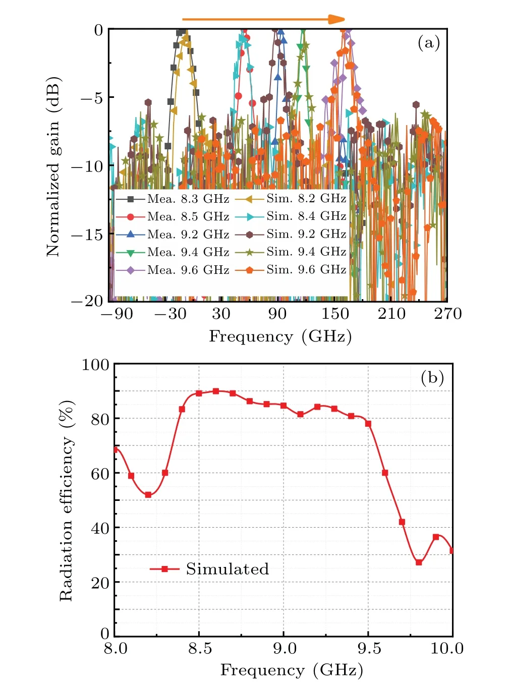
Fig. 8. Measured results of radiation patterns and simulated total efficiency.(a)Simulated and measured normalized E-plane radiation patterns at different frequencies. (b)Simulated total efficiency of the proposed LWA.
4. Experimental validation
The proposed LWA was fabricated using standard printed circuit board (PCB) technology, and verified experimentally in an anechoic chamber. In Fig. 7, the vector network analyzer is used to measure the reflection coefficient,and the radiation mode is measured by the automatic turntable;the results show that the antenna can achieve reflection coefficients below-10 dB in the range of 8.3–9.8 GHz.The experimental results agree well with the simulated results. The frequency offset at the resonant frequency points may be caused by fabrication errors and different relative permittivity of the substrate,but the general trend remains consistent. Figure 7(b)also plots the relationship between realized gain and frequency, showing that the simulated peak gain of 11.6 dBi can be achieved at 9 GHz.

Fig.7. Photograph of the fabricated antenna and performance parameters of the proposed antenna. (a)Photograph of the fabricated antenna under test. (b)Measured and simulated|S11|and gain.

Fig.9. Phase distribution of the proposed SSPP LWA and 3D far-field radiation at corresponding frequency points.
Furthermore,the measured radiation beam can scan from-13°to 162°within the frequency band of 8.2–9.8 GHz,while the simulated radiation beam can scan from-11°to 164°within the frequency band of 8.3–9.6 GHz, as shown in Fig. 8(a). In the experiment, frequency points corresponding to the five directions of backward endfire, backward, broadside, forward and forward maximum radiation angle are extracted and compared. The experimental and simulation results in the same direction can also be accepted for the processing and experimental operation methods, and the overall curves are in good agreement. The frequency scanning characteristics of the antenna radiation beam can be clearly seen from the figure.
As shown in Fig.8(b),the simulated average efficiency of the antenna is as high as 81.4%within the working bandwidth,and the total radiation efficiency drops significantly in relation to the back and endfire directions.
Figure 9 shows the phase distribution of the proposed SSPP LWA, and 3D far-field radiation at corresponding frequency points. The antenna uses single-beam radiation in the operating frequency band, and exhibits outstanding radiating performance in both forward and backward directions.
Our antenna can achieve a large angle at a very high SR,with high radiation efficiency and high gain characteristics,demonstrating superior performance to other types of LWAs in almost all areas,as shown in Table 1.
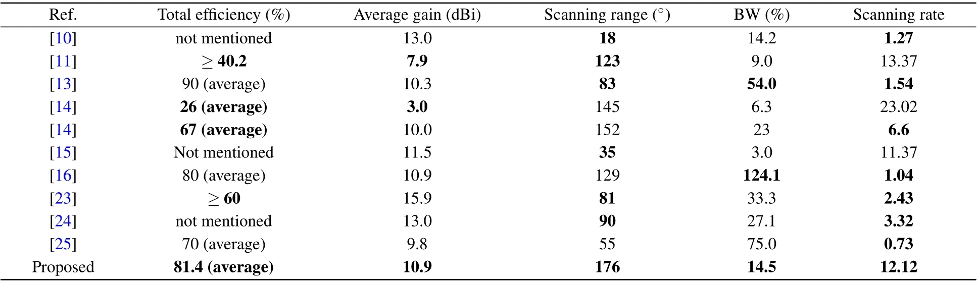
Table 1. Comparison of various antennas of the same type.
5. Conclusion
In this paper, we have proposed a single-beam leakywave antenna with wide-scanning-angle and high-scanningrate based on an SSPP TL. A series of patches is periodically placed near the SSPP TL to couple the EM energy and radiate to free space. The experimental results are in agreement with the simulation and the proposed antenna can realize a high scanning rate of 12.12 while achieving a wide scanning angle from-12°to 164°. The fitted dispersion curve is conducive to calculate the condition of single beam radiation.The formula obtained by fitting discrete points provides effective guidance in terms of antenna design. Our leaky-wave antenna exhibits superior performance to all those demonstrated in similar works. With its high radiation efficiency,wide scanning angle range,and high scanning rate,the proposed shows great potential for application in radar and wireless communication systems.
Acknowledgements
Project supported by the National Natural Science Foundation of China (Grant Nos. 62171460 and 61801508), the Natural Science Basic Research Program of Shaanxi Province,China (Grant Nos. 2020JM-350, 20200108, 20210110, and 2020022), the Postdoctoral Innovative Talents Support Program of China(Grant Nos.BX20180375,2019M653960,and 2021T140111).
猜你喜欢
做人与处世(2021年5期)2021-06-01
好日子(2019年12期)2019-02-14
名作欣赏(2017年25期)2017-11-06
中国新闻周刊(2017年16期)2017-06-15
新天地(2016年11期)2016-12-23
男生女生(银版)(2016年4期)2016-08-04
投资与理财(2016年3期)2016-03-02
椰城(2015年12期)2015-11-18
中学生数理化·中考版(2015年12期)2015-09-10
故事林(2015年1期)2015-05-14

- Chinese Physics B的其它文章
- Formation of high-density cold molecules via electromagnetic trap
- Dynamics of molecular alignment steered by a few-cycle terahertz laser pulse
- Terahertz spectroscopy and lattice vibrational analysis of pararealgar and orpiment
- Molecule opacity study on low-lying states of CS
- Finite-time Mittag–Leffler synchronization of fractional-order complex-valued memristive neural networks with time delay
- Ultrafast Coulomb explosion imaging of molecules and molecular clusters