NiMoO4纳米线@ZnCo MOF(350)核壳结构复合材料的制备及其析氧电催化性能
2022-12-06 06:29魏学东乔双燕
无机化学学报 2022年11期
魏学东 刘 楠 乔双燕
(山西师范大学化学与材料科学学院,太原 030031)
0 Introduction
As resource and environmental issues become more and more prominent,sustainable clean energy has gradually become an alternative solution,among which hydrogen energy has attracted more and more attention due to its high efficiency,cleanliness,and recyclability[1-3].And water electrolysis is considered to be one of the most promising ways to produce hydrogen energy.However,due to the sluggish kinetics of the oxygen evolution reaction(OER),the reaction rate of water electrolysis is limited[4],therefore,it is necessary to design effective electrocatalysts to reduce the OER overpotential.So far,the most efficient electrocatalysts for OER are still noble metal catalysts such as RuO2and IrO2,but their high price and extremely scarce resources hinder their wide commercial application[5-6].Therefore,there is an urgent need to develop inexpensive and abundant non-noble metal OER electrocatalysts.MOFs have attracted extensive attention due to their rich structural diversity and large specific surface area[7-8].MOFs are gradually emerging as reliable templates or precursors for the preparation of metal-active nanomaterials and porous carbons and their composites[9].Researchers have done a lot of work on OER electrocatalysts using MOFs as direct templates or precursors to composite low-dimensional inorganic nanomaterials[10-13].For example,Mu and colleagues[14]reported a Mo-N/C@MoS2multifunctional electrocatalyst synthesized by vertically growing MoS2nanosheets encapsulated in a ZIF structure and then carbonized at high temperature.The hybrid structure exhibited excellent electrocatalytic activity and stability for hydrogen evolution reaction(HER),OER and oxygen reduction reaction(ORR).By direct annealing of reduced graphene oxide(rGO)-coated core-shell bimetallic zeolite imidazole framework,Chen et al.[15]developed a new material (Co@N-CNTs@rGO) with ultrafine Co nanoparticles coated on nitrogen-doped carbon nanotubes(N-CNTs).As-prepared Co@N-CNTs@rGO composite exhibited good HER electrocatalytic activity due to the uniform distribution of Co nanoparticles as well as the large specific surface area and abundant porosity.In electrolytes of 1 mol·L-1KOH and 0.5 mol·L-1H2SO4,the composite exhibited the overpotentials of only 108 and 87 mV at a current density of 10 mA·cm-2,respectively,outperforming most other reported Co-based electrocatalysts.Wang et al.[16]reported a novel N-doped carbon CoP particle/carbon nanotube composite(CNT-NC-CoP),which was developed by in situ nucleation and growth of ZIF67 nanoparticles on carbon nanotubes,which are then carbonized and phosphatized.The unique hierarchical structure endows the CNT-NC-CoP composite with a high specific surface area and abundant active sites.The ultra-low overpotential of 251 mV can be achieved at a current density of 10 mA·cm-2.Wan et al.[17]reported one-dimensional and two-dimensional porous Mo2C nanostructured electrocatalysts.Synthesized by coating one-dimensional MoO3nanowires and two-dimensional MoO3nanosheets with ZIF67 followed by high-temperature carbonization,the obtained Mo2C nanostructures exhibited low onset overpotentials of 25 and 36 mV in 0.1 mol·L-1HClO4and 0.1 mol·L-1KOH solutions,respectively,and small Tafel slopes of 40 and 47 mV·dec-1,respectively.The catalysts also showed excellent stability.
Based on the above reports,we first synthesized NiMoO4nanowires(NWs)by a hydrothermal method,and then in situ grew a layer of ZnCo MOF nanocrystals on the NiMoO4NWs by room temperature liquid phase synthesis to form a coaxial core-shell structure.Then after a low-temperature heat treatment at 350℃(the sample was named NiMoO4NWs@ZnCo MOF(350)),it was found that except for a very small amount of Co3O4quantum dots new phase was inside the ZnCo MOF,the structure and morphology of the composite did not change significantly.The pyrolysis at lower temperatures promotes the generation of new phases,but also basically preserves the original framework structure of MOF,forming a new MOF core-shell structure with more abundant interfaces.The composite electrocatalyst was tested on an inert glassy carbon electrode in 1 mol·L-1KOH,and NiMoO4NWs@ZnCo MOF(350)had an overpotential of only 360 mV at a current density of 10 mA·cm-2and maintained good stability for 30 000 s.
1 Experimental
1.1 Material synthesis
1.1.1 Preparation of NiMoO4NWs
The preparation method of NiMoO4NWs was mainly referred to in the literature[18].1 mmol Ni(NO3)2·6H2O and 1 mmol sodium molybdate were dissolved in 25 mL of deionized water,and after it was completely dissolved,the solution was transferred to a 50 mL reactor,kept at 150℃for 6 h,and the product was collected by centrifugation,washed three times with C2H5OH and dried the precipitate in vacuum at 40℃.
1.1.2 Preparation of NiMoO4NWs@ZnCo MOF composites
10 mg NiMoO4NWs was dissolved in 20 mL methanol,sonicated at 100 kHz for 30 min,and then 38 mg Zn(NO3)2·6H2O and 112 mg Co(NO3)2·6H2O were dissolved in the above solution to form solution A,followed by 40 mg polyvinylpyrrolidone(PVP)and 300 mg of dimethylimidazole were dissolved in 10 mL of methanol to form solution B.Solution B was poured into the solution A,left standing at room temperature for 2 h,the product was collected by centrifugation and washed three times with methanol to precipitate.NiMoO4NWs@ZnCo MOF composites were obtained.
1.1.3 Preparation of NiMoO4NWs@ZnCo MOF(350)
NiMoO4NWs@ZnCo MOF was placed in a porcelain boat,and high-purity argon gas was first passed through the quartz tube for 1 h at room temperature to remove the residual air in the quartz tube,and then kept at 350℃for 3 h.NiMoO4NWs@ZnCo MOF(350)was prepared well.
1.2 Structural characterization
Structural characterizations were carried out on various large-scale analytical instruments.Among them,X-ray diffraction analysis(XRD)was performed on a Philips 1830 diffractometer equipped with a Cu Kα radiation source,a 2θ range of 5°-90°,a working voltage of 40 kV,a working current of 40 mA,and a speed of 20(°)·min-1.Using field emission scanning electron microscopy(FE-SEM,SU-8010)to analyze the surface topography of the samples at the operating voltage of 5.0 kV.Nanoscale microscopic topography could be analyzed on transmission electron microscopy(TEM,JEM-2100F)and high-resolution transmission electron microscopy(HRTEM)at an accelerating voltage of 200 kV.X-ray photoelectron spectroscopy (XPS)was obtained using a K-Alpha spectrometer equipped with an Al Kα X-ray source to analyze the surface chemical states and electronic states of various elements.
1.3 Electrochemical performance test
All electrochemical performance tests of the material samples were carried out with a three-electrode system(the material electrode was the working electrode,the platinum foil was the counter electrode,and the Ag/AgCl was the reference electrode).The test instrument used Shanghai Chenhua Electrochemical Workstation CHI660E.It mainly includes linear sweep voltammetry(LSV),Tafel slope,cyclic voltammetry,electric double layer capacitance(Cdl),chronoamperometry,etc.Among them,the scanning speed of OER catalytic performance tested by LSV was 10 mV·s-1,and the voltage range was 1-2 V(vs RHE);The current density of 10 mA·cm-2was used for stability test by chronopotentiometry,and the time was set to 12 h.
2 Results and discussion
2.1 Structure and morphology characterization
Fig.1 is a schematic diagram of the synthesis process for NiMoO4NWs@ZnCo MOF(350)electrocatalyst.First,NiMoO4NWs were synthesized under hydrothermal conditions,and then 10 mg of the synthesized NiMoO4NWs were dissolved in a methanol solution of cobalt nitrate and zinc nitrate,and methanol solution dissolved with PVP and dimethylimidazole was added to it.The mixed solution was left at room temperature for 2 h,and the NiMoO4NWs@ZnCo MOF material was obtained by centrifugal washing,and the material was calcined at 350℃for 3 h in a high-purity argon flow to obtain the final NiMoO4NWs@ZnCo MOF(350)electrocatalyst.
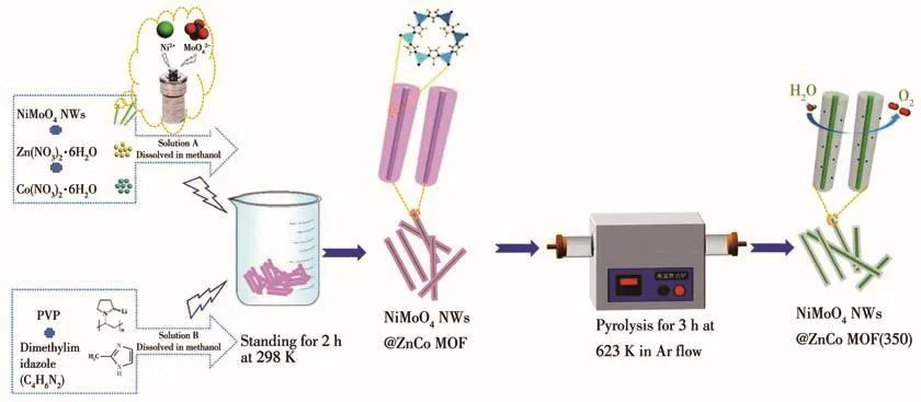
Fig.1 Schematic diagram of the preparation process of NiMoO4NWs@ZnCo MOF(350)
As shown in Fig.2a,as-synthesized NiMoO4NWs@ZnCo MOF was tested on an electrochemical workstation and found that the overpotentials were 420 and 540 mV at current densities of 10 and 50 mA·cm-2,respectively.Which is superior to the electrocatalytic performance of NiMoO4NWs and ZnCo MOF monomer samples.Therefore,it is judged that the twophase interface enhances the electrocatalytic activity,and although the electrocatalytic activity of NiMoO4NWs@ZnCo MOF is not high,it is still a potential MOF composite.To further improve its electrical conductivity and electrochemical performance,NiMoO4NWs@ZnCo MOF was subjected to pyrolysis experiments at 350,450,550,and 650℃,respectively.And it was found that the samples had the smallest overpotential at 350℃ (349 mV at 10 mA·cm-2,470 mV at 50 mA·cm-2)in Fig.2b.So NiMoO4NWs@ZnCo MOF(350)was selected as the research object to systematically study the structure and electrochemical performance.
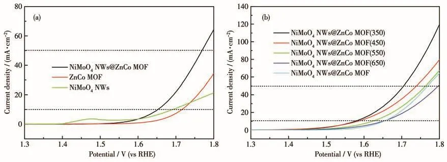
Fig.2 (a)LSV plots of NiMoO4NWs,ZnCo MOF,and NiMoO4NWs@ZnCo MOF;(b)LSV plots of the pyrolyzed NiMoO4NWs@ZnCo MOF at different temperatures
Fig.3a shows the XRD patterns of as-synthesized NiMoO4,which is basically consistent with the NiMoO4·xH2O standard diffraction card(PDF No.13-0128).The XRD pattern showed that an inconsistent small peak at 13.56°existed in real synthetic samples[18-19].So it demonstrated the successful synthesis of NiMoO4NWs.It can be seen from Fig.3a that for the pure ZnCo MOF,the diffraction peaks are consistent with the diffraction peak positions and intensities of the ZnCo MOF crystals reported in the literature[20-21],and no impurity peaks were observed,indicating that the synthesized ZnCo MOF sample has higher crystallinity.For NiMoO4NWs@ZnCo MOF,except for the most diffraction peaks of ZnCo MOF,only a weaker peak of NiMoO4NWs appeared in the composite.The NiMoO4NWs monomer itself has strong crystallinity,which indicates the experimental fact that NiMoO4NWs were tightly coated by ZnCo MOF to form a coreshell structure.All the above results indicate the successful synthesis of the NiMoO4NWs@ZnCo MOF precursor.As shown in Fig.3b,NiMoO4NWs,ZnCo MOF,and NiMoO4NWs@ZnCo MOF were pyrolyzed at 350℃,and it was found that compared with the precursor,the characteristic peaks of the monomers like NiMoO4NWs(350)and ZnCo MOF(350)can be well maintained,indicating that the thermal stability of the monomer sample is good,especially for the ZnCo MOF(350)which does not show a lot of coordination bond breakage and framework collapse.The intensity of its diffraction peaks decreased significantly compared with that before calcination.At 350℃,NiMoO4NWs@ZnCo MOF(350)obviously underwent a little pyrolysis,a small amount of new Co3O4phase(PDF No.43-1003)appeared in the composite,and the peaks of the NiMoO4NWs phase appeared at several positions and the intensity increased,indicating that a little pyrolysis caused the ZnCo MOF shell to become loose and porous,and the diffraction peaks of the NiMoO4NWs core appeared stronger.However,the composite sample still kept the framework structure of MOF unchanged,although the intensity of its diffraction peaks was greatly reduced.However,when the pyrolysis temperature was increased to 450℃according to XRD patterns in Fig.S1(Supporting information),the composite structure was basically destroyed,and it mainly evolved into another composite structure of a new NiMoO4(PDF No.45-0142)and CoO(PDF No.43-1004).In addition,the structure of pyrolyzed samples at 450,550,and 650℃was consistent and different from the pyrolyzed sample at 350℃,so the special structure of NiMoO4NWs@ZnCo MOF(350)determined its excellent catalytic activity.
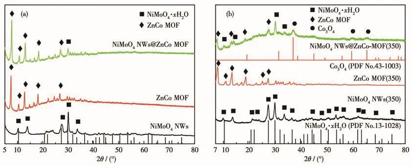
Fig.3 (a)XRD patterns of NiMoO4NWs,ZnCo MOF,and NiMoO4NWs@ZnCo MOF;(b)XRD patterns of NiMoO4NWs(350),ZnCo MOF(350),and NiMoO4NWs@ZnCo MOF(350)
The microscopic morphology is shown in Fig.4.It can be observed from Fig.4a that the morphology of NiMoO4NWs was uniform one-dimensional NWs,and the diameter of the NWs was about 50 nm.Then,after adding the methanol solution of 2-methylimidazole and PVP to the methanol suspension of NiMoO4NWs,Zn(NO3)2·6H2O and Co(NO3)2·6H2O,ZnCo MOF nanocrystals were found to grow rapidly and attach to NiMoO4NWs.On the surface of NiMoO4NWs,a composite electrocatalyst with ZnCo MOF wrapped around NiMoO4NWs was obtained.
The SEM image of the composite electrocatalyst is shown in Fig.4c.It can be clearly observed that for the NiMoO4NWs@ZnCo MOF composite electrocatalyst,the growth of ZnCo MOF was strictly restricted to the surface of NiMoO4NWs,and a coating layer with relatively uniform thickness was formed.The SEM image in Fig.4b is the ZnCo MOF nanocrystals synthesized separately.ZnCo MOF exhibited a good dodecahedral crystal form,with uniform morphology,sharp edges and corners,and a smooth surface,and the particle size was about 400 nm.From the SEM image of NiMoO4NWs@ZnCo MOF(350)in Fig.4d,the morphology of the pristine ZnCo MOF was largely preserved,indicating that the MOF framework is not completely collapsed.The morphology change of the pyrolytic sample at 650℃was also studied in Fig.S2,and it was found that the structure collapse was aggravated,and the pyrolysis products of some ZnCo MOF precursors were aggregated.
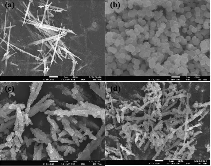
Fig.4 SEM images of(a)NiMoO4NWs,(b)ZnCo MOF,(c)NiMoO4NWs@ZnCo MOF,and(d)NiMoO4NWs@ZnCo MOF(350)
To deeply explore the size,structure,and morphology of the synthesized electrocatalysts,TEM and HRTEM tests were carried out(Fig.5).Fig.5c is the TEM image of NiMoO4NWs@ZnCo MOF(350).Compared with NiMoO4NWs@ZnCo MOF in Fig.5a,the composite sample after pyrolysis well-maintained precursor morphologies of one-dimensional NWs before calcination.And the ZnCo MOF crystal shell appeared as uniformly dispersed nanoparticles without obvious agglomeration,which is because a little pyrolysis occurs during the calcination at 350℃,and the pore structure of MOF as a template and the gas generated after thermal decomposition also play a good role in inhibiting the crystal polymerization.Fig.5b is the HRTEM image of NiMoO4NWs@ZnCo MOF.It can be seen that the lattice fringes of NiMoO4NWs were clear,marked as the NiMoO4·xH2O phase with a lattice spacing of 0.299 nm,which is closely related to the ZnCo MOF phase.The interface was almost seamless.The high-resolution image of NiMoO4NWs@ZnCo MOF(350)in Fig.5d after pyrolysis showed a similar structure,but a small amount of Co3O4marked with a lattice spacing of 0.244 nm appeared at the local position of the ZnCo MOF pyrolysis phase,apparently,the structure is consistent with the XRD analysis results in Fig.3.The two-phase interface continues to behave as a tight connection,and there should be chemical bonds other than intermolecular forces.Further elemental mapping of NiMoO4NWs@ZnCo MOF(350)in Fig.5e-5l showed that C,N,O,Co,Zn,Ni,and Mo elements co-existed in the sample and exhibited an obvious coreshell structure.And the Zn and Co elements of ZnCo MOF were densely distributed on the longitudinal axis of the NWs and distributed on the shell of the coreshell structure,and the Ni and Mo elements of NiMoO4NWs were obviously distributed on the core of the coreshell structure.
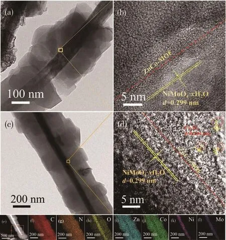
Fig.5 (a)TEM image and(b)HETEM image of NiMoO4NWs@ZnCo MOF;(c)TEM image,(d)HETEM image,(e)STEM image,and(f-l)elemental mappings of NiMoO4NWs@ZnCo MOF(350)
In order to further characterize the valence states of elements in NiMoO4NWs@ZnCo MOF and NiMoO4NWs@ZnCo MOF(350)composites,the XPS spectra were detected and the peaks were fitted.As shown in Fig.6a,the characteristic peaks of Ni2p3/2and Ni2p1/2for NiMoO4NWs@ZnCo MOF were 855.5 and 873.1 eV,respectively,which can be assigned to Ni2+.For NiMoO4NWs@ZnCoMOF(350),the characteristic peak of Ni2+remained unchanged but shifted by 0.5 eV[22].As shown in Fig.6b,for NiMoO4NWs@ZnCo MOF,the Mo3d5/2peak and the Mo3d3/2characteristic peak of the Mo3d XPS spectrum were located at 232.2 and 235.3 eV,respectively,indicating the existence of Mo6+[23].For the pyrolyzed NiMoO4NWs@ZnCo MOF(350),the valence state of Mo6+was unchanged and shifted by 0.5 eV.In the XPS spectrum of Zn2p,the peaks at 1 021.2 and 1 044.3 eV were characteristic peaks of Zn2p3/2and Zn2p1/2,respectively(Fig.6c)[24],corresponding to the Zn2+in NiMoO4NWs@ZnCo MOF.While for NiMoO4NWs@ZnCo MOF(350),the characteristic peak of Zn2+was unchanged but shifted negatively by 0.5 eV.The positive or negative shifts of the characteristic peaks of the above metal ions indicate that the two-phase interface of NiMoO4NWs and ZnCo MOF has stronger electronic interactions after pyrolysis[25-26].
In the Co2p spectrum of NiMoO4NWs@ZnCo MOF,the binding energies at 780.9 and 796.3 eV belong to Co2p2/3and Co2p1/2,respectively,indicating that the cobalt element exists in the form of Co2+[27](Fig.6d).For NiMoO4NWs@ZnCo MOF(350)after pyrolysis,the main valence peak remained Co2+,but shifted negatively by 0.7 eV compared with that before pyrolysis,indicating that the electronic interaction at the interface is more intense for the phase after pyrolysis.Co2p3/2and Co2p1/2corresponded to the characteristic peaks of Co3+at 780.2 and 795.4 eV,respectively,indicating that Co2+and Co3+coexist in NiMoO4NWs@ZnCo MOF(350).It marks the appearance of a new phase of Co3O4[28],which is consistent with the analysis results in Fig.3b and 5d.The results show that various metal ions coexist in the composite,and their presence accelerates the electron transport speed and enhances its catalytic activity.
The binding energy peaks of C1s in NiMoO4NWs@ZnCo MOF are shown in Fig.6e.With the appearance of the high-temperature pyrolysis Co3O4phase,four binding energy peaks appeared at 284.5,285.1,286.2 and 288.5 eV,which can correspond to C—C(sp2),C—N,C—O—Mo,andC=O bonds,respectively[29-31].It shows that a small amount of C=O bonds were produced by pyrolysis.In addition,as shown in Fig.6f,530.3,531.2,531.8,and 532.7 eV appeared in O1s of NiMoO4NWs@ZnCo MOF,corresponding to Mo—O bond(or Ni—O bond),oxygen vacancies(oxygen defects),C—O—Mo bond,and hydroxide(or adsorbed oxygen or moisture)[32-33].For NiMoO4NWs@ZnCo MOF(350),the peaks of O1s can be separated into five peaks at 529.4,530.3,531.2,531.8,and 532.7 eV.Except for the four peaks,before pyrolysis was retained,the binding energy peak at 529.4 eV corresponds to the spinel-type cobalt oxide(i.e.,the Co3O4phase).Through the above analysis of the XPS spectra,for NiMoO4NWs@ZnCo MOF and NiMoO4NWs@ZnCo MOF(350),chemical bonds C—O—Mo and a large number of oxygen vacancies were generated at the monomer phase heterointerface,which can become the source of active sites and increase the electrocatalytic activity of the composites,especially NiMoO4NWs@ZnCo MOF(350),in addition to retaining the interfacial chemical bonds and oxygen vacancies before pyrolysis,partial pyrolysis also leads to the formation of Co3O4phase,which also leads to the formation of a new phase interface and further increases the active sites of the heterointerface.

Fig.6 XPS spectra of(a)Ni2p,(b)Mo2d,(c)Zn2p,(d)Co2p,(e)C1s,and(f)O1s in NiMoO4NWs@ZnCo MOF and NiMoO4NWs@ZnCo MOF NWs(350)
2.2 Electrochemical performance
The OER performance was performed in 1 mol·L-1KOH solution using a conventional three-electrode system.The LSV curves are shown in Fig.7a,when the current density reached 10 mA·cm-2,the overpotential of NiMoO4NWs@ZnCo MOF(350)was only 360 mV,which was lower than 700 mV of the single-component NiMoO4NWs(350)and 430 mV of ZnCo MOF(350).Tafel slope is an essential parameter for describing the kinetic reaction mechanism of catalysts,which is calculated according to the Tafel equation:η=blg j+a(η is the overpotential,j represents the current density and b belongs to the Tafel slope).To further investigate the OER kinetic properties of the samples,Fig.7b shows the Tafel slopes of the three samples.The Tafel slope of NiMoO4NWs@ZnCo MOF(350)was 62 mV·dec-1,which was much smaller than 294 mV·dec-1of NiMoO4NWs(350)and 98 mV·dec-1of ZnCo MOF(350).It reveals that NiMoO4NWs@ZnCo MOF(350)has a faster electrocatalytic reaction rate of oxygen evolution.Fig.7c is the stability curves of NiMoO4NWs@ZnCo MOF(350)and the single components.It can be observed that the current density of the composite sample NiMoO4NWs@ZnCo MOF(350)was the highest close to 10 mA·cm-2under the same overpotential,and can be maintained for 30 000 s with basically no decay.The stability curve for a longer time was further studied,and it was found that after 50 000 s,the initial current density of the composite sample was attenuated,but still retained at 67%,as shown in Fig.S3.Then,the electrochemical impedance spectroscopy(EIS)of the electrocatalyst was tested.The smaller semicircular arc diameter represents a smaller charge transfer resistance(Rct)and therefore a faster OER.NiMoO4NWs@ZnCo MOF(350)in Fig.7d had a smaller impedance radius and a charge transfer resistance of about 73.4 Ω,which was lower than that of NiMoO4NWs(350)(239.4 Ω)and ZnCo MOF(350)(86.37 Ω).

Fig.7 (a)LSV plots,(b)Tafel slope plots,(c)stability plots,and(d)impedance plots of NiMoO4NWs(350),ZnCo MOF(350),and NiMoO4NWs@ZnCo MOF(350)
The Cdlof the electrocatalyst which can be used to compare the size of the electrochemical specific surface area was calculated by CV test.The electrochemical-specific surface area is proportional to the Cdl.The larger the electrochemical specific surface area of the catalyst,the larger the Cdl,which means the more catalytic active sites and the better catalytic performance of the catalyst.As shown in Fig.8a-8c,NiMoO4NWs(350),ZnCo MOF(350),and NiMoO4NWs@ZnCo MOF(350)were tested at different scanning speeds of 10-100 mV·s-1.The obtained CV curves were then linearly fitted to obtain the Cdl.As shown in Fig.8d,the Cdlof NiMoO4NWs@ZnCo MOF(350),NiMoO4NWs(350),and ZnCo MOF(350)were 9.535,0.162,and 4.195 mF·cm-2,respectively.The results once again proved that NiMoO4NWs@ZnCo MOF(350)had a higher specific surface area for electrochemical activity.
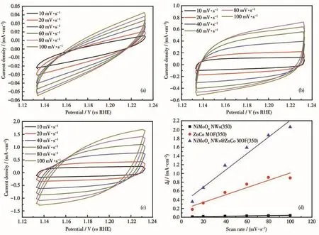
Fig.8 CV curves of(a)NiMoO4NWs(350),(b)ZnCo MOF(350),and(c)NiMoO4NWs@ZnCo MOF(350)in a non-Faradaic range;(d)Plots of the current density difference(Δj,Δj=ja-jc,where jaand jcrepresent the positive and negative current densities,respectively)against scan rate(the slope is twice that of Cdlin the Fig.8d)
At present,the accepted OER mechanism[34]for alkaline conditions can be expressed as:

In the above reaction formula,*represents the active site of the catalyst,and O*,HO*,and HOO*represent three different oxygen-containing intermediates.According to the reaction mechanism,and all the above structural and electrochemical analysis results,several active sites or site sources such as C—O—Mo bond,oxygen vacancies,new Co3O4phase,all of the heterophase interfaces,and new increase specific surface of NiMoO4NWs@ZnCo MOF(350)are more likely to adsorb more hydroxyl oxygen atoms and achieve faster conversion of oxygen molecules.
To further study the changes in the morphology and electrocatalytic performance of the sample after the stability test,Fig.9a shows the SEM image of NiMoO4NWs@ZnCo MOF(350)after the stability test.Compared with Fig.4d,the morphology of the composite sample before and after the stability test did not change significantly,showing good physical stability characteristics.In Fig.9b,the changes of the LSV curves before and after the stability test were observed,and it was found that the overpotential at 10 mA·cm-2hardly increased,while the overpotential at 50 mA·cm-2increased by less than 20 mV,indicating that the stability test did not significantly alter the electrocatalytic activity of NiMoO4NWs@ZnCo MOF(350).
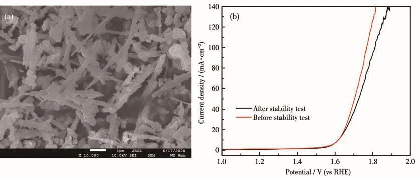
Fig.9 (a)SEM image after stability test and(b)LSV curves before and after stability test for NiMoO4NWs@ZnCo MOF(350)
3 Conclusions
In this experiment,a new type of ZnCo MOF nanoparticles was successfully synthesized by in situ growth synthesis on NiMoO4NWs and then carbonized.The pyrolysis temperature of 350℃maintained the morphology of the precursor well,and a small amount of the Co3O4phase appeared.The appearance of the Co3O4phase made the surface of the material more rough,loose,and porous,which is beneficial to increase the effective contact area between the catalyst and the electrolyte.Moreover,the unique core-shell structure endows the material with a high specific surface area,abundant exposed active sites,fast ion diffusion paths,and good electrical conductivity.Therefore,the electrocatalyst exhibited a low overpotential of 360 mV at a current density of 10 mA·cm-2and maintained longterm durability of 30 000 s.
Supporting information is available at http://www.wjhxxb.cn
Acknowledgment:This study was supported by the General Project of Basic Research Program of Shanxi Province(Grant No.20210302123332),the National Natural Science Foundation of China(Grant No.22178204),and the 1331 Engineering of Shanxi Province.
猜你喜欢
食品科学(2022年20期)2022-10-31
材料研究与应用(2022年3期)2022-07-04
西南科技大学学报(2021年4期)2022-01-15
发光学报(2021年7期)2021-07-23
人工晶体学报(2019年7期)2019-08-22
人工晶体学报(2019年3期)2019-04-17
中国有色金属学报(2018年2期)2018-03-26
分析化学(2018年12期)2018-01-22
组织工程与重建外科杂志(2018年6期)2018-01-12
中南大学学报(自然科学版)(2016年2期)2017-01-19