
Optimization Design of Air Conditioning Outdoor Unit Top Plate Based on Orthogonal Test
2023-01-29 07:22WengangLiuShaohuaChenJiaxinHouJunlongXie
风机技术 2022年6期
Wen-gang Liu Shao-hua Chen Jia-xin Hou Jun-long Xie
(School of Energy and Power Engineering,Huazhong University of Science and Technology)
Abstract:In this paper,the modal analysis of an air conditioner outdoor unit is carried out and the simulation results are compared with the experimental results to verify its accuracy.A separate structural optimization analysis is performed for the top plate,and the compression bars of the top plate are changed from transverse to vertical placement.The simulation results show that the natural frequency and stiffness of the top plate are improved.Under the premise of vertical placement of the compression bars,a three-factor,three-level orthogonal test is conducted to find the optimal combination of low-order natural frequency and high-order natural frequency in the given range.
Keywords:Air Conditioner Outdoor Unit;Top Plate;Structure Optimization;Compression Bars;Orthogonal Test
1 Introduction
The structural design of the air conditioner outdoor unit is an important part of the outdoor unit development.It not only determines the weight but also has an impact on the performance of the whole unit[1].In addition to meet the basic requirements of support and easy installation,the design of the unit should have excellent vibration noise performance at a deeper level,which means the unit vibrates less under the action of the same excitation source.
Liu[2] et al.used numerical simulations such as modal analysis and optimization analysis to improve efficiency and guided the development of a new type of air conditioner outdoor unit.The sheet metal rigidity was improved by up to two times or more,and the vibration of the whole unit was less than that of the original unit.Zhu[3] optimized the air guide ring of the front panel of the outdoor unit,and the vibration condition was improved.Chao[4]et al.used a combination of CAE analysis and dynamics test to analyze the excitation source,structural mode and vibration response characteristics of the unit vibration,and proposed an optimized improvementplan,whichachievedabettervibrationreductioneffect.
Orthogonal experiments are more widely used in the field of optimal design of machinery.Wang[5] et al.used orthogonal experimental design and computational fluid dynamics (CFD) methods to obtain centripetal turbine blades with optimal NACA blade top profiles.Zhao[6] et al.parametrically modeled the W-shaped metal seal ring and calculated the results using the numerical simulation orthogonal test method.Zhang[7] et al.used the orthogonal test method to analyze several factors affecting the strength of the centrifugal impeller and obtained the most significant factors.Similarly,Pang[8]et al.used the orthogonal test method to identify the key structural parameters affecting the friction loss of the impeller and compared the significance of their effects.
This paper simulates the top plate of the outdoor unit combined with the finite element analysis.It uses the simulation data to design orthogonal experiments to optimize the structure of the top plate and obtain a more reasonable layout of reinforcement[9].
2 Modal Analysis of Air Conditioner Outdoor Unit Box
Modal analysis is used to determine the vibration characteristics of a designed structure or machine component,i.e.,the natural frequency and mode shapes of the structure,which are important parameters in the design of structures subjected to dynamic loads.It can also be used as a starting point for other dynamics analysis problems,such as transient dynamics analysis,harmonic response analysis and spectral analysis.Modal analysis is also a necessary preliminary analysis for spectral analysis,harmonic response analysis and transient dynamics analysis.The basic equation for the solution of a typical undamped modal analysis is the classical eigenvalue problem:

Where [K] is the stiffness matrix;{ϕi} is the oscillation vector(eigenvector) of theith-order mode,andωiis the natural frequency of theith-order modeis the eigenvalue);[M]is the mass matrix.
The modal analysis of the unit can be used to obtain the natural frequency and the corresponding mode shapes.The natural frequency and mode shapes can be applied to the design of the unit to avoid the excitation frequency of the moving parts such as the compressor and fan,reducing the vibration and noise of the cabinet.From the methodological point of view,modal analysis is divided into computational modal analysis and experimental modal analysis.If the modal parameters are obtained by finite element calculation,it is called computational modal analysis (CAE analysis).If the input and output data are obtained by sensors and data acquisition equipment,and then the modal parameters are obtained by parameter identification,it is called experimental modal analysis.Both have their advantages and disadvantages.From the perspective of result accuracy: the experimental model is measured on the actual structure,so the modal parameters obtained from the analysis are very accurate.While the computational model is a lot of model simplification processing and contact processing done on the actual structure,the uncertainty is larger.From the perspective of result integrity: the experimental mode order is far from the calculated mode because it is affected by the channel,measurement point,excitation force and bandwidth.Therefore,the two analysis methods should be used in combination.In the preexperimental modal stage,the computational modal analysis can help to determine the distribution of measurement points and reference point locations in the experiment.In the later stage,the results of the experimental modal can be used to calibrate the finite element model and improve the accuracy of computational modal analysis[10].

Fig.1 Test model and measurement points
3 Modal Simulation
3.1 Material Setting
The material used in the simulation is structured steel with Poisson's ratio of 0.3,modulus of elasticity of 2×10⁵MPa and density of 7.85×10⁻⁶kg/mm3.
3.2 Boundary Condition Setting
The connection between the outdoor unit parts is mainly by bolt locking,and the face contact between the parts containing the bolt connection is set to bonded contact.The parts in contact with each other have no relative displacement under the action of the bolt and make up the outdoor unit combined into a whole.
3.3 Grid Settings
Since the model is very complex,the meshing method used is automatic and the mesh type is unstructured mesh.The mesh size is set separately for each part because the mesh size and number have a great influence on the final simulation results.
3.4 Modal Test
As shown in Figure 1,the acceleration sensor is arranged on the outdoor unit case,and the force hammer is used to move the knocking in the top plate,side plate and front plate.There are 28 knocking points in the case.
The validity of the modal frequencies was checked by the modal assurance criterion(MAC).Generally,after decoupling the modes of each order,the diagonal matrix is 1,and the non-diagonal any two-order mode correlation ≤35% is judged as a high confidence level.For the correlation >35%of the two-order modal need to be further analyzed.For adjacent modes,it is necessary to judge whether spurious modes exist due to mathematical poles,and for non-adjacent modes,it is necessary to judge whether spatial mixing is caused by too few measurement points and other specific settings.
Through MAC modal verification,some obvious modal frequencies were selected,and the modal frequencies were compared and calibrated with CAE simulation.The results are shown in Figure 2.
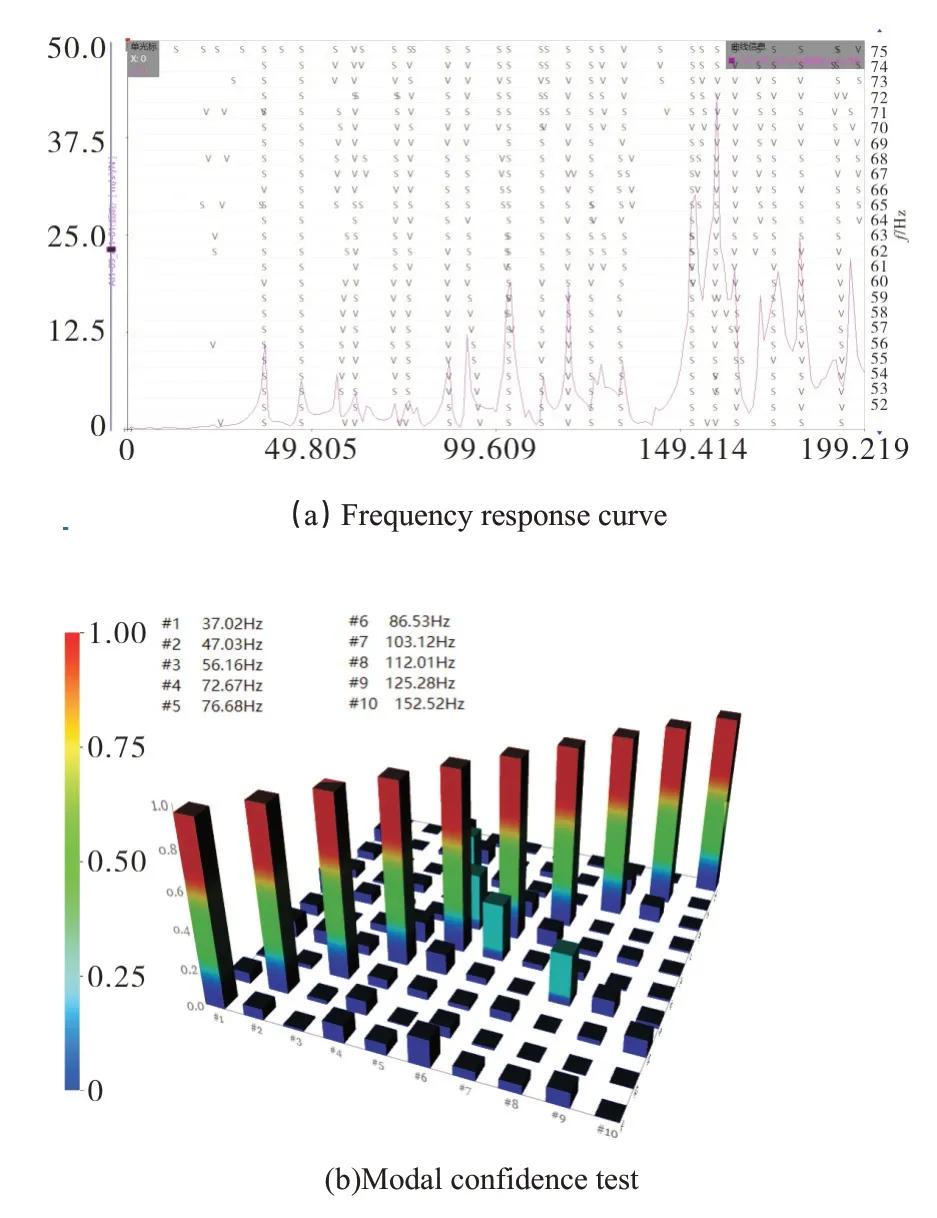
Fig.2 Modal frequencies and confidence test
3.5 Test and Simulation Comparison
As shown in the Table 1,the experimentally measured frequencies and mode shapes of the three components basically match the simulation results.The error is within 5%,which can verify the accuracy of the simulation results and provide a basis for the subsequent CAE analysis of the air conditioner outdoor unit.

Tab.1 Comparison of test and simulation data
As shown in the Figure 3,the top plate is separated from the whole machine model for separate simulation.The same mesh and boundary condition settings are used to obtain the first-order natural frequency of 46Hz,which is similar to the first-order top plate natural frequency in the whole machine simulation.From the Figure 3(b),the first order natural frequency of the top plate is in the center,and the first order inherent frequency of the top plate is 46Hz which is close to the excitation frequency of the compressor 50Hz.
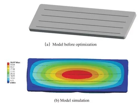
Fig.3 Static simulation of top plate before optimization
4 Structural Optimization Solutions
In order to save the calculation time and improve the calculation efficiency,the optimization verification is only for the top plate simulation calculation.
The width,number,height,support form and shape of the compression bars will have an effect on the stiffness of the top cover plate[12].As shown in the Figure 4,it was found that changing the top plate compression bar direction from horizontal to vertical placement would have a greater increase in the natural frequency of the top plate.The main deformation position changes from the center to the side without bolts.
In addition,the stiffness of the top cover=load/displacement,where the load is fixed at 500 N and the displacement is the maximum displacement from the simulation[11].Static analysis is performed for these two types of compression bars distribution respectively.As shown in the Figure 5,The deformation of the top plate before the optimization is 6.6mm,and the deformation of the top plate after optimization is 3mm.Under the same load,the deformation of the top plate after optimization is smaller and more rigid than that before optimization.This is due to the change in the direction of the compression bars and the reduction in the length of the compression bar to enhance the strength at the center of the top plate,making it less prone to deformation.
With the change of compression bars to vertical placement,a three-factor,three-level orthogonal experiment was conducted to investigate a good solution for the length,width and number of compression bars.

Fig.4 Static simulation of top plate optimization
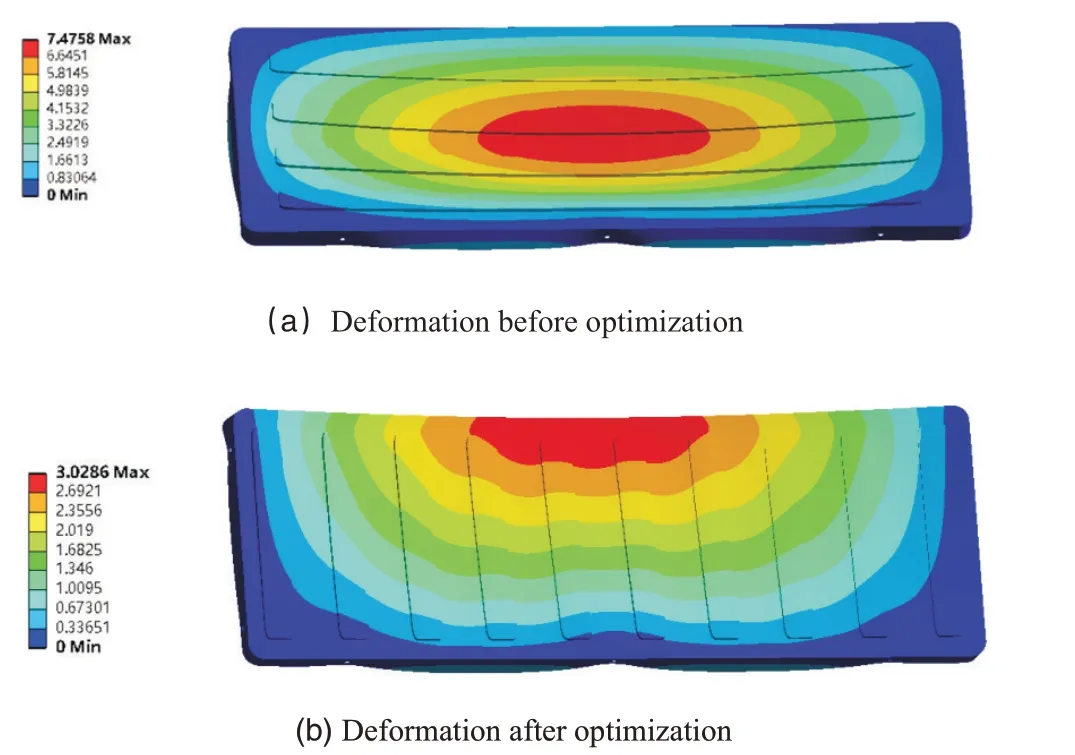
Fig.5 Deformation before and after optimization
Based on the length and width of the top plate,the head design of the orthogonal Table 2 is following.
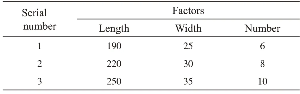
Tab.2 Head design of the orthogonal
5 Numerical Results and Analysis
According to the orthogonal Table 3,the simulation is performed for nine groups of design solutions,and the natural frequencies of each group can be obtained.The following table shows the extreme difference analysis for the low-order natural frequencies.
In the Table 3,jis the serial number of the influencing factor,andⅠj,Ⅱj,Ⅲjare the sum of the corresponding level indicators under the three factors.Rjis the polar difference of the sum of the frequencies in columnj.In the orthogonal experiment,the range is used to evaluate the influence of the factors on the indexes in the experiment.Factors with small range have less influence on the indicators and can be regarded as unimportant factors.Factors with large range have a greater influence on the experimental results and are treated as important factors.
It can be seen from the Table 3 that the length of compression barsR1>the number of compression barsR3>the width of compression barsR2.It can be concluded that the length of compression bars is the main factor affecting the low-order natural frequency of the top plate,and the number and width of compression bars are secondary factors.
The combination with the best frequency can be selected as the better optimization scheme from the 9 sets of experiments.However,there are other level combinations that have not been experimented (there are 27 level combinations,and only 9 of them have been selected for the orthogonal experiment),and the best conditions in the full-scale experiment can be found by a simple calculation.The greater the frequency in this design scheme,the better.ⅡA=203.9>ⅠA=200>ⅢA=190.4,so factorAchooses levelA2.Similarly,factorsBandCchoose levelB2C3.For the top plate low order natural frequency of the best design scheme is the length of 220mm,the width of 30mm,and the number of 10 bars.
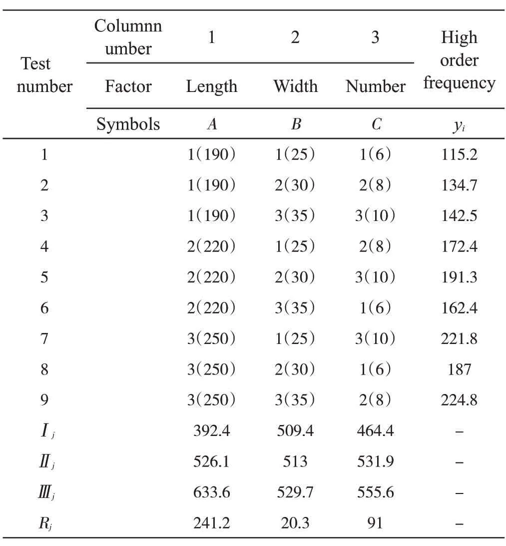
The following table shows the range analysis for the high-order natural frequencies.
It can be seen from the Table 4 that the length of compression barsR1>the number of compression barsR3>the width of compression barsR2.It can be obtained that the length of compression bars is the main factor affecting the high-order frequency of the top plate,and the number and width of compression bars are secondary factors.The same method of calculating the lower-order natural frequency is used to find the best combination in a comprehensive experiment.The best design solution for the top plate with higherorder natural frequency is the length of 250 mm,the width of 35 mm,and the number of 10 bars.This horizontal combination is not simulated in the orthogonal experiment.
As shown in the Figure 6,the simulation result of the higher-order natural frequency of this combination is 232Hz,which is larger than the frequencies of all combinations in the orthogonal experiment.The correctness of the experiment is verified.
Analyzing and comparing the data results of the two tables,the length,width and number of top plate compression bars have the same order of influence on the low-order and high-order natural frequencies but not the same level and law of influence.The three factors have little effect on the low-order natural frequency but significantly affect the higher-order natural frequency.There is an optimal range for the length and width of the compression bars for the lower-order natural frequency.For the high-order natural frequency,the greater the length and width of the compression bars,the better.

Tab.3 Low-order natural frequencies orthogonal test
Tab.4 High-order natural frequencies orthogonal test

Fig.6 Comparison of deformation of top plate before and after optimization
6 Conclusion
In this paper,the modal analysis of an air conditioning outdoor unit is carried out to obtain the inherent frequency and vibration pattern of the outdoor unit top plate.The simulation results are compared with the experimental results to verify their accuracy.The top plate is optimized by changing the position of the compression bars from transverse orientation to vertical orientation,which will effectively improve the order frequencies of the top plate.A three-factor,three level orthogonal experimental design was designed for the length,width and number of compression bars.The final results show that a length of 220 mm,a width of 30 mm,and a number of 10 bars would have a higher low-order natural frequency,and a length of 250 mm,a width of 35 mm,and a number of 10 bars would have a higher high-order natural frequency.

- 风机技术的其它文章
- 机匣处理在无喷嘴径流涡轮叶片抑振中的应用*
- Study on Loss Quantitative Analysis Methodology for Highly-loaded Transonic Fan*
- Influence of Change Law of Blade Leading-Edge Ellipse Ratio on Inception Cavitation Performance of Centrifugal Pump*
- 带诱导轮的离心式航空燃油泵空化特性分析*
- 重燃透平叶片真实内部冷却通道的传热特性研究*
- Numerical Study of Film/Shock Interaction on Suction Surface of Transonic Turbine Cascade*