
Isogeometric Analysis of Longitudinal Displacement of a Simplified Tunnel Model Based on Elastic Foundation Beam
2023-02-17 03:13ZhihuiXiongLeiKouJinjieZhaoHaoCuiandBoWang
Zhihui Xiong,Lei Kou,Jinjie Zhao,Hao Cui and Bo Wang
School of Water Conservancy Science and Engineering,Zhengzhou University,Zhengzhou,450001,China
ABSTRACT Serious uneven settlement of the tunnel may directly cause safety problems.At this stage,the deformation of the tunnel is predicted and analyzed mainly by numerical simulation,while the commonly used finite element method(FEM)uses low-order continuous elements.Therefore,the accuracy of tunnel settlement prediction is not enough.In this paper, a method is proposed to study the vertical deformation of the tunnel by using the combination of isogeometric analysis(IGA)and Bézier extraction operator.Compared with the traditional IGA method,this method can be easily integrated into the existing FEM framework, and ensure the same accuracy. A numerical example of an elastic foundation beam subjected to uniformly distributed load and an engineering example of an equivalent elastic foundation beam of the tunnel are given.The results show that the solution of the IGA method is closer to the theoretical solution of the initial-parameter method than the FEM,and the accuracy and reliability of the proposed model are verified.Moreover,it not only provides some theoretical support for the longitudinal design of the tunnel,but also provides a new way for the application and popularization of IGA in tunnel engineering.
KEYWORDS Isogeometric analysis;Bézier element;Winkler foundation beam;tunnel
1 Introduction
Elastic foundation beams are widely utilized in the foundation of industrial,civic,and agricultural building facilities.Analyzing the deformation of elastic foundation beams has always been a research hotspot[1].The performance of the building is obviously affected by the longitudinal deformation of the beam on the elastic foundation.For example,the tunnel can be viewed as the elastic foundation beam, according to YUKIS Shiba’s longitudinal equivalent continuous model [2]. The design of tunnel concrete lining structure is mostly transverse, with little or no consideration of the influence of longitudinal deformation.However,as more shield tunnels are built and operated,problems such as water seepage, leakage, longitudinal tensile cracking, and excessive differential settlement due to longitudinal deformation are becoming more prevalent[3].
The elastic foundation model mainly includes the Winkler model,semi-infinite elastic foundation model, and two-parameter foundation model proposed by Filonelko-Borodich et al. [4,5]. Furthermore, scholars [6-9] at home and abroad have put forward many theories and calculation methods to calculate the mechanical properties and vertical deformation of beams. In general, the Winkler foundation model corresponds to reality when the compressible soil layer thickness is less than half of the short side of the foundation; the semi-infinite elastic body hypothesis is appropriate for clay foundations; and, while the two-parameter elastic foundation model has been further developed in theory,it is difficult to apply in practice due to the difficulty in determining the parameters.
The numerical simulation based on the finite element approach has been widely employed in the settlement analysis of elastic foundation beams, and several academics [10,11] have conducted extensive research on the subject. For instance, Huang et al. [12] developed a new finite element method for the first time, based on the theory of beams on elastic foundation and the variational principle. Lou et al. [13] developed cubic finite element grids to study super-long beams supported on elastic foundations using a unified dimensionless parameter.Chen[14]suggested a new numerical approach for resolving the beams on elastic foundations problem.The governing differential equations defined on all elements are discretized using differential quadrature(DQ),and the numerical results of the solutions of beams on elastic foundations de-rived using DQEM are reported.Gao et al.[15]recently used the mixed finite element approach of independent discretization for foundation and beam elements to solve the nonlinear contact problem of a large deformation beam on an elastic foundation.
As for other works,Yin[16]expressed their own opinions.An approach was proposed for getting closed-form solutions for a reinforced Timoshenko beam on an elastic basis under any pressure load.Binesh[17]developed the radial point interpolation method,a meshless approach for analyzing two-parameter beams. Eisenberger et al. [18] established the beam element’s exact stiffness matrix on an elastic foundation. Hasan [19] researched crack-induced variations in the eigenfrequencies of the elastic foundation beam. The meshless analysis of beams on an elastic basis is introduced by Dodagoudar et al.[20].
Because the general thin beam plate and shell structure require C1continuity displacement interpolation function,and the non-uniform rational B-spline[21](NURBS)has high-order continuity,the IGA approach was employed to compute the settlement of the Winkler foundation beam in this study.Professor Hughes et al. [22] established the IGA method, a new numerical method based on spline theory to unite Computer Aided Design(CAD)and Computer Aided Engineering(CAE).Since the pioneering work of Hughes,IGA has been widely used in a variety of engineering applications[23-28].Initially, Kiendl et al. [29,30] proposed using the NURBS basis function to perform IGA of multipiece spliced Kirchhoff-Love elements, ensuring C1continuity in the interior of each shell element.After that,Benson et al.[31]proposed the IGA method of Ckcontinuity of arbitrary order.Finally,Li et al.[32]established an IGA method for static analysis of beams and plates based on the third-order shear deformation theory(TSDT).
Both FEA and IGA employ the isoparametric concept,which means that the same basis is used for geometry and analysis.One obstacle,however,is that NURBS is not as straightforward as Lagrange polynomials. In order to solve this problem, many scholars have used IGA based on the Bézier extraction method which is an isometric analysis element structure similar to FEM and simplifies the implementation of isometric analysis in the finite element environment to solve crack [33] and plate buckling analysis[34]problems.Moreover,Nguyen[35]gave the Bézier extraction process of NURBS and T-splines in detail and the design of the IGA program based on Bézier extraction.Lai et al.[36]used the three-dimensional IGA method based on Bézier extraction to calculate the problem of a thickwalled cylinder and hollow thick-walled sphere.The results show that the convergence and accuracy of IGA based on Bézier extraction and traditional IGA are the same.Borden et al.[37,38]introduced an isogeometric finite element data format that extracts NURBS and T-splines using Bézier and can be immediately incorporated into the finite element software.Furthermore,based on the Bézier extraction operator,Scott et al.[39]proposed the theory of constructing arbitrary complex structures with hierarchical splines,making the surface of complex bodies smoother.
Although IGA has the advantages of high geometric accuracy,high continuity,and high precision,it is different from the C0continuous shape function of the conventional FEM,and its programming is complicated.In this paper,we introduce a method combining IGA and Bezier extraction operators to study the vertical deformation of tunnels.The method is to decompose the NURBS function into a linear combination of Bernstein polynomials,thereby realizing the decomposition of NURBS elements into C0continuous Bézier elements, which are similar to Lagrangian elements, making it easy to integrate into existing FEM frameworks and ensure the same accuracy. In addition, applying it to the simplified tunnel model based on the elastic foundation beam can effectively exert its advantages of higher accuracy than the FEM,thereby providing a theoretical basis for the longitudinal design of the tunnel.
2 Isogeometric Analysis
2.1 B-Spline and NURBS Basis Functions
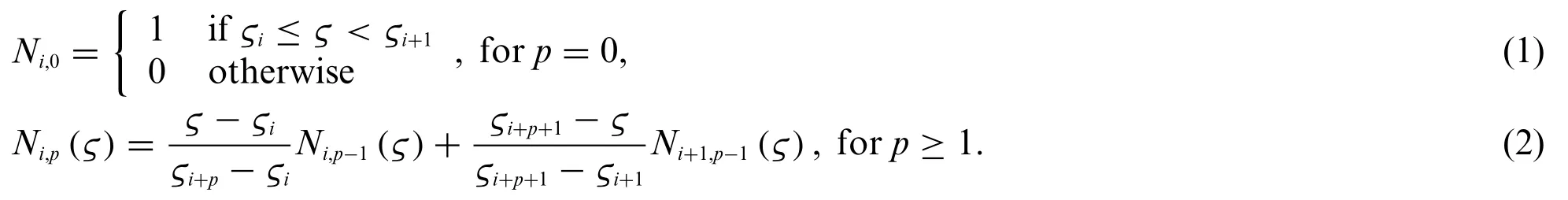
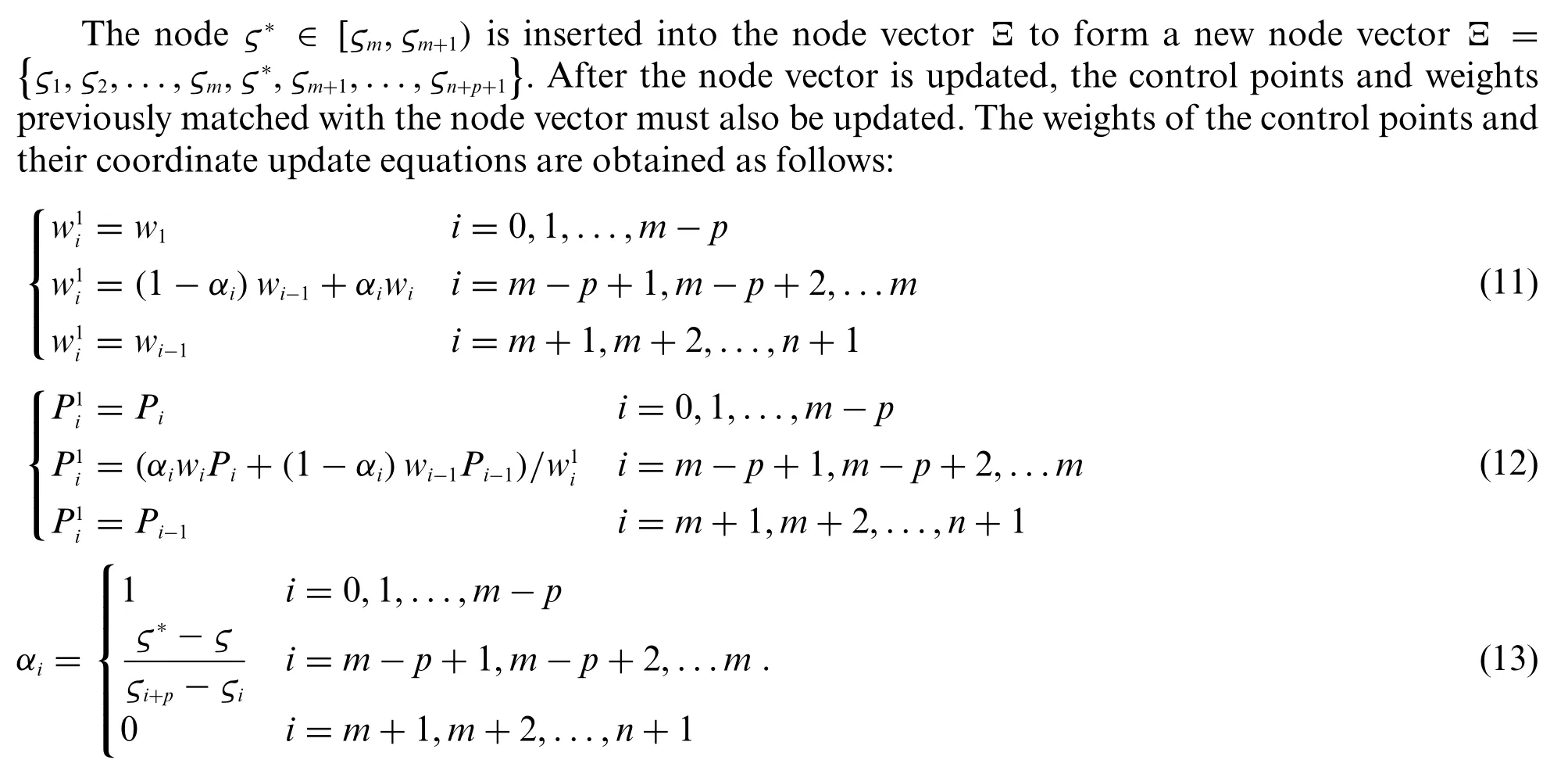
The B-spline basis function is composed of a non-subtractive real sequence of node values,called a node vectorΞ=(ςi≤ςi+1),whereςiis the node.pmaxis the highest polynomial order,and the number of basis functions is represented byn.After determining the B-spline basis function’s polynomial order,the node vector and the B-spline basis function group correspond one to one.Given the node vector,the B-spline basis function[40]is as follows:
The B-spline curve can be evaluated by basis function,and control point coordinates set{Pi}as

The B-spline curve can be extended to the B-spline surface.The node vectors of the two directions areand the control point isPi,j,wheremandnare unary basis functions in both directions,and the B-spline surface equation can be expressed as

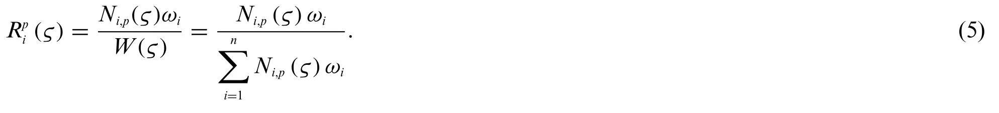
The quadratic NURBS basis functions and curves are shown in Figs.1a and 1b, respectively.According to the definition method of the B-spline basis function and the introduction of weight,the definition of the NURBS basis function is as follows:
The NURBS curve is defined as:

The NURBS surface can be obtained from the tensor product ofςandτin two coordinate directions:

,τ)is the basic function of the NURBS surface:
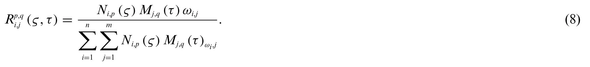
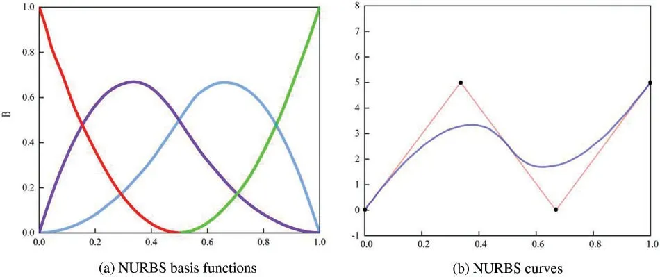
Figure 1:Quadratic NURBS basis functions and curves for a knot vector
2.2 Bézier Extraction Method
A sequence of NURBS basis functions is decomposed into linear combinations of Bernstein polynomials using the Bézier extraction procedure. Thus, the NURBS element is decomposed into a C0continuous Bézier element.The Bernstein polynomial is defined as[41]

whereB1,0(ς)≡1.
The expression of the Bézier curve is as follows:

The shape of the B-spline curve is the same as that of the Bézier curve if the existing nodes are inserted into the original B-spline’s node vector and the degree of repetition is equivalent to the curve’s order.At this time,the continuity of the curve and the continuity between the elements do not change[42].
The change of control point after node embedding is as follows:

According to the B-spline curve Eq.(3), the geometric parameters of the Bézier curve after embedding the nodes and the original B-spline curve are unchanged. Therefore, the NURBS curve is shown below:

We can deduce the link between the B-spline basis function and the Bernstein polynomial from the preceding equation.

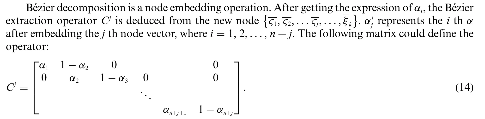
According to Eq.(19),Cis only related to node vectors and embedded new nodes, but not to control points or basis functions,so this extraction operator can also be used in NURBS.
For the denominator of the NURBS basis function,letand correlate withW(ς)as follows:

wherewb=CTw,wb(wis the weight of NURBS)is the weight of Bézier.Therefore,the basis function equation of NURBS using the Bézier extraction operator becomes

whereWis the diagonal matrix of weight. So the relationship between Bézier and NURBS control points is as follows:

2.3 Numerical Tests
A circular beam which is a cantilever beam is used as a numerical example to demonstrate the validity of both the classic IGA and the IGA based on the Bézier extraction method. At the free end, the beam is subjected to the specified displacementu0= -0.01. Fig.2 displays its geometry,boundary conditions,and material properties.The material is linearly elastic and under plane stress.Zienkiewicz et al.[43]provided an exact result for the strain energy of this circular beam.

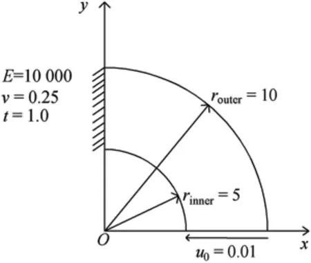
Figure 2:The geometry of the circular beam with material properties,boundary conditions and end shear
Fig.3 displays the NURBS and Bézier element meshes that were used to model the circular beam. The number of tangential elements was chosen to be twice the number of radial elements,both polynomials of order 2, and the IGA polynomial of order 1 was not considered, as this geometry cannot be modeled with a 1st-order NURBS surface.For the rigor of IGAvs.finite element comparison, the number of global degrees of freedom is made as close as possible to that of FEM,while still keeping the number of tangential elements double the number of radial elements.
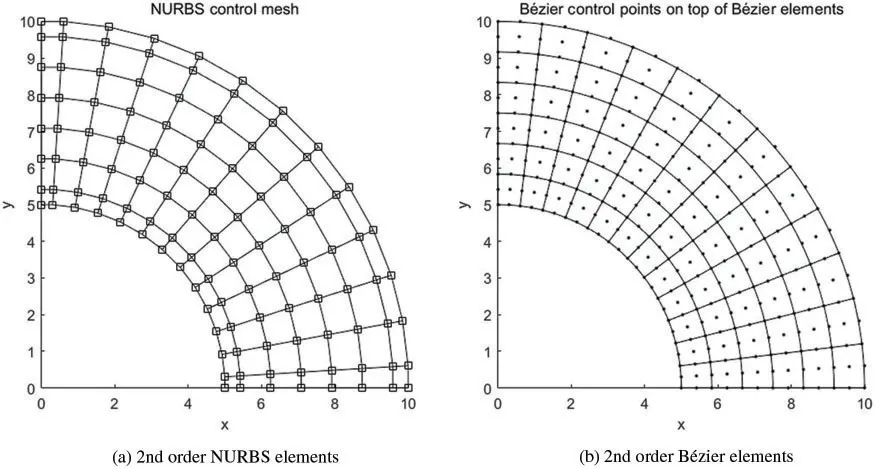
Figure 3:Circular beam,meshes of IGA,NURBS and Bézier physical mesh with control points
Table 1 shows the strain energy results to 14 decimal places for different grids and methods.The results of the three methods were validated by Zienkiewicz et al.[43].As expected,for approximately the same number of global degrees of freedom and the same order of elements,the IGA shows strain energy that is closer to the exact solution than the FEM.The results of the FEM using the Q4 element are the furthest,while the results using the traditional IGA and the IGA method based on the Bézier extraction are very close.
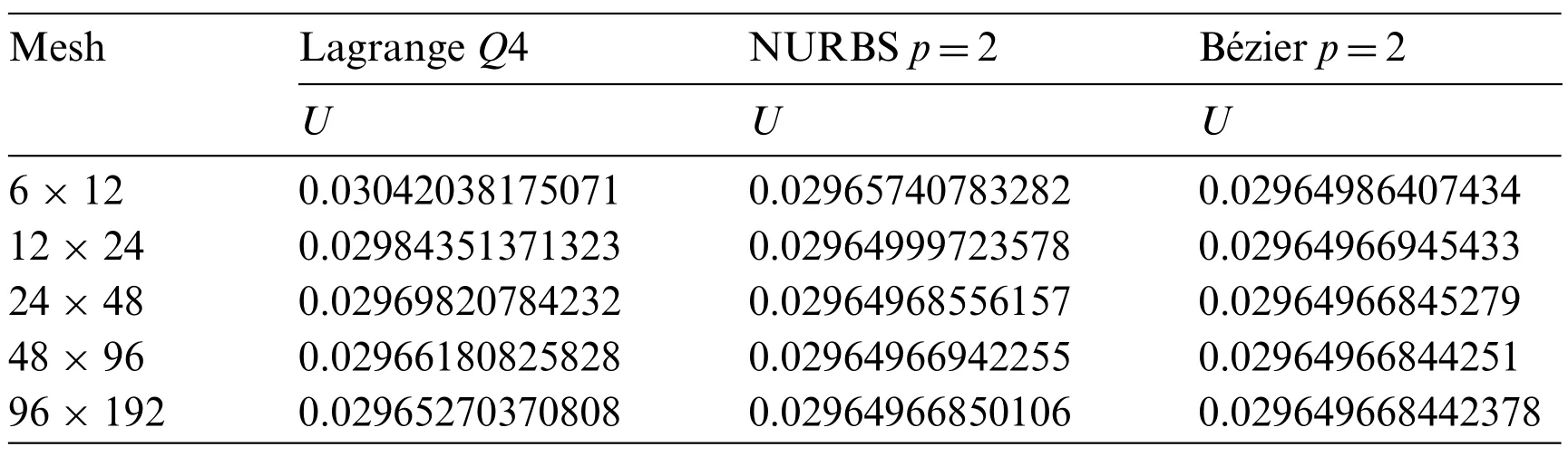
Table 1: The circular beam’s strain energy(precise answer U=0.029649668442377)
3 Isogeometric Equation for Winkler Foundation Beam
3.1 Basic Equation
The deformation of the elastic foundation beam and the soil is consistent under load.As per the elastic foundation’s local deformation law,as shown in Fig.4,the expressions of foundation reactionPfand deflectionωof foundation beam are as follows:

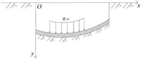
Figure 4:Winkler foundation model force diagram
kis the foundation reaction coefficient. After considering the strain energy, the total potential energy of the beam is as follows:

The first four terms on the right side of the equation are the strain energy of the beam, the distributed load potential energy, the concentrated load potential energy, and the concentrated moment load potential energy. WhereEIis the bending stiffness,q(x)is the distributed load,fpis the concentrated load, andMis the concentrated moment. The fifth itemis the contribution of foundation soil deformation energy to the total potential energy of a structural system.
After substituting Eq.(24)intoId,it is as follows:

The form of unit superposition is as follows:

Suppose the element displacement mode of the beam is as follows:

whereNanddare NURBS element shape functions and nodal displacement vectors,respectively.
Simultaneous Eqs.(27)and(28):

By substituting the total potential energy Eq.(25),the additional term of foundation stiffnessin the element stiffness matrix can be obtained by taking the extreme value.

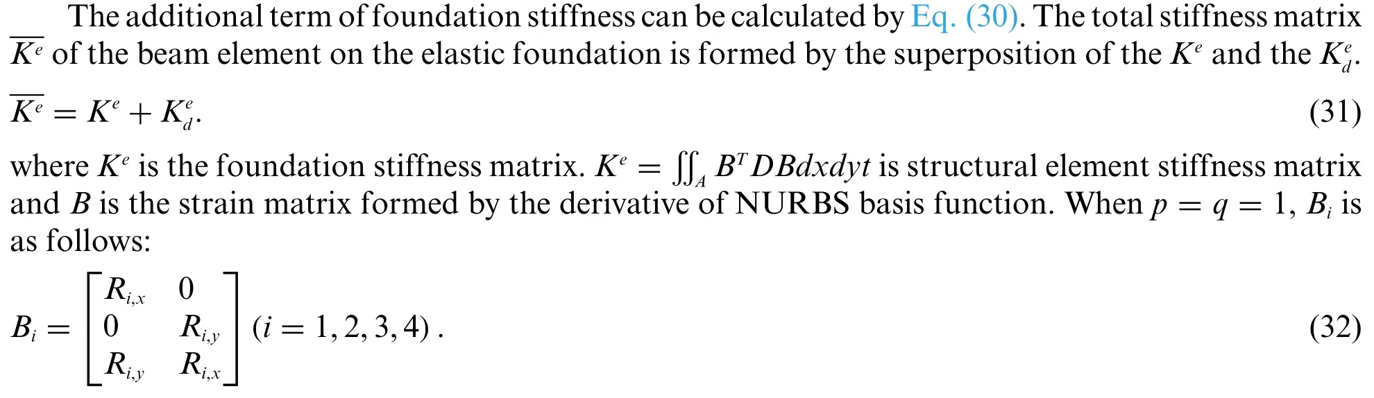
whereRi,xandRi,yare the partial derivatives of NURBS basis functions R toxandy,respectively.Dis a matrix of material constants.
The expressions of nodal force and nodal displacement of beams on elastic foundation under total stiffness are as follows:

whereδis the whole node displacement array,is the total stiffness matrix of the beam element andFis the whole node load array.
3.2 Numerical Integration of Equivalent Control Point Forces
The equilibrium differential equation of the element is as follows:

The right end of the equation is the equivalent internal force. The stiffness matrixof the control point is multiplied by the array of displacementδe. The left end is the equivalent external force,including the following concentrated force,surface force,and physical strength(only these three cases are considered in this paper). The stiffness matrixand external forceFcan be obtained by numerical integration.In order to simplify the force analysis of the element,the load of the element is moved to the control point according to the principle of static equivalence.
(1) Concentrated force: assuming that there is a concentrated loadat any control pointc,the equivalent external force is as follows:

(2) Surface force: there is a surface forceat a certain element boundary. The equivalent external force is as follows:


4 Verification
In this section,the bottom of the foundation is fully constrained,and the beam is coupled with the foundation.Therefore,this model does not consider the separation of the beam and the foundation.The structural parameters of beams on elastic foundations are shown in Table 2.

Table 2: Structural parameters of the beam on elastic foundation
Fig.5 shows the geometrical conditions of the elastic foundation beam and three different boundary conditions. Whereμis Poisson’s ratio andql= 382kN/mis the uniformly distributed load. A set of polynomial degreesp(p= 2,3,4) with fine meshes is used. Whenp= 2, the physical mesh and Bézier element mesh of the beam on the elastic foundation are shown in Fig.6.The beam is subjected to uniformly distributed loads,and the three boundary conditions are as follows:clamped at both ends (C-C), simply supported at both ends (S-S), and one end clamped and one end simply supported (C-S). Fig.7 depicts the displacement convergence of the beam’s centre point under an evenly distributed load and compared to the reference solution[44].It is clear that the IGA method is capable of solving the elastic foundation beam problem.The polynomial order affects the precision of convergence.
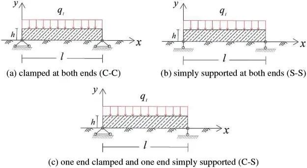
Figure 5:Boundary conditions of elastic foundation beams under uniformly distributed loads
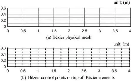
Figure 6: Elastic foundation beams meshing (8×8 meshing): (a) the Bézier physical mesh; (b) the Bézier control points
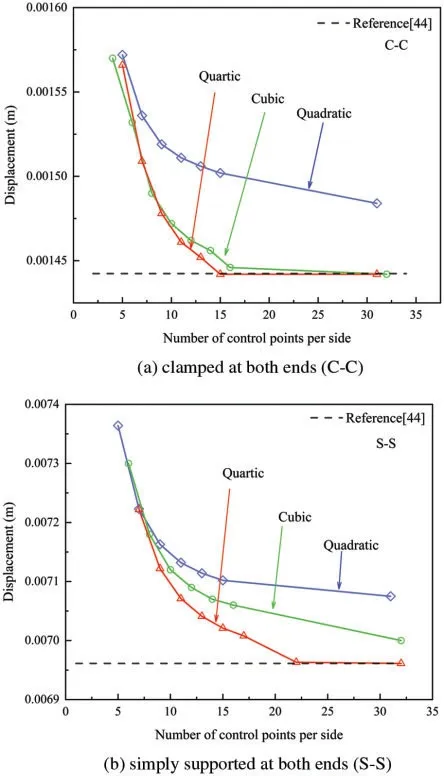
Figure 7: (Continued)
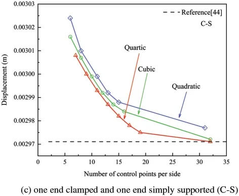
Figure 7:The beam’s displacement convergence of the middle point under an evenly distributed load and different boundary conditions
5 Application and Discussion
5.1 Equivalent Elastic Foundation Beam of Tunnel
This part investigates the deformation behaviour of the shield tunnel longitudinal structure,which serves as a reference basis for longitudinal design, using the equivalent continuous model and the theory of beam on elastic foundation. The actual tunnel structure is a tubular structure formed by bolted segments. The moment of inertia and bending stiffness of the section should be computed according to the actual section and material of the tunnel structure in order to simplify it to an elastic beam. The model assumes that tunnel materials are equally distributed in the transverse direction,and tunnel stiffness and structural features are the same as the simplified model in the longitudinal direction.The expression of equivalent elastic bending stiffness is as follows:

The following equation determines the position of the neutral axis:

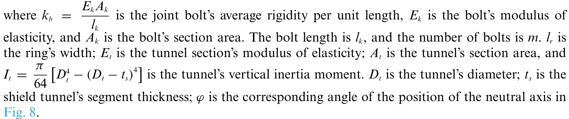
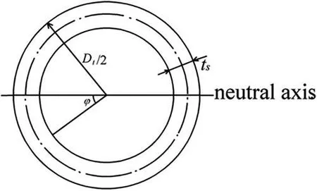
Figure 8:Schematic diagram of neutral axis position
5.2 Example of Tunnel Settlement
The two ends of a subway tunnel are connected with the station,and the soil at the front and rear of the entrance and exit section is reinforced byΦ800 mm cement jet grouting pile.The reinforcement range is 7 m on both sides,as shown in Fig.9.According to engineering experience in the Shanghai area,the reinforced foundation reaction coefficient isK1=5×10⁷N/m3,and the uniform foundation reaction coefficient isK2= 5 × 10⁶N/m3. The tunnel’s submerged depth is 10.3 meters, and the soil layer’s average bulk density is 18×103N/m3. The self-weight of the tunnel is 51×103Nper extension meter.Terzaghi earth pressure theory calculates the average linear load to be 1.2×10⁶N/m(excluding ground overloading).The tunnel has a 6200 mm exterior diameter and a 5500 mm interior diameter.There are 17 M30,8.8-grade bolts spread irregularly across the circumference.Table 3 shows the fundamental information about the segments and bolts. The elastic equivalent bending stiffness(EI)eq= 6.68×10¹⁰N·m2is computed using the equivalent continuous beam model,with the angle of the neutral axisφ=0.9635.
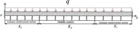
Figure 9:Interval tunnel calculation model
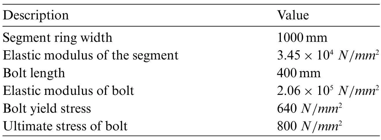
Table 3: The fundamental information of the segments and bolts
The length of the interval tunnel isL=42m.The foundation reaction coefficient is divided into three types.One is the homogeneous soil layerk1,the other is the homogeneous soil layerk2,and the last is shown in Fig.9.
(1) The foundation reaction coefficient isk1.
(2) The foundation reaction coefficient isk2.
(3) The foundation reaction coefficient isk2in the middle andk1at both ends.
The 10 × 10, 20 × 20, and 30 × 30 meshing of quadratic, cubic, and quartic Bezier elements is utilized in the computation to depict the displacement history of each control point of the tunnel model. The working condition combinations of three different foundation reaction coefficients are depicted in Figs.10-12. Fig.10 shows the comparison of the results of calculating the vertical settlement of the tunnel by the initial-parameter method [45] and the IGA method based on Bézier extraction under the different grid and basis function orders when the foundation reaction coefficient isk1.Figs.11 and 12 are similar to Fig.10.The foundation reaction coefficient in Fig.11 isk2,while the foundation reaction coefficient of the tunnel in Fig.12 isk2in the middle andk1at both ends.As shown in Figs.10a and 10b,when the foundation reaction coefficient isk1and the order of the basic function of the IGA is 2 and 3,there is a certain error between the calculation results and the results of the initial-parameter method.Compared to the corresponding graphs in Figs.11 and 12,the error is relatively small.

Figure 10: (Continued)
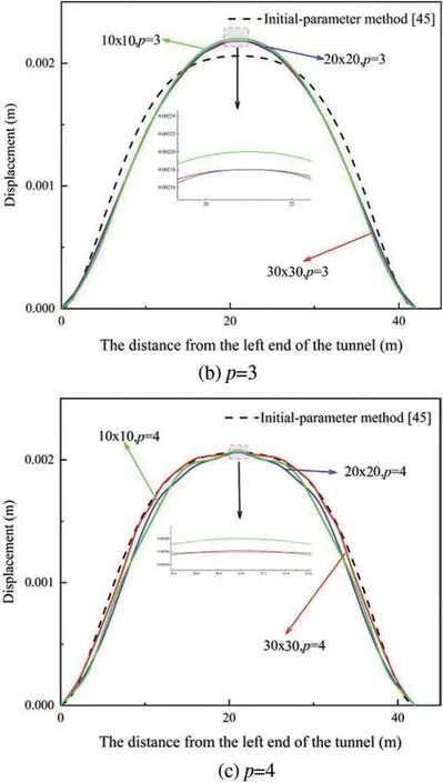
Figure 10:Interval tunnel loaded by a uniform pressure:displacement of each point and convergence to the initial parameter solution in the first situation
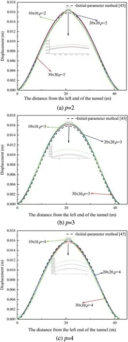
Figure 11:Interval tunnel loaded by a uniform pressure:displacement of each point and convergence to the initial parameter solution in the second situation
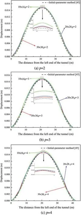
Figure 12:Interval tunnel loaded by a uniform pressure:displacement of each point and convergence to the initial parameter solution in the third situation
When the foundation reaction coefficient isk1,the deformation of the foundation is the smallest,when the foundation reaction coefficient isk2, the deformation of the foundation is the largest,and when the foundation reaction coefficient is the combination ofk1andk2, the distortion of the foundation is in the middle.Furthermore,when the calculated results are compared to the results of the initial-parameter method,the results suggest that utilizing a fine grid and a high-order polynomial calculation approach can result in higher precision data. Simultaneously, the data obtained by IGA and FEM are presented in Tables 4-9 to show the displacement of the tunnel model’s central point more clearly. As expected, the displacement given by IGA is closer to the exact solution than that shown by finite element analysis for roughly the same number of global degrees of freedom and the same order of elements.The higher-order element reduces the error.The finite element analysis with the Q4 element deviates the most from precise results,whereas the finite element analysis with the Q9 element is closer to the exact solution of the finest mesh.

Table 4:Interval tunnel loaded by a uniform pressure:vertical displacement f of the central point for different numbers of meshes and Bézier orders p(reference value f =0.002058 m)

Table 5:Interval tunnel loaded by a uniform pressure:finite element solution using different elements and different meshes
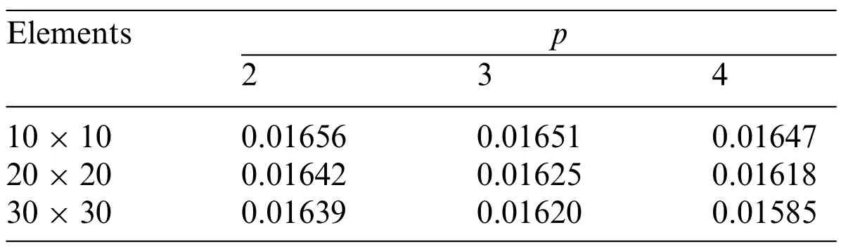
Table 6:Interval tunnel loaded by a uniform pressure:vertical displacement f of the central point for different numbers of meshes and Bézier orders p(reference value f=0.01586 m)

Table 7:Interval tunnel loaded by a uniform pressure:finite element solution using different elements and different meshes
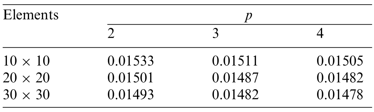
Table 8:Interval tunnel loaded by a uniform pressure:vertical displacement f of the central point for different numbers of meshes and Bézier orders p(reference value f =0.01476 m)
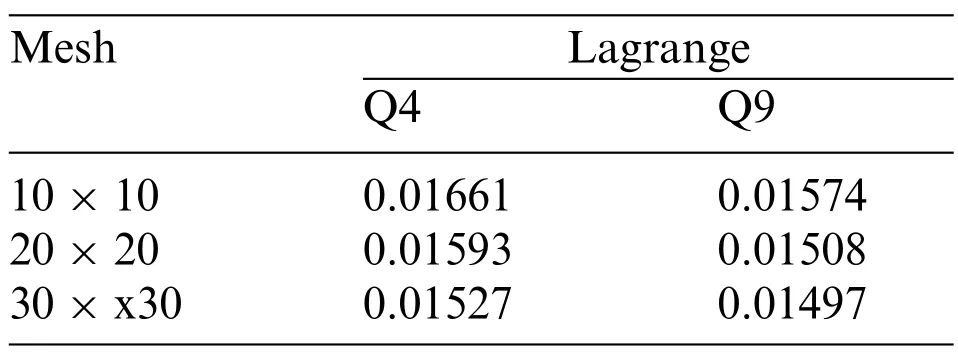
Table 9:Interval tunnel loaded by a uniform pressure:finite element solution using different elements and different meshes
6 Conclusion
The Bézier C0element is used to analyze the vertical displacement of beams on an elastic basis in this work.
(1) The investigation of the convergence and accuracy of vertical deformation of beams on elastic foundations under simple loads is established to validate the efficiency of this method.
(2) After obtaining the stiffness of the homogeneous cylinder from the equivalent continuous calculation model,the shield tunnel is simplified to a uniform continuous beam with equivalent stiffness.The simulation results are in good agreement with the initial-parameter solution,and the accuracy is higher than that of the FEM solution,providing a foundation for longitudinal design.
(3) The foundation reaction coefficient has a major influence on tunnel settlement,as shown by the comparison of the three different workings.
Acknowledgement:The authors gratefully acknowledge the support from the National Natural Science Foundation of China(52079128).
Funding Statement:The paper is supported by the National Natural Science Foundation of China(52079128).
Conflicts of Interest:The authors declare that they have no conflicts of interest to report regarding the present study.
 Computer Modeling In Engineering&Sciences2023年7期
- Computer Modeling In Engineering&Sciences的其它文章
- Edge Intelligence with Distributed Processing of DNNs:A Survey
- Turbulent Kinetic Energy of Flow during Inhale and Exhale to Characterize the Severity of Obstructive Sleep Apnea Patient
- The Effects of the Particle Size Ratio on the Behaviors of Binary Granular Materials
- A Novel Light Weight CNN Framework Integrated with Marine Predator Optimization for the Assessment of Tear Film-Lipid Layer Patterns
- Implementation of Rapid Code Transformation Process Using Deep Learning Approaches
- A New Hybrid Hierarchical Parallel Algorithm to Enhance the Performance of Large-Scale Structural Analysis Based on Heterogeneous Multicore Clusters