
Large-scale synthesis of 3D ordered microporous carbon at low temperature using cobalt ions exchanged zeolite Y as a template
2023-10-27 08:16ZHAOHongweiLILixiangZUOHuaiyangQUDiZHANGHanTAOLinSUNChengguoJUDongyingANBaigang
新型炭材料 2023年5期
ZHAO Hong-wei, LI Li-xiang,,*, ZUO Huai-yang, QU Di, ZHANG Han,TAO Lin, SUN Cheng-guo,3, JU Dong-ying, AN Bai-gang,,*
(1. Key Laboratory of Energy Materials and Electrochemistry Research Liaoning Province, School of Chemical Engineering, University of Science and Technology Liaoning, Anshan 114051, China;2. Hainan Provincial Key Lab of Fine Chemistry, School of Chemical Engineering and Technology, Hainan University, Haikou 570228, China.;3. School of Chemical Engineering, Nanjing University of Science and Technology, Nanjing 210094, China)
Abstract: Zeolite-templated carbons (ZTCs) have a unique three-dimensional (3D) ordered microporous structure and an extralarge surface area, and have excellent properties in adsorption and energy storage. Unfortunately, the lack of efficient synthesis strategies and the difficulty of doing this on a large-scale have seriously limited their development. We have developed a large-scale simple production route using a relatively low synthesis temperature and direct acetylene chemical vapor deposition (CVD) using Co ion-exchanged zeolite Y (CoY) as the template. The Co2+ confined in the zeolite acts as Lewis acid sites to catalyze the pyrolysis of acetylene through the d-π coordination effect, making carbon deposition occur selectively inside the zeolite at 400 °C rather than on the external surface. By systematically investigating the CVD temperature and time, the optimum conditions of 8 h deposition at 400°C produces an excellent 3D ordered-microporous structure and outstanding structure parameters (3 000 m2 g-1, 1.33 cm3 g-1). Its CO2 adsorption capacity and selectivity are 2.78 mmol g-1 (25 °C, 100 kPa) and 98, respectively. This simple CVD process allows the synthesis of high-quality ZTCs on a large scale at a low cost.
Key words: Zeolite-templated carbon;Cobalt ion-exchanged;Low temperature chemical vapor deposition;Ordered microporous;CO2 adsorbent
1 Introduction
Nanoporous carbons are one of the hottest topics in physics, chemistry, and materials science. In the past 30 years, many novel carbon nanomaterials with unique structures and properties have emerged, including CNTs, graphene, graphdiyne, graphite-like porous carbon, and carbon nanocages[1-5]. The practical and potential applications of nanoporous carbons in adsorption, catalysis, energy, environment, sensors,and optoelectronic devices aroused great interest in academia and industry[5-10]. Various properties of porous carbon materials are highly related to their nanostructure[11-13]. Much effort has been made to design and tune the nanostructure, especially the pore structure of carbon materials[14-16]. However, it remains a significant challenge to accurately construct the pores that are ordered distribution in three dimensions (3D)and with a pore size of about 1.0 nm in carbon materials. Zeolite, as a crystalline porous material with a well-defined molecular level, has been attracting much attention owing to its micropore size and ordered distribution in 3D[17]. It would be fascinating if such an ordered microporous structure of zeolite could combine with the advantages of carbon materials, such as good conductivity, mechanical flexibility,and facile chemical modification[18-25]. Duplicating zeolite by using itself as a template is an ideal route to get the carbon material with an ordered nanostructure.The bottlenecks are making carbon precursors filling into the zeolite pores with tiny sizes and obtaining a stable and ordered pore structure constructed by carbons after template removal. The first successful attempt to synthesize zeolite-templated carbons (ZTCs)was made by Kyotani’s group in 1997[26]. They first used the impregnation of zeolite with furfuryl alcohol(FA) or propylene CVD method to prepare ZTCs, but the quality was poor[26]. Subsequently, they further optimized the preparation conditions and successfully obtained high specific surface areas (SSA) of 3000-4000 m2g-1by a two-step method (FA impregnation followed by CVD)[27-29]. However, almost 5 days for molecular filling and polymerization causes a long time to consume, making the commercial application of ZTCs impossible from the view of technology,yield and cost.
Compared with the strict and time-consuming process of filling and polymerizing small organic molecules to prepare ZTCs, direct CVD technology is easy to control and can continuously produce carbon materials and thus attempt to prepare ZTCs. The technique of direct CVD to synthesize ZTCs was first reported by Kyotani’s group, the SSA of ZTCs is 2 760 m2g-1by acetylene CVD at 600 °C[30]. Nonetheless,direct CVD technology still faces poor structural integrity, the high cost caused by high temperatures, and the inability to prepare high-quality ZTCs on a large scale, thus limiting its practical application. Therefore,if the carbon precursor could be selectively deposited into the zeolite pores at a temperature lower than its pyrolysis temperature in the CVD process, it is beneficial for the large-scale preparation of high-quality ZTCs. In our previous works, the silanization method enhanced the activity of carbon deposition onto the wall of pores of the zeolite Y template. Direct CVD of acetonitrile vapor successfully synthesized N-doped ZTCs with ordered microporous structures[31]. Although this method failed to resolve the problem of high-temperature CVD, it suggests that modifying the zeolite template could be a valid route to improve the nanostructure of ZTCs as prepared by a direct CVD.
Among the works using template modification to improve the nanostructure of carbon materials, Ryoo’s group contributed a pioneering study[32-33]. They made La3+cations embedded in zeolite pores by the ion exchange method. The embedded La3+as catalytic sites make carbon-containing precursors pyrolyzed selectively inside the pores without the coke on the external surface of zeolite at a temperature as low as 600 °C.As a suitable Lewis acid catalyst, the transition metal cation would bond with hydrocarbon molecules through d-π coordination. Using the transition metal ions (Co2+, Mn2+, Cu2+and Ni2+) exchanged zeolite as a template, microporous carbon with well orderedstructure in 3D can be produced by the direct CVD of ethylene or acetylene accompanied with water vapor[34]. Cobalt and its compounds are the most commonly used catalysts for synthesizing carbon materials. In principle, Co ions have vacant d orbitals in the electron shell structures. Thed-πinteractions directly stabilize hydrocarbons and catalyze the formation of carbon frameworks during pyrocondensation without other additional conditions. Using Co2+ion-exchanged zeolite as a template, ZTCs with ordered nanostructure were synthesized by CVD of ethylene,adding water vapor at 600 °C[34]. However, introducing water vapor in the CVD process caused the oxidation of carbon to produce the oxygen-containing groups around the porous carbons. Consequently, it induces the decreases in pore orderliness and SSA.
Herein, the ZTCs with good nanostructure prepared using Co2+ion-exchanged zeolite as a template by the direct acetylene CVD as shown in Scheme 1.The pyrolysis of acetylene and carbon deposition into micropores of CoY zeolite efficiently operated at a temperature as low as 400 °C, which is a lower temperature for synthesizing ZTCs than the traditional CVD methods. By optimizing the preparation parameters, the optimal ZTC(Co)-400-8h (Co2+ion-exchanged zeolite as template and acetylene 8 h CVD at 400 °C) owns an excellent 3D ordered-microporous structure and significant SSA (3 000 m2g-1), the improvement of structural integrity is beneficial to improve the CO2adsorption capacity and selectivity. The simple CVD technology also allows a large-scale synthesis of high-quality ZTCs, up to 10.0 g CoY zeolite could be replicated into high-quality ZTCs.
2 Experimental
2.1 Chemicals and reagents
The NaY zeolite (SiO2/Al2O3≥ 5.3, Na2O ≤12.5%) was obtained from Nanjing XFNANO Materials Tech Co., Ltd. Cobalt sulfate heptahydrate(CoSO4·7H2O, ≥ 99.5%), hydrochloric acid (HCl, 5.0 mol L-1), hydrofluoric acid (HF, ≥ 40%) were purchased from Sinopharm Chemical Reagent Co., Ltd.Ultrapure acetylene (C2H2, ≥ 99.999%), nitrogen (N2,≥ 99.999%), argon (Ar, ≥ 99.999%) and carbon dioxide (CO2, ≥ 99.999%) were supplied by the Anshan Angang gas Limited Liability Company.
2.2 Synthesis of Co ions-exchanged zeolite
Co2+exchange was performed using 3.0 g Y zeolite in 0.1 mol L-1180 mL aqueous solution of CoSO4. The mixed solution was kept at 60 °C for 3 h under reduced pressure, and the treatment process of ion exchange was repeated twice. The resulting slurry was filtered and thoroughly washed with distilled water and then dried for 12 h in a vacuum oven at 80 °C.The name of the sample is CoY zeolite (before calcination). Then, CoY zeolite was calcined at 550 °C for 4 h in the air again.
2.3 Preparation of ZTCs by NaY and CoY zeolite
The ZTCs were synthesized using acetylene as a carbon source and NaY and CoY zeolite as a template,respectively. In a typical carbon synthesis process by chemical vapor deposition (CVD), 0.4 g of CoY (or NaY) zeolite was placed in a horizontal quartz reactor(50 mm inner diameter), and the air purged by pure Ar gas flow at room temperature with 1 h in the reactor.The CVD temperature of the synthesis device was heated up to 700 °C (CoY zeolite from 700 to 200 °C,and NaY zeolite from 700 to 500 °C, respectively,samples were collected every 100 °C) under pure Ar gas flow with a heating rate of 5 °C min-1. Then acetylene gas (10% in Ar, acetylene: 5 mL min-1; Ar: 45 mL min-1) was passed through the reactor for 1 h.After the carbonaceous deposition, the graphitization temperature was increased to 900 °C and was maintained for 1 h under pure Ar gas again. After cooling to room temperature, the carbon compounds indicated as C/NaY-A-1h and C/CoY-A-1h, where the A denoted the CVD temperature (°C). Finally, the carbon composite of C/CoY-A-1h was treated with HF/HCl mixture solution to liberate the carbon product from the zeolite template. The final product was obtained by purifying with deionized water and drying in a 80°C vacuum oven for one night. Finally, carbon samples were named ZTC(Co)-A-1h. In addition, another set of carbon samples was synthesized by CoY zeolite through CVD at 400 °C with different CVD times (2, 4 and 8 h) of carbon deposition in the same synthesis device. Before and after HF/HCl mixture solution treatment, the samples were C/CoY-400-B and ZTC(Co)-400-B, respectively, where the B denoted CVD time (h). For the large-scale synthesis of ZTC(Co), only the mass of CoY zeolite and CVD conditions were changed: the 10.0 g of CoY zeolite placed in a horizontal quartz reactor, and length,width, and height were 100, 17.5, 17.5 mm, respectively; 8 h at 400 °C CVD temperature (acetylene gas:30 mL min-1, Ar gas: 30 mL min-1); 1 h at 900 °C graphitization temperature under pure Ar gas (100 mL min-1). The final large-scale synthesized carbon sample was named ZTC(Co)-400-8h(L).
2.4 Characterization
Thermogravimetric analysis (TGA, TA SDTQ600, the ceramic crucible, heat rate of 10 °C min-1in the air) was conducted due to the different water absorption capacity of the samples. The weight loss (%)of the samples is different at room temperature to 300 °C, so the TG curves of carbon contents were collected in the range of 300 to 900 °C. The morphology and structure of the catalysts were characterized using scanning electron microscopy (SEM, FEI Apreo, operated at 1 kV) and transmission electron microscopy(TEM, FEI Talos F200X, operated at 200 kV). The powder X-ray diffraction device (XRD, X’pret Powder, Rigaku D/MAX-2500X, CuKα) and Raman spectrometer (HORIBA Xplora Plus, excited by 532 nm laser) were used to characterize the ordered structure and graphitization degree of samples. X-ray photoelectron spectroscopy (XPS, SHIMADZU, AXIS SUPRA, AlKα) was used to analyze the chemical states of samples. N2adsorption measurements were measured at liquid nitrogen temperature (-196 °C) using a volumetric sorption analyzer (Micromeritics,ASAP 2020). Before the N2adsorption measurements,all samples were outgassed for 6 h at 300 °C in a vacuum. The specific surface area (SSA) was determined according to the Brunauer-Emmett-Teller (BET)method using adsorption data points in the pressure range of 0.01-0.05. Pore size distributions (PSDs) and pore volume were determined using non-local density functional theory (NLDFT), assuming the slit-shaped pore geometry. The micropore (Vmicro) volume was determined from the NLDFT cumulative volumes in the pore diameter range ofd≤ 2 nm. The volume of the total pore (Vtotal) was determined atp/p0= 0.96.
2.5 Adsorption experiments
Static CO2and N2adsorption tests of samples were measured on a Micromeritics ASAP 2020 instrument under the pressure of 0-100 kPa at 0, 25 and 50°C after samples that had been degassed at 120 °C for 12 h. The CO2adsorptions were measured on a range of temperatures (0, 25 and 50 °C) and pressures (0-100 kPa) with 20 mg samples. Meanwhile, the N2isotherms were measured at 25 °C and pressures (0-100 kPa) with 20 mg samples. The adsorbed quantities(mmol g-1) were calculated from the measured pressures after equilibrium arrived. The isosteric heat of adsorption (Qst) was from adsorption isotherms at 0,25 and 50 °C, with the Clausius-Clapeyron equation[35]. The adsorption selectivity of CO2/N2was obtained from CO2and N2isotherms at 298 K. The selectivity was calculated for CO2/N2=15/85 (up to 100 kPa) with ideal adsorbed solution theory (IAST) by using the free software[36]. The isotherms were fitted with the "Dual-site Langmuir-Freundlich Model" for selectivity calculations.
Dual-Site Langmuir-Freundlich (DSLF):
whereqis the adsorbed amount per mass of adsorbent (mmol g-1),Pis the pressure of bulk gas pressure at equilibrium status (kPa),q1andq2are the saturation capacities (mmol g-1),k1andk2are the affinity coefficients,n1andn2are the isotherm model parameter.
Assuming a binary gas mixture containing component 1 and component 2, the IAST selectivity (S)was defined as the following:
whereq1(q2) andp1(p2) are the mole fractions of components 1 and 2 in the adsorbed and bulk phases.
3 Results and discussion
3.1 Preparation and structure of Co ion-exchange template
As shown in Fig. S1a, the color changes of zeolite samples could be observed through the photographs. The color of NaY zeolite changes from white to pink after the process of Co2+ion exchange and then turns to purple after 550 °C heat treatment. It indicates a successful ion exchange since the color of low concentrations of Co2+is pink. After the heat treatment, the residual water in the zeolite template was evaporated completely, resulting in the increase of the concentration of Co2+, and thus template turned purple. The X-ray photoelectron spectra (XPS) of the NaY and CoY zeolite are shown in Fig. 1a. In the CoY zeolite, Co 2p characteristic peak appears at 783.6 eV[37-38]. Accordingly, the peak intensity of Na 1s at 1 072.5 eV is weakened. It can be inferred that Co elements replace a part of Na elements in NaY zeolite after ion exchange, which proves that the Co element has been successfully exchanged into the zeolite. Small-angle XRD was used to investigate whether the process of preparing CoY zeolite would affect the original ordered pore structure of the zeolite. All zeolite samples contain (111) diffraction peaks around 2θof 6°-7°, as shown in Fig. 1b, which proves that the intrinsically ordered nanostructure of zeolite was not destroyed by the modification processes[39-40]. After calcination, the more substantial peak of (111) zeolite indicates a higher structural order of CoY zeolite. The characteristic peaks of metallic Co were not observed in CoY zeolite (before calcination) and CoY zeolite (Fig. 1c), which indicates a stabilized Co2+in the zeolite skeleton. All zeolite samples have similar morphology from the SEM observation (Fig. 1d-f), suggesting that the ion exchange process does not change the CoY zeolite inherited from the NaY zeolite template. In addition, there are no apparent metal clusters on the surface of CoY zeolite.
The N2adsorption isotherms of NaY and CoY zeolite are shown in Fig. S2a. Two samples have the type I isotherm characteristics representing the microporous materials[41-42]. The pore sizes of NaY and CoY zeolite concentrated at 0.7-1.0 nm, and the primary pore size of CoY zeolite is slightly smaller than NaY zeolite (Fig. S2b). The SSA and pore volume of CoY zeolite (572 m2g-1, 0.28 cm3g-1) are also slightly lower than that of NaY zeolite (649 m2g-1, 0.33 cm3g-1), as shown in Table S1. The main reason is that the heat treatment of 550 °C was used to stabilize the structure of CoY zeolite, it also resulted in the pore contraction of CoY zeolite.
3.2 The activity and efficiency of Co ion-exchange template for carbon deposition
The CVD temperature is crucial in ensuring pyrolysis and deposition of carbon precursors into CoY zeolite pores. Here, a direct CVD of acetylene using CoY and NaY zeolite as a template was carried out. The effects of CVD temperature (from 700 to 200 °C) on the pyrolysis of acetylene and carbon deposition were investigated. With the temperature decrease of acetylene CVD from 700 to 200 °C, the appearance color of C/CoY-A-1h (‘A’ means CVD temperature) samples were still black even at 300 °C(Fig. S1b). In contrast, the C/NaY-A-1h sample only turned brown at 500 °C (Fig. S1c), indicating that the CoY zeolite as a template has a higher carbon deposition activity than the NaY template. The effects of CVD temperature on carbon deposition into the zeolite template were further analyzed by TGA(Fig. 2a and S3). Using NaY zeolite, a valid carbon deposition only occurs at 600 °C, and carbon deposition is 10.3% (mass fraction) after 1 h. However, the deposition amount of carbon reaches 9.8% (mass fraction) even at 300 °C using CoY zeolite. Such a low temperature for carbon deposition is far lower than the temperature required by the conventional CVD method to synthesize carbon materials using acetylene precursors (ca. 600 °C) and propylene (ca. 700°C)[30,43-45]. In addition to a low temperature for the active deposition of carbon, using CoY zeolite as a template can also enhance the efficiency of carbon deposition. At the same CVD temperature, the deposition efficiency using CoY zeolite was significantly higher than NaY zeolite. As Moon et al. proposed in synthesizing 3D microporous carbon using Co ion-exchanged zeolite by CVD, Co2+as the Lewis acid sites could form d-π coordination with acetylene[34]. Therefore, the CVD temperature for valid carbon deposition decreases, and the corresponding deposition efficiency increases. The Co2+embedded in zeolite plays a critical catalytic site for acetylene pyrolysis and carbon deposition. The CVD temperature is also a key factor affecting the nanostructure of ZTCs.
After acid treatment, the XRD tests were used to analyze the structure of ZTC(Co)-A-1h samples prepared at different temperatures. The weak characteristic peak at the low angle region around 2θof 6°-7° is visible for all samples except ZTC(Co)-700-1h and ZTC(Co)-300-1h (Fig. 2b), which indicates the existence of a few completely ordered microporous structures. Furthermore, compared to the other samples, the 2 broad weak peaks representing carbon (002) and(10) around 26° and 44°, are hardly observed for ZTC(Co)-400-1h[46,47](Fig. 2c). After acid treatment, the ZTC(Co)-400-1h still showed a similarly particular morphology as the zeolite template (Fig. 2d-f).
3.3 Microstructure analysis of ZTCs
Raman spectra of all ZTC(Co)-A-1h samples were deconvoluted into 4 components (Fig. S4). The corresponding curve-fitting results and the intensity ratio of theDandGbands (ID/IG) are shown in Fig. S5.Combined with TGA, XRD and SEM, the lowID/IGof ZTC-400-1h suggests that the ZTC(Co)-400-1h has a good graphitization degree, which could be attributed to a large number of carbide-like compounds produced by the CVD process and growing along the active nano-channels inside the zeolite template rather than the random growth of CNTs outside the zeolite at the higher CVD temperature. The TEM image(Fig. S6) shows the relatively well-ordered microporous structure of the ZTC(Co)-400-1h. Notably, the ordered micropores are open, and carbon layers do not cover the outer surface. The acetylene was selectively deposited onto the active pore wall of CoY zeolite at a CVD temperature of 400 °C.
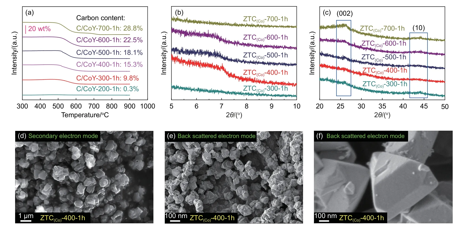
Fig. 2 (a) Amount of carbon deposition in the NaY and CoY zeolite plotted as a function of the different temperatures with using acetylene/Ar gas for 1 h.(b) Small-angle and (c) wide-angle XRD patterns of all ZTC(Co)-A-1h samples. SEM images: (d) Secondary electron and (e, f) back scattered electron images of ZTC(Co)-400-1h
Pore structure and SSA of ZTC(Co)-A-1h samples were examined by N2adsorption isotherms. All ZTC(Co)-A-1h samples contain a high adsorption capacity atp/p0≤ 0.1, suggesting their characteristic of microporous structure (Fig. 3a). ZTC(Co)-400-1h exhibited the highest adsorption capacity atp/p0≤ 0.1,demonstrating the highest microporous porosity, the most significant SSA of 2 200 m2g-1and total pore volume of 1.00 cm3g-1(Table S1). The PSD of Fig. 3b further illustrated the microporous feature of ZTC(Co)-A-1h samples. Their pore size focuses on 1.2 nm, which results from the reverse replication of zeolite skeleton into carbon micropores. The pores distributed around 1.7-3.0 nm were ascribed to a part of zeolite pores that could finally interconnect after the acid treatment. Therefore, ZTC(Co)-400-1h has an ordered pore structure. It could be extrapolated that the Co ions in CoY zeolite catalyze the acetylene conversed into the unstable carbide-like compounds at low temperature of 400 °C through d-π coordination and polymerization. After the heat treatment, the carbide-like compounds could be transformed into the stable solid carbon along the ordered microporous channels under the limitation of the template, thus forming a stable three-dimensional carbon structure.Although the SSA of ZTC(Co)-400-1h has shown the orderliness of pore structure, the short CVD time of 1 h did not get the full carbon deposition into the pores of CoY zeolite. To obtain the highly ordered ZTCs with a large SSA, a reasonable amount of carbon deposition is a requisite by controlling the CVD time. The pore size around 1.7-3.0 nm are ascribed to a part of zeolite pores that could finally interconnect after the acid treatment. Therefore, ZTC(Co)-400-1h has an ordered pore structure. It could be extrapolated that the Co ions in CoY zeolite catalyze the acetylene conversed into the unstable carbide-like compounds at low temperature of 400 °C through d-π coordination and polymerization. After the heat treatment, the carbide-like compounds could be transformed into the stable solid carbon along the ordered microporous channels under the limitation of the template, thus forming a stable three-dimensional carbon structure.Although the SSA of ZTC(Co)-400-1h has shown the orderliness of pore structure, the short CVD time of 1 h does not get the full carbon deposition into the pores of CoY zeolite. To obtain the highly ordered ZTCs with a large SSA, a reasonable amount of carbon deposition is a requisite by controlling the CVD time.
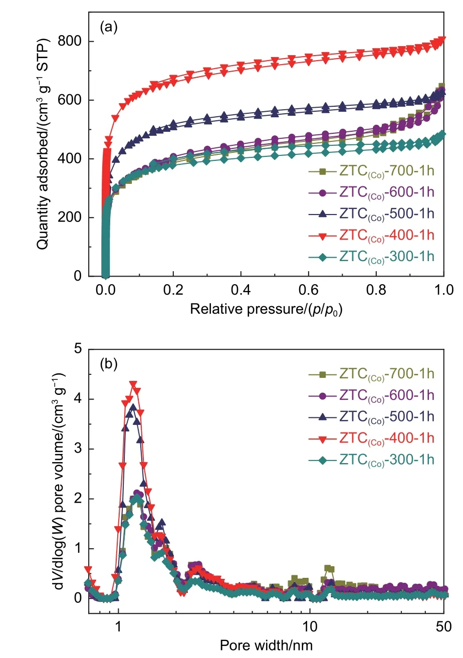
Fig. 3 (a) N2 adsorption-desorption isotherms and (b) NLDFT pore size distribution of different ZTC(Co)-A-1h samples
3.4 Optimization of the ordered structure of ZTCs
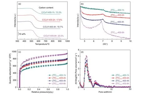
Fig. 4 (a) TGA curves of C/CoY-400-1h, C/CoY-400-2h, C/CoY-400-4h and C/CoY-400-8h. (b) Small-angle XRD patterns, (c) N2 adsorption-desorption isotherms and (d) NLDFT pore size distribution of ZTC(Co)-400-1h, ZTC(Co)-400-2h, ZTC(Co)-400-4h and ZTC(Co)-400-8h
Carbon amount filling into the zeolite template is an essential factor in constructing a stable and ordered microstructure of high-quality ZTCs, which was feasible to prepare ZTCs by CVD at 400 °C. However, it needs further study on how CVD time influences the carbon deposition amount and the resulting microstructure of ZTCs. The time of CVD to prepare ZTCs was extended from 1.0 to 8.0 h, respectively. As shown by TGA curves in Fig. 4a, carbon content of the sample increases with CVD time. When CVD time was prolonged to 8.0 h, the carbon amount of C/CoY-400-8h could be up to 20.5% (mass fraction).The uniformly dispersed Co sites in the zeolite template could provide catalytic activity for the low-temperature acetylene carbonization, and the pore of template remains open for the entrance of carbon precursor molecules. The carbon loading amount could achieve a high standard for building a robust and ordered microporous framework[25]. After the template removal, the small-angle and wide-angle XRD patterns of samples as shown in Fig. 4b and S7. The diffraction peak intensity of ZTC(Co)-400-8h at 2θof 6°-7° representing the ordered pore arrangement is significantly enhanced, suggesting that the increased carbon amount is mainly concentrated in the interior of the template to build the ordered and stable microporous structure. In the wide-angle XRD results(Fig. S7), the (002) peaks of the samples from ZTC(Co)-400-1h to ZTC(Co)-400-8h showed no changes significantly. It proves again that there is no deposition of dense carbon layers around the external surface of CoY zeolite. The N2adsorption isotherms and PSD curves (Fig. 4c-d) of samples demonstrate that ZTC(Co)-400-8h has more micropores focused on 1.2 nm. As summarized in Table 1, the SSA and pore volume of ZTC(Co)-400-8h could be up to 3 000 m2g-1and 1.33 cm3g-1, respectively. The high SSA and large pore volume are attributed to a more complete,internally ordered micropore structure.
As Raman spectroscopy shown in Fig. S8, theID/IGvalue of ZTC(Co)-400-8h (ID/IG=0.88) is slightly higher than the other samples. This abnormal phenomenon suggests an increase of defects and edge sites in the graphite structure of ZTCs. As a template,zeolite has a 3D interconnected pore with a pore size of less than 1.2 nm. It reversally duplicates that ZTCs with a well-ordered structure are constructed by the graphene layer with a large domain size deposited in-side zeolite channels, which leads to many distortion sites at the pore junctions[48]. It is equivalent to a classical 2D sp2carbon network transformed into a 3D distortion network. The distortion locations are considered defects in graphite structure, which is why ZTC(Co)-400-8h has the better-ordered structure but more “defects”. Furthermore, the distortion locations could result in more edge sites that are easily bonded with O species. As shown by the XPS survey spectra of samples (Fig. S9), the prominent peaks of carbon(C 1s, 284.1 eV), oxygen (O 1s, 531.6 eV), and fluorine (F 1s, 688.8 eV) elements could be observed in all samples[34], the residual fluorine elements could be introduced by acid treatment. ZTC(Co)-400-8h owns the highest oxygen content of 6.7 at% among the samples(Table S2).
The morphology and microstructure of ZTC(Co)-400-8h are observed by SEM and TEM shown in Fig. 5. The extension of the acetylene intake time to 8 h does not change the morphology of ZTCs inheriting from the CoY zeolite template. The sharp edges and corners of particles suggest less carbon deposition around the external surface of the template. As shown in TEM images, the higher carbon filling into the template improves the structural order degree of ZTC(Co)-400-8h. The ordered distribution of micropores could be more clearly observed from the directions along and vertical the pore channels. The results further demonstrate that the ZTCs with highly ordered structures could be obtained by optimizing CVD time.
3.5 CO2 adsorption property of ZTCs
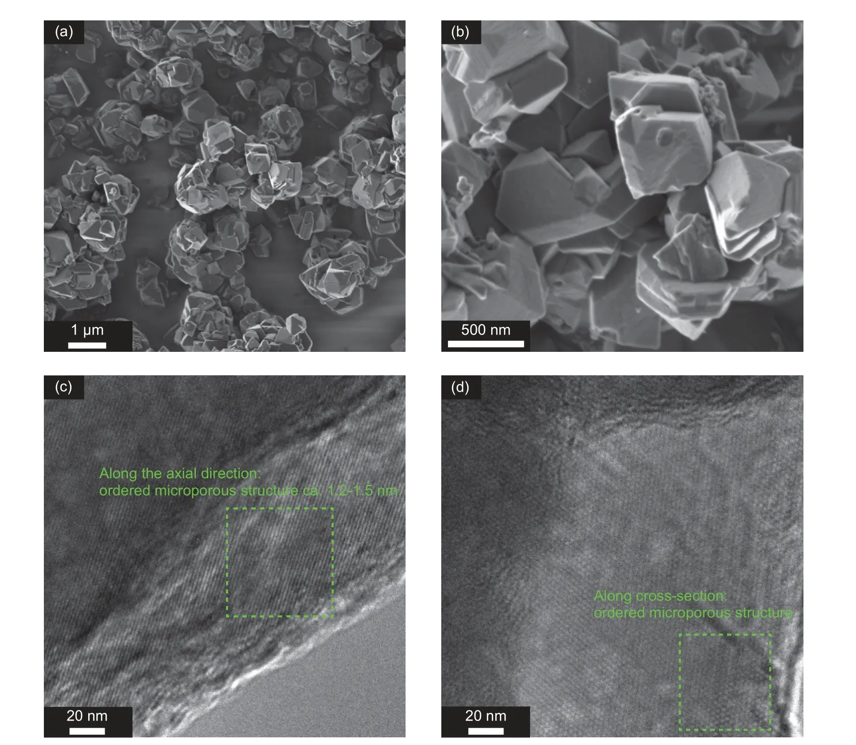
Fig. 5 (a, b) SEM images of ZTC(Co)-400-8h, (c, d) TEM images of ZTC(Co)-400-8h with different viewing directions
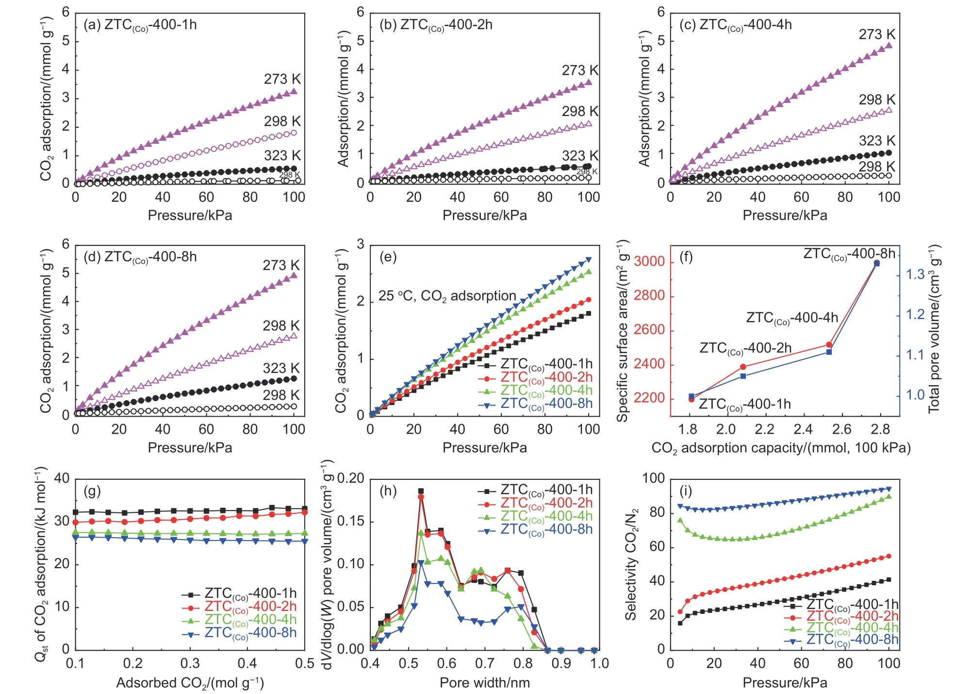
Fig. 6 (a-d) CO2 adsorption isotherms (0, 25 and 50 °C) and N2 adsorption isotherms (25 °C, black hollow circular). (e) Comparison of CO2 adsorption properties at 25 °C. (f) Analysis of the plot of CO2 adsorption capacity, specific surface area (red), and total pore volume (blue). (g) Isosteric heat of CO2 adsorption(Qst). (h) Pore size distribution (0.4-1.0 nm) derived from CO2 adsorption isotherm (0 °C) by NLDFT method.(i) CO2/N2 selectivity calculated using IAST at 25 °C
Porous materials are widely used in the field of CO2storage and separation. Developing an application of ZTCs prepared by the CoY zeolite template, its CO2adsorption ability was investigated and evaluated by static CO2and N2adsorption tests. The adsorption isotherms of samples (Fig. 6a-d) show that the CO2adsorption capacity of all samples is much higher than their N2adsorption capacity, which is due to the higher quadrupole coupling and the faster gas diffusion rate of CO2than N2molecules, the CO2adsorbate could more effectively overcome diffusion obstacle and enter smaller pores under the same adsorption condition[49-51]. In addition, CO2adsorption capacity decreases gradually with increasing temperature (0 to 50 °C), which could be attributed that the Langmuir parameterbdecreases as temperature increases and the gas adsorption capacity also decreases according to the Langmuir adsorption model[52]. As shown by Fig. 6e, ZTC(Co)-400-8h exhibits the highest CO2uptake (2.78 mmol g-1), which should be attributed to the higher surface area (3 000 m2g-1) and pore volume (1.33 cm3g-1) than other samples (Fig. 6f).Furthermore, the 3D ordered micropore structure of ZTC(Co)-400-8h can provide more available channels for CO2diffusion and storage. Meanwhile, the ZTC(Co)-400-8h contains more distortion locations and edge termination sites, which might change the electron density of the pore channel surface and enhance the electrostatic adsorption capacity. Investigating the strength of interaction between CO2molecules and ZTC(Co)-400-B samples, the isosteric heat of adsorption (Qst) was calculated by fitting CO2adsorption isotherms at 0, 25 and 50 °C for each sample (Fig. 6g).The stability ofQstvalue at the initial adsorption stage(0.1-0.5 mol CO2small loading) reflects the excellent interaction strength between CO2and all sorbent samples. In contrast, theQst(ca. 26 kJ mol-1) of ZTC(Co)-400-8h is slightly lower than other samples.The reason may be that the ZTC(Co)-400-8h has the more complete 3D ordered microporous channels and lacks the small micropore (0.4-0.9 nm) caused by the pore structural collapse. The PSDs derived from CO2adsorption isotherm (0 °C) are shown in Fig. 6h. The micropores (0.4-0.9 nm) in the ZTC(Co)-400-8h are less than the other samples. However, the heat of gas adsorption has a significant positive correlation with the content of micropores within 0.4-0.8 nm[53]. Fig. 6i shows the selectivity of ZTC(Co)-400-B samples for mixed gases of CO2/N2with a volume ratio of 15/85 using IAST[37]. All ZTC(Co)-400-B samples show a growing tendency of CO2selectivity with increasing pressure. ZTC(Co)-400-8h contains the most significant SSA and the best-ordered microporous structure among the tested samples. Its CO2selectivity reached 98%, significantly higher than the other samples.Meanwhile, as an unmodified pure carbon material,ZTC(Co)-400-8h has higher CO2capacity and selectivity than some pure/heteroatom-doped carbon material under atmospheric pressure due to its good structural characteristics[54-57], which makes it a potential adsorbent for CO2removal from N2in post-combustion flue gases.
3.6 ZTCs preparation on a large scale
Owing to the advantages of low synthesis temperature and simple CVD technology, it is promising to realize a large-scale synthesis of ZTCs by the present method. Herein, the amount of CoY zeolite template was increased from 0.4 to 10.0 g for batch production of ZTCs. The CVD using a mixture gas of Ar (30 mL min-1)/C2H2(30 mL min-1) with a high acetylene ratio was carried out for 8.0 h. Fig. 7a-e show photographs of the CoY zeolite bed before and after the CVD. After CVD, the black powders in the quartz boat indicate that an effective carbon deposition on large amounts of CoY templates could be achieved, although the amount of CoY zeolite was increased by 25 times. It can be noted from Fig. 7c-d that the quartz tube wall remains transparent even after 8.0 h acetylene CVD, suggesting that good catalytic activity of CoY zeolite could ensure a large number of carbons deposited into the template. According to the TGA results (Fig. S10), the carbon deposition of C/CoY-400-8h(L) is approximately 23.4% (mass fraction), which is enough to construct an ordered carbon framework, the production of ZTC(Co)-400-8h(L)is ca. 3.0 g after the acid treatment. The XRD pattern(Fig. 7f) is much similar to that of the ZTC(Co)-400-8h small-batch prepared, suggesting an ordered microporous structure of the sample. The SSA and pore volume (Fig. S11) of ZTC(Co)-400-8h(L) is 2 700 m2g-1and 1.27 cm3g-1, respectively. Table S3 summarizes the synthesis temperature, using the amount of template and parameters of ZTCs as prepared by the CVD method reported in the literature. The present technology to produce ZTCs has the advantages of the lowest CVD temperature, higher yield, and good quality. Therefore, it is highly promising to produce zeolite-templated carbon materials for mass production in a simple but energy-efficient way.
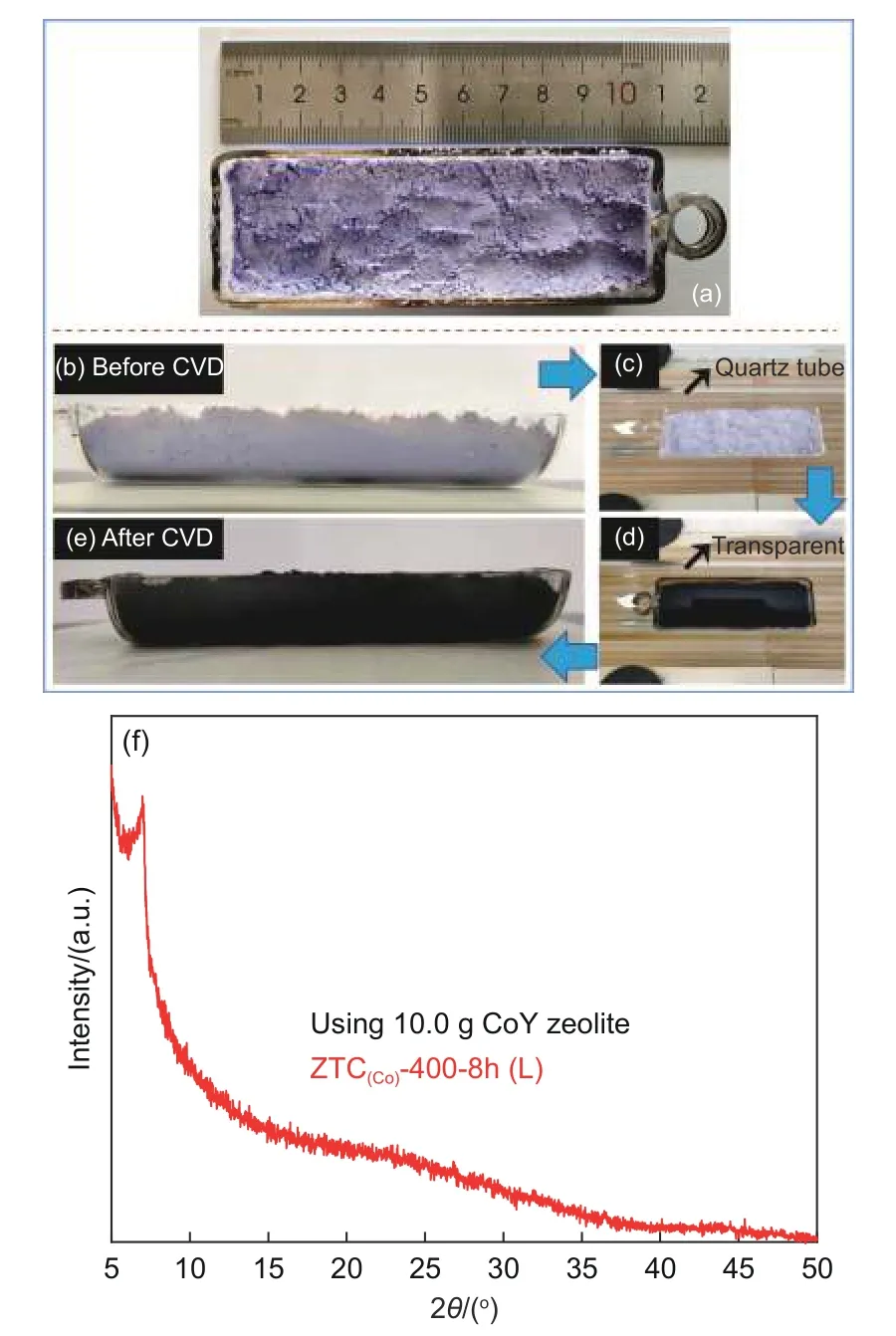
Fig. 7 (a-e) Photographs of quartz reactor for large-scale synthesis filled with a thick bed of CoY zeolite (10.0 g) sample.(f) XRD pattern of ZTC(Co)-400-8h(L)
4 Conclusions
A large-scale technology to synthesize the ordered microporous carbon by acetylene CVD at a temperature as low as 400 °C using Co ion-exchanged zeolite as the template has been successfully developed. As the catalytic sites, the Co ions embedded into the template could make acetylene decompose and selectively deposited in zeolite pores at low temperatures to avoid the unselective deposition of carbons on the outer surface of the template by traditional high-temperature CVD. Furthermore, increasing the CVD time could improve the carbon content and stability of the ordered microporous carbon skeleton in the zeolite template optimal sample of ZTC(Co)-400-8h owns a 3D-ordered microporous structure,large surface area (3 000 m2g-1), and pore volume(1.33 cm3g-1). Owing to the highly ordered pore structure, ZTC(Co)-400-8h is a potential adsorbent for CO2capture, the uptake of CO2and CO2/N2selectivity is 2.78 mmol g-1(25 °C, 100 kPa) and 98%, respectively. In order to increase the potential for commercial application of this technology, the synthesis of high-quality ZTCs on a large scale by using a 10.0-g batch of CoY zeolite has been demonstrated successfully. In summary, the present technology to produce ZTCs has the advantages of low synthesis temperature, suitable for large-scale synthesis, and is easy to control.
Data availability statement
The data that support the findings of this study are openly available in Science Data Bank at https://www.doi.org/10.57760/sciencedb.j00125.00019 or https://resolve.pid21.cn/31253.11.sciencedb.j00125.00019.
Acknowledgements
We acknowledge the financial support by grants from the National Natural Science Foundation of China (51872131, 51972156, 51672117, 51672118),the distinguished professor project of the education department of Liaoning, the Startup Fund for Doctoral Research of Liaoning (2023-BS-184), and the University of Science And Technology Liaoning Talent Project Grants (6003000315).

- 新型炭材料的其它文章
- Development of biochar electrode materials for capacitive deionization: preparation, performance, regeneration and other challenges
- Highly efficient Co—N—C electrocatalysts with a porous structure for the oxygen reduction reaction
- Reversible surface modification of PAN-based carbon fibers by a ferrocene-based surfactant
- Recent advances in 3D interconnected carbon/metal high thermal conductivity composites
- Synthesis and electrochemical properties of nano-Si/C composite anodes for lithium-ion batteries
- Factors that influence the performance of hydrogen detectors based on single-wall carbon nanotubes