
一种控制微涡轮叶尖泄漏流的新技术
2011-04-19 10:38曹传军黄国平
曹传军 黄国平 夏 晨
(南京航空航天大学能源与动力学院,南京,210016,中国)
INTRODUCTION
Micro turbine engines(MTEs)have advantages of light weight,large power and density of energy.So it can be widely used in many fields of military and civil.Micro turbine whose characteristic scale is centimeter or millimeter is one main part of M TE and plays an important role in its performance.The efficiency of micro turbine is obviously lower than that of traditional one according to the current design level[1](presently, the efficiency of micro turbine is about 80%,and traditional turbine is 88%—91%).The efficiency of turbine declines when its scale decreases.The loss of tip clearance leakage is a key factor which holds back improvement of turbine performance. The researches[2]on traditional engine show that the loss caused by leakage flow of tip clearance is roughly equal to one-third of total turbine stage loss.As the tip clearance increases by 1%,the efficiency of turbine decreases by 1.5% and the specific fuel consumption(SFC)rises by 3%.But there are many difficulties for production and assembly of micro turbine engine.For this reason, the ratio of tip clearance and blade span of micro turbine almost reaches 10%,far larger than that of traditional turbine(only 1%—2% for traditional turbine).So the influence of tip leakage flow on micro turbine is more visible than that of traditional one.It is a crucial problem to study the influence of leakage flow on micro turbine and propose an effective method for reducing leakage flow to improve the performance of micro turbine engine.
A kind of active clearance control technology is used in advanced traditional engine at present[3].It uses the air from compressor to heat or cool turbine blade or case working in different conditions,and directly controls the size of tip clearance.There are some difficulties to apply this method to micro engine,such as complex control law,design of air-bleed piping,weight increase,thermal inertia,and low rate of heat exchange.Ref.[4]inducted air through by-pass and ejected it from blade tip towards pressure surface to reduce leakage flow.Ref.[5]buried plasma actuators in blade tip and made the air ionized.Ionized air flows backwards leakage flow in the force of electrical field to reduce leakage. These two methods also have shortcomings when they are applied to the micro engine.Method for bypass entraining makes the design and the structure complex.In addition,it depresses the reliability of engine.Plasma actuators method needs fresh supplier.It is only a kind of method on research,and far away from actual application.
A new technique for controlling tip leakage flow of micro turbine by using backward vortex generators(BVGs)is proposedin this paper.It is applied for Chinese patent of invention(Application number is 200910232890.8).The flow of BVGs jets backwards at high velocity from the blade tip surface to the block leakage flow.There is no need for extra air-bleed piping.Most of all, it has obvious effect for reducing leakage flow.
1 SKETCH OF BVG DESIGN AND KEY FACTORS
The flow of pressure side is forced to suction surface by pressure difference between pressure and suction sides.It interacts with traverse flow in mainstream,thus forming leakage vortex in turbine passage.The leakage vortex becomes big and strong as it flows towards downstream.It blocks mainstream and causes loss of energy. Then the work ability and efficiency of turbine are reduced.So if some methods are used to block the leakage flow leaking into mainstream and make more fluid expand in turbine passage,the harmful influence on turbine performance caused by leakage flow decreases.
The methods of active tip control technology and extra air-bleed piping for controlling leakage flow mentioned at the beginning of this paper have some difficulties when they are applied to the micro turbine.The flow is assumed to be directly used in mainstream and jet backward to leakage flow for blocking leakage flow.The flow velocity near pressure surface is extremely low so the static pressure is high.Futhermore,when fluid in tip clearance flows to suction side,the velocity increases and the static pressure decreases. Big pressure difference exists between pressure surface and blade tip.As a result of this pressure difference,BVG forces the fluid flowing from the pressure side to the blade tip and jetting backward to leakage flow,thus forming high speed flow for blocking leakage(Fig.1).To increase the mass of BVG and improve the effect of reducing leakage flow,some key factors should be noticed,including the centerline position of inflow and outflow holes,the outflow angle,the diameter ratio of inflow and outflow holes,and the position of BVGs in blade tip.

Fig.1 Structure of BVG
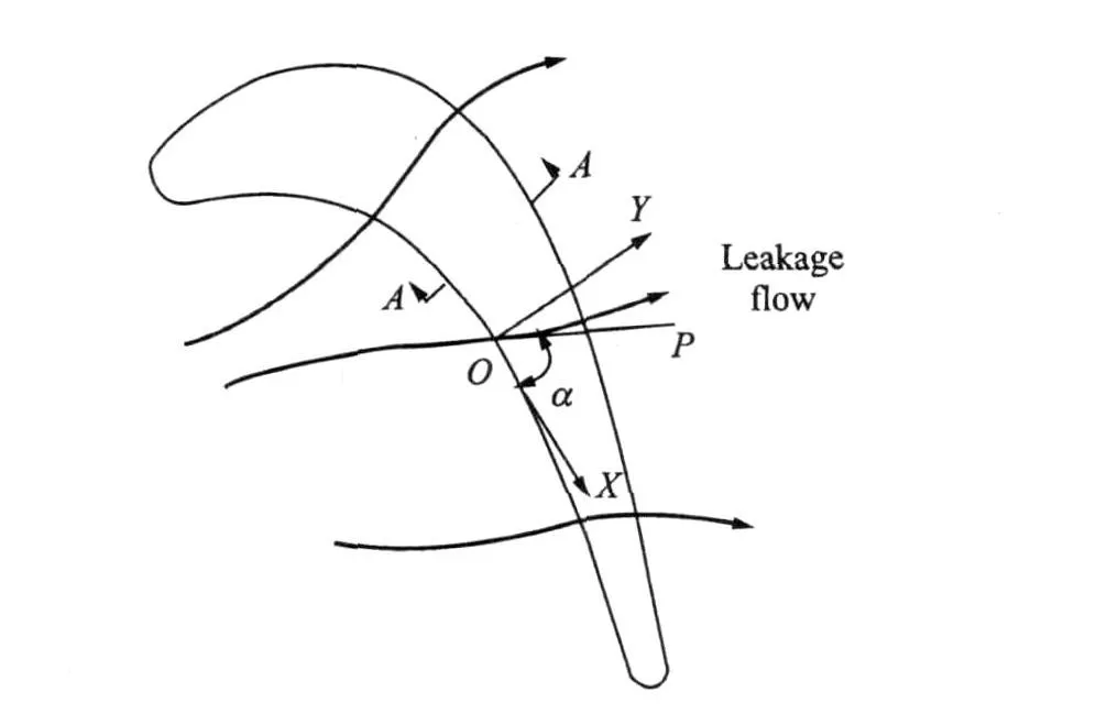
Fig.2 Direction of leakage flow and centerline position of BV G
(1)Centerline position of inflow and outflow holes of BVG.A coordinate system is found on blade tip surface(Fig.2).Point"O"is the crossing of leakage flow and curve of pressure surface. "OX"and"OY"denote the tangent line and the exterior normal line of pressure surface curve at point"O",respectively."OP"denotes the tangent line of leakage flow velocity at point"O", which is the direction of leakage flow velocity."T" is the angle of"OP"and"OX",and defined as the position parameter of centerlines of inflow and outflow holes of BVG.For reducing the leakage flow maximum,the centerline sections of inflow and outflow holes of BVG are made vertical to blade tip.And projection of the section on blade tip surface lies along the direction of leakage flow that is the direction of"OP".Under different inlet conditions,the direction of leakage flow is not the same.To the ratio of tip clearance and blade span described in this paper,numerical study shows thatTis 60—80°when the inlet Mach number varies from 0.2 to 0.3.The effect of reducing leakage flow is improved if the suitable Tis chosen under different inlet conditions.
(2)Outflow angle of BVG."OM"and"ON" are the centerlines of inflow and outflow of BVG (Fig.1).Uis the outflow angle and it defined as the direction of outflow and blade tip.SmallerU can improve the ability of reducing leakage flow. However,whenUis too small it makes flow angle of turning increase and bring more flow loss. Eventually,it decreases the mass of BVG and depresses the effect of reducing leakage flow.OptimizedUis 30—45°according to numerical study.
(3)Diameters of inflow and outflow holes of BVG.Bigger diameter of inflow hole can increase mass of BVG.Smaller diameter of outlet flow hole can increase the outflow velocity of BVG and improve the ability of reducing leakage flow. Taking the cascade in this paper for example,as the diameter ratio of inflow and outflow holes is 2,the outflow center velocity of BVG reaches the high subsonic and the inlet velocity of turbine cascade is only low subsonic.Therefore,the diameter ratio of inflow and outflow holes makes a larger outflow velocity of BVG.
(4)Position of BVGs in blade tip.The numerical study shows that the velocity of leakage flow along the blade chord in tip clearance differs a lot.In the middle and rear parts of blade tip, the velocity of leakage flow is larger.So arranging the BVGs in the suitable position can improve the control effect of leakage flow.
This method of BVG directly uses the flow near pressure surface in turbine passage to jet backwards from blade tip for reducing leakage flow.It can decrease the mass of leakage flow and leakage loss together with the interaction strength of leakage flow and mainstream.Therefore,the more fluid works in turbine passage,the turbine efficiency is higher.This method eliminates the needs for additional design of air-bleed piping and arrangement.It saves space and decreases the weight.The structure of BVG is simple and easy to be applied.
2 BVG DESIGN FOR MILLIMETER LEVEL TURBINE CASCADEAND GRID GENERATION
BVGs arranged in blade tip for a millimeter level turbine cascade is designed.The chosen original cascade is a typical turbine rotor cascade[6],and a lot of experimental researches are performed by using this cascade[6-9].This cascade is scaled to millimeter level in this paper.According to the requirements of experimental design and condition,the blade geometrical and aerodynamic parameters are as follows:chord 9.11 mm; axial chord 7.44 mm;pitch 7.11 mm;span 6.69 mm;and inlet flow angle 44.7°.The height of passage is 7.36 mm.The ratio of tip clearance and blade span is 10%.
Twenty three BVGs in total are arranged in the middle and rear parts of blade tip(Fig.3). According to the fourth key factoranalyzed above,arranging BVGs in middle and rear parts of blade tip is better for reducing tip leakage flow.The entrances of BVGs distance from blade hub by 93% the blade span.Position parameter (T)of all BVGs is 70°.Outflow angle(U)is 35°. Angle of inflow and outflow direction is 80°.The diameter ratio of inflow and outflow holes is 2. The diameters of inflow and outflow holes are 0.2 and 0.1 mm,respectively.BVGs have simple structures and are easy to be made.The inflow and outflow holes are straight and can be made by micro electrical discharge machining(M-EDM). This technology is developed maturely.The diameter range of hole made with good quality even reaches ten micrometers level.
The grid is unstructured and generated by ICEM.The grid of only one cascade passage is generated and simulated owing to the period boundary condition.There are 3.30× 10⁵grid cells for case without BVGs and 5.69×10⁵cells for case with BVGs(Fig.4).Solving method is coupled and implicit.Turbulence model is two equations of realizable κ-X.Total temperature of entrance flow is 300 K and total pressure is 156.3 kPa.The fluid is ideal air.Numerical simulations are perfomed with/without BVGs at inlet Mach number of 0.293.The influence of BVGs on the flow fields and the performance of cascade is analyzed at the given Mach number.

Fig.3 Perspective contouring of blade with BV Gs

Fig.4 Grid distribution of blade cascade in case with BVGs
3 NUMERICAL INVESTIGATION OFTURBINESWITH AND WITHOUT BVGs
3.1 Streamlines and flow structures of axial cross-sections
Figs.5-7 are the streamlines,distributions of total pressure,Mach number and static pressure of cross-section at 80% axial chord,respectively. The inlet Mach number is 0.293,and inflow mass is 6.546 g/s.According to numerical results in this paper,the influence of BVGs on tip clearance leakage flow is analyzed and compared to the case without BVGs in the same inflow mass.Fig.5 shows there is a high loss area of total pressure near blade tip.The leakage flow interacts with traverse flow in turbine passage and forms leakage vortex.The jet produced by BVGs strongly interacts with tip clearance leakage flow.Compared to the case without BVGs,one higher loss area forms in half tip clearance near blade tip in the case with BVGs.In the influence of BVGs, total pressure loss in the center of leakage vortex is higher than that without BVGs,but the size of leakage vortex is smaller.BVGs have little influence on half tip clearance near the end wall.

Fig.5 Streamlines and total pressure distributions of cross-section at80% axial chord
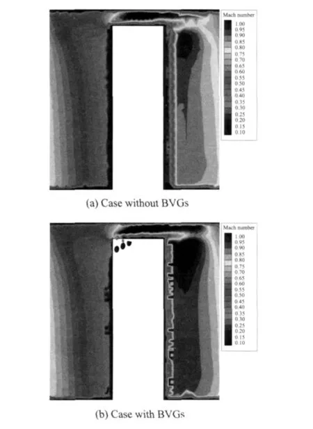
Fig.6 Mach number distributions of cross-section at 80% axial chord
Fig.6 shows that the jet from BVGs interacts with leakage flow and forms considerably low velocity flow in half tip clearance near blade tip.It is why BVGs can reduce the leakage flow obviously.The jet holds back the leakage flow and makes effective flow passage area of leakage flow smaller.The mass in half clearance near top wall is nearly constant,then the velocity of leakage flow becomes bigger,which is observed by comparing the position nearend wall in Fig.6. Whether there are BVGs or not in blade tip,the Mach number of suction side near blade tip is larger than that in the other places near suction surface.It is due to the leakage flow which leaks into passage and lets flow mass in part of passage increase.It contracts the stream tube and makes the Mach number or the velocity increase in part of passage.The average Mach number in mainstream near suction side with BVGs is larger than that without BVGs by about 3%.There are two reasons:(1)BVGs decrease tip clearance leakage flow by 0.84% compared with the total inflow mass.Following the mass conservation equation, when there is little change in total pressure and flow area,the average Mach number in mainstream increases by 1.5%—2%.(2)Compared with the case of BVGs,the influence area of leakage vortex is larger in the case of no BVGs. Mainstream flows deviating to the pressure surface because it is coiled and extruded by the leakage vortex.Compared with the case of BVGs,the flow angle of lag increases by 0.5— 1°in the case of no BVGs.Increase of flow lag angle makes the effective flow area grow by about 0.5% and the Mach number decrease by about 1%.For the reason of increased Mach number,the loss of total pressure grows when the fluid flows through the suction surface and the total pressure becomes smaller in the case of BVGs(Fig.5(b)).Decrease of the total pressure and increase of the Mach number make the static pressure near suction surface smaller(Fig.7(b)).
Compared Fig.7(a)with Fig.7(b),the static pressure in half passage near the pressure side hardly changes.Near the entrance of BVGs,the pressure decreases a little.There are two low pressure areas caused by leakage flow near suction side at the top of blade.Pressure in center of the two low pressure areas is lower in the case with BVGs than that without BVGs.Jet of BVGs interacts with the leakage flow and forms the low pressure area in half tip clearance near blade tip. One part of the low pressure flow carried by leakage flow with high velocity near the top wall interacts with the traverse flow in turbine passage and forms the leakage vortex.Compared with the case without BVGs,the center pressure is lower in the case with BVGs because of carrying low pressure flow near blade tip.The other part of low pressure flow leaks into suction side and forms the other low pressure area near the tip of suction surface.

Fig.7 Pressure distributions of cross-section at 80%axial chord
3.2 Streamlines and Mach number distributions of S1 surface in tip clearance
Fig.8 is the Mach number distributions of S1 surface at inlet Mach number 0.293.Figs.8(a, b)are the streamlines and the Mach number distributions of S1 surface which distances from blade tip by 70% of the tip clearance.Figs.8(c, d)are the streamlines and the Mach number distributions of S1 surface which distances from blade tip by 10% of tip clearance.Figs.8(a,c) represent the case without BVGs and Figs.8(b, d)represent the case with BVGs.Compared with 10% surface(which means the distance of S1 surface from blade tip is 10% of the tip clearance), the velocity of leakage flow is larger at 70% surface.Compared streamlines at 70% surface with 10% surface,the flow at 70% surface flows to the suction surface with high velocity in the direction of nearly vertical to mean camber line;however,the flow at 10%surface is influenced by the blade tip heavily.It flows to the suction surface with low velocity in the direction deviating to mean camber line and leaks into passage closely in the direction of main flow.Comparing streamlines and Mach number distributions with/without BVGs,it is found that BVGs have little influence on 70% surface but a lot on the surfaces near blade tip.The jet of BVGs makes the leakage flow deflect a lot and velocity of leakage flow decrease.It results in the reduced influence of leakage flow on main flow in turbine passage.Compared with that in the case without BVGs,the flow velocity of mainstream increases in the case with BVGs.This is because the effective flow area decreases and it makes the velocity near the end wall of tip clearance increase in the case with BVGs.When leaking into passage,it increases the velocity in mainstream.
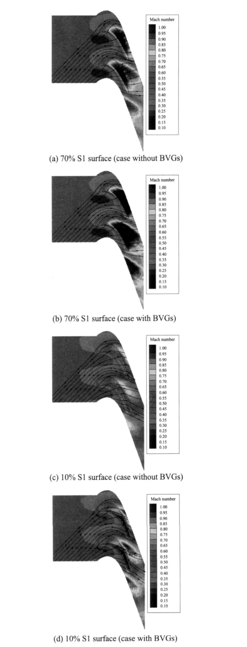
Fig.8 Streamlines and Mach number distributions of S1surface
3.3 Streamlines and total pressure distributions at centerline section of BVG hole
Fig.9 is streamlines and total pressure distributions at the centerline section of BVGhole with inlet Mach number 0.293.The seventeenth BVG is chosen for analysis.The interaction of BVG and leakage flow makes inlet flow streamlines of leakage rise up and then the effective flow area decreases.A high loss area is found behind BVG near blade tip surface. The leakage flow with high lossleaksinto suction sideandmakes the loss of total pressure near blade tip increase(Fig.9 (b)).
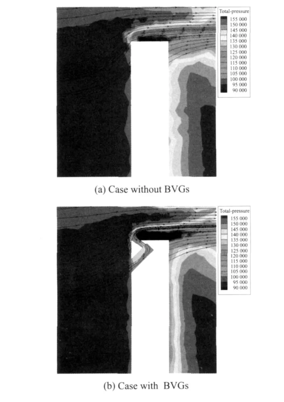
Fig.9 Streamlines and total pressure distributions at the centerline section of BVG hole
3.4 Static pressure distributions of blade tip surface and suction surface
Fig.10 is the static pressure distribution of blade tip surface and suction surface.In the interaction of BVGs and leakage flow,a low pressure area forms near blade tip when fluid flows from pressure side to suction side(Fig.10(b)).One part of low pressure flow leaks into suction side and makes a large low pressure area on suction surface near blade tip.The average Mach number increases and the total pressure decreases in main flow passage because ofreduced leakage by BVGs.So the static pressure on suction surface with BVGs is smaller than that without BVGs.
The static pressure on suction surface decreases visibly with BVGs is the main reason of improving blade circumferential load when the static pressure on pressure surface is nearly unchanged.
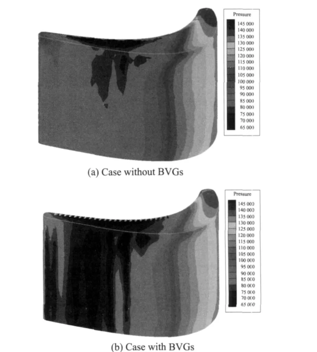
Fig.10 Pressure distributions of blade tip surface and suction surface
3.5 Influence of BVGs on mass of leakage flow and blade circumferential load
Table.1 is the variation of leakage flow mass and circumferential load with and without BVGs. The inlet Mach number is 0.293.Here,circumferential load represents the surface pressure and the viscous force in pitch direction.Because the viscous force is too small,the surface pressure plays a major role in the circumferential load. Compared to the case without BVGs,the mass of leakage flow decreases by 2.8% from 1.703 g/s to 1.655 g/s and the circumferential load increases by 7.7% from 1.744 N to 1.878 N by the affect of BVGs.Decrease of leakage flow and increase of circumferential load can increase the work ability and improve the turbine efficiency.
3.6 Influence of BVGs on turbine efficiency
The blade cascade used in this paper is a typical turbine rotor cascade. The flow efficient Cx/U of this cascade is 0.78 on design condition, where Cxis the axial velocity and U the rotational speed.The turbine efficiency is acquired by the numerical simulation results and the flow efficient.The efficiency is defined as

BVGs reduce the leakage flow and enhance the turbine works,so the turbine efficiency is improved clearly.The result shows that the turbine efficiency is 80.84% in the case of BVGs at inlet Mach number 0.293,and grows nearly 1.2% compared with that obtained under without BVGs condition.
4 CONCLUSIONS
A new technique for controlling tip leakage flow of micro turbine is presented by using backward vortex generators.The flow of BVGs jets backwards at high velocity from blade tip surface to block leakage flow.Numerical simulations of typical micro turbine cascade are performed with/ without BVGs at inlet Mach number of 0.293. The conclusions are as follows:
(1)The jet from BVGs interacts with leakage flow,thus forming an obvious low velocity area in half tip clearance near blade tip.The jet also makes the effective flow area of leakage flow smaller.The leakage flow is reduced because of the obvious low velocity area and the smaller effective flow area.
(2)Numerical simulations show that BVGs decreases mass of leakage flow and makes mainstream mass increase.The average Mach number increases and the pressure decreases in mainstream.So it makes circumferential load of blade increase.It is good for improving the work ability of turbine blade.
(3)Compared with the case without BVGs, the mass of tip clearance leakage flow is reduced by 2.8% and the circumferential load is enhanced by 7.7% in the case with BVGs at inlet Mach number 0.293.Besides,BVGs can improve the turbine efficiency.At the same inlet Mach number,the turbine efficiency grows almost 1.2%in case with BVGs,compared with that in the case without BVGs.
[1] Harris M M,Jones A C,Alexander E J.Miniature turbojet development at Hamilton Sundstrand the T J-50,TJ-120and T J-30Turbojets[R]. AIAA 2003-6568,2003.
[2] Bunker R S.Axial turbine blade tips:function,design,and durability[J].Journal of Propulsion and Power,2006,22(2):271-285.
[3] Lattime S B,Steinetz B M.Turbine engine clearance control systems:current practices and future directions[R].AIAA 2002-3790,2002.
[4] Rao N M,Camci C.Axial turbine tip desensitization by injection from a tip trench[R].ASME2004-GT-53256,2004.
[5] Van Ness D K,Corke T C,Morris S C.Turbine tip clearance flow control using plasma actuators[R]. AIAA2006-21,2006.
[6] Langston L S,Nice M L,Hooper R M.Three-dimensional flow within a turbine cascade passage[J]. ASME Journal of Engineering for Power,1977,99 (1):21-28.
[7] Langston L S.Crossflows in a turbine cascade passage[J].ASME Journal of Engineering for Power, 1980,102(4):866-874.
[8] Moore J,Adhye R Y.Secondary flows and losses downstream of a turbine cascade[J].ASM E Journal of Engineering for Gas Turbines and Power,1985, 107(4):961-968.
[9] Moore J,Tilton J S.Tip leakage flow in a linear turbine cascade[J].ASM E Journal of Turbomachinery,1988,110(1):18-26.
猜你喜欢
工会博览(2022年26期)2023-01-12
中国机械工程(2022年21期)2022-11-21
汽车实用技术(2022年7期)2022-04-20
中国机械工程(2022年7期)2022-04-20
数据采集与处理(2021年4期)2021-09-20
意林·作文素材(2021年12期)2021-08-09
航空发动机(2020年3期)2020-07-24
音乐教育与创作(2020年4期)2020-05-13
燃气涡轮试验与研究(2019年5期)2019-12-01
创新作文(小学版)(2019年21期)2019-01-11
 Transactions of Nanjing University of Aeronautics and Astronautics2011年1期
- Transactions of Nanjing University of Aeronautics and Astronautics的其它文章
- 空气系统引气对压气机性能影响的数值研究
- 由火焰聚心和激波聚焦诱导的爆震波研究
- 高温下IC10合金的动态再结晶特性研究
- 纤维失效对陶瓷基复合材料准静态加卸载迟滞回线的影响
- 正交铺设陶瓷基复合材料基体裂纹演化研究
- 内乘波式进气道与内型侧压式进气道性能分析